A Nonflammable Fluorinated Carbonate Electrolyte for Sodium-Ion Batteries
Guifang Zeng , Yining Liu , Chunyan Gu , Kai Zhang , Yongling An , Chuanliang Wei ,Jinkui Feng ,*, Jiangfeng Ni ,*
1 SDU & Rice Joint Center for Carbon Nanomaterials, Key Laboratory for Liquid Solid Structural, Evolution & Processing of Materials (Ministry of Education), School of Materials Science and Engineering, Shandong University, Jinan 250061, P. R. China.
2 School of Physical Science and Technology, Jiangsu Key Laboratory of Thin Films, Soochow University, Suzhou 215006, Jiangsu Province, P. R. China.
Abstract: Lithium-ion batteries (LIBs) are widely used in cellphones, laptops, and electric cars owing to their high energy density and long operational lifetime. However, their further deployment in large-scale energy storage systems is restricted by the uneven distribution of lithium resources (~0.0017% (mass fraction, w) in the Earth’s crust). Therefore, alternative energy storage systems composed of abundant elements are of urgent need. Recently, sodiumion batteries (SIBs) have attracted significant attention and are considered to be a potential alternative for next-generation batteries owing to abundant sodium resources (~2.64% (w) of the Earth’s crust), suitable potential (-2.71 V), and low cost. SIBs are similar to LIBs in terms of their physical and electrochemical properties. Previous studies have mainly focused on SIB storage materials, including hard carbon, alloys, and hexacyanoferrate, while the safety of SIBs remains largely unexplored. Similar to LIBs, the current electrolytes used in SIBs are mainly composed of flammable organic carbonate solvents (or ether solvents), sodium salts, and functional additives, which pose possible safety issues. Moreover, the chemical activity of sodium is much higher than that of lithium, leading to a higher risk of fire, thermal runaway, and explosion. To overcome this problem, herein we propose a fluorinated non-flammable electrolyte composed of 0.9 mol·L-1 NaPF6 (sodium hexafluorophosphate) in an intermixture of di-(2,2,2 trifluoroethyl) carbonate (TFEC) and fluoroethylene carbonate (FEC)in a 7 : 3 ratio by volume. Its physical and electrochemical properties were studied by ionic conductivity, direct ignition,cyclic voltammetry, and charge/discharge measurements, demonstrating excellent flame-retarding ability and outstanding compatibility with sodium electrodes. The electrochemical tests showed that the Prussian blue cathode retained a capacity of 84 mAh·g-1 over 50 cycles in the prepared electrolyte, in contrast to the rapid capacity degradation in a flammable conventional carbonate electrolyte (74 mAh·g-1 with 57% capacity retention after 50 cycles). To test the practical application of the proposed electrolyte, a hard carbon anode was used and exhibited exceptional performance in this system. The enhancement mechanism was further verified by Fourier transform infrared (FTIR), X-ray diffraction (XRD), and scanning emission microscopy (SEM) investigations. Polycarbonate on the surface of the cathode played an important role for the studied electrolyte system. The polycarbonate may originate from FEC decomposition, which can enhance the ionic conductivity of the solid electrolyte interface (SEI) layer and reduce impedance. Hence, we believe that this proposed electrolyte may provide new opportunities for the design of robust and safe SIBs for next-generation applications.
Key Words: Fluoroethylene carbonate; Non-flammable electrolyte; Sodium-ion battery; Di-2,2,2-trifluoroethyl carbonate
1 Introduction
SIBs, with abundant sodium resource (~2.64% (mass fraction)in earth’s crust), low cost and suitable redox potential (-2.71 V),have been considered as a prospective alternative to LIBs1–5.However, current electrolytes of SIBs are typically made up of sodium slats, flammable carbonate solvents (or ether solvents)and functional additives, which may bring about safety hazards2.Moreover, the chemical activity of sodium is higher than that of lithium, therefore, more safety issues may happen in SIBs6.Safety problems have been the key obstacle for its future development1,2,6–10.
To solve the above safety problems, using non-flammable electrolyte could be an effective way2,7. A large number of nonflammable solvents have been introduced into LIBs such as organic phosphates, fluorinated ether and non-flammable fluorinated carbonates and so on2. Among these non-flammable solvents, fluorinated carbonates are reported to possess the similar battery chemistry to conventional electrolyte, which can address the safety issues without sacrificing the battery electrochemical performance11,12. Besides, it has an outstanding ability to form an anode SEI film and tolerate higher oxidation13–15.Here, we proposed a non-flammable fluorinated electrolyte for SIBs, and to our knowledge, it is the first time using the nonflammable fluorinated carbonates for SIB.
Based on above considerations, we proposed a non-flammable electrolyte composed of 0.9 mol·L-1NaPF6(sodium hexafluorophosphate) in an intermixture of TFEC (di-(2,2,2-trifluoroethyl)carbonate) and FEC (fluoroethylene carbonate) (7 : 3 by volume). We found the electrochemical performance of Prussian blue cathode is improved with a stable reversible capacity in fluorinated electrolyte. Besides, the performance of hard carbon anode is also tested and shows a good result.
2 Experimental
All the chemicals were used as purchased. The control electrolyte composed of 1 mol·L-1NaClO4in an intermixture of EC (ethylene carbonate) and DEC (diethyl carbonate) (3 : 7 by weight) was obtained from Nanjing Mojiesi Energy Technology Co. Ltd. (China). Electrolyte was made by dissolving 0.9 mol·L-1NaPF6 in an intermixture (FEC : TFEC, 3 : 7 by volume), which was prepared in an Ar-filled glove box (H2O and O2content < 10-7). The cathode electrode was made up of Prussian blue, polyvinylidene fl uoride and carbon black (8 : 1 :1, by weight), the anode electrode was composed of hard carbon,sodium carboxymethyl cellulose and carbon black (8 : 1 : 1, by weight). Cyclic voltammetry (CV) using Pt working electrode was applied to measure the electrochemical properties, which were implemented on an electrochemical workstation (Shanghai,Chenhua). The XRD (a Rigaku Dmaxrc Diffractometer) and SEM (SU-70) were also used to characteristic the crystal structures and morphologies of the sample. FTIR pattern were prepared from a NICOLET AVATAR 360 FTIR spectrometer.
3 Results and discussion

Fig. 1 Molecular structure of solvents and salts used in this work.
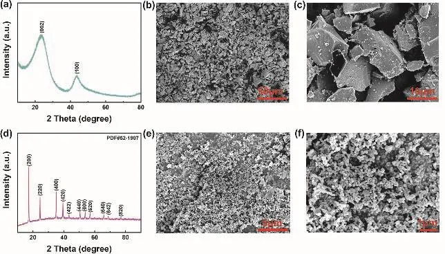
Fig. 1 displays the molecular structure of all solvents and sodium salts used in this work, containing TFEC, FEC, NaPF6,EC, DEC and NaClO4. The initial samples of Prussian blue and hard carbon were characterized by SEM and XRD (Fig. 2). As shown in Fig. 2a, two typical characteristic peaks of hard carbon at ~24° and ~43° appears, corresponding to crystallographic planes of (002) and (100)16. Fig. 2b, c show the morphology of hard carbon, which is in a fragment state with a size of ~10 μm.Fig. 2d illustrates the XRD pattern of Prussian blue, and Prussian blue is presented as nanoparticles with sizes of ~30 nm (Fig. 2f,e)7. Ionic conductivity of different molar NaPF6/FEC-TFEC electrolytes is also tested in Fig. 3a. From the pattern, we can see that the tendency of ionic conductivity firstly increases and then decrease. The ionic conductivity of 0.9 mol·L-1NaPF6/FECTFEC electrolyte is 1.13 mS·cm-1. The relatively low conductivity may be ascribed to the higher viscosity of fluorinated carbonates compared with carbonates17,18. A combustion test indicates the carbonates is very easy to burn,while the fluorinated electrolyte shows the excellent flame retarding ability (Fig. 3b, d). To explore the electrochemical window of electrolytes, CV measurements was applied from-0.5 to 5.5 V, as shown in Fig. 3c. There are a couple peaks between -0.5 and 0.5 V, which are obviously related to the reversible Na plating/stripping1,7. The oxidation peak of fluorinated electrolyte is at ~5.2 V. However, the oxidation potential of carbonate electrolyte is at ~4.5 V, indicating the fluorinated electrolyte possesses a wider electrochemical window1.

Fig. 2 (a) XRD pattern of hard carbon. (b), (c) SEM images of hard carbon. (d) XRD pattern of Prussian blue. (e), (f) SEM images of Prussian blue.

Fig. 3 (a) Ionic conductivity of NaPF6/FEC-TFEC at different concentrations. (c) CV plot of 0.9 mol·L-1 NaPF6/FEC-TFEC and 1 mol·L-1 NaClO4/EC-DEC electrolytes from -0.5 to 5.5 V at 5 mV.Flammability tests in (b) 1 mol·L-1 NaClO4/EC-DEC and(d) 0.9 mol·L-1 NaPF6/FEC-TFEC.

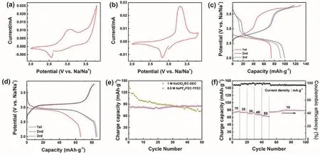
Fig. 4 The electrochemical performance of Prussian blue between 2 and 3.8 V. CV plots of the first cycle in (a) 1 mol·L-1 NaClO4/EC-DEC and(b) 0.9 mol·L-1 NaPF6/FEC-TFEC electrolytes at 0.05 mV s-1. The discharge-charge pattern in (c) 1 mol·L-1 NaClO4/EC-DEC and (d) 0.9 mol·L-1 NaPF6/FEC-TFEC electrolytes at 10 mA·g-1. (e) Cycling capability. (f) Rate performance in 0.9 mol·L-1 NaPF6/FEC-TFEC electrolyte.
To investigate the electrochemical performance of Prussian blue cathode in fluorinated electrolyte, galvanostatic charge/discharge measurements using 2032-type cells were implemented. Fig. 4a, b display CV plots of the first cycle of Prussian blue cathode in 1 mol·L-1NaClO4/EC-DEC and 0.9 mol·L-1NaPF6/FEC-TFEC from 2 to 3.8 V at 0.05 mV s-1. Two pairs of peaks at ~2.5/3.0 V and 3.5/3.8 V were appeared owing to the reversible phase transition of FeIII/FeIIand thefilled in the vacancies of Prussian blue in 1 mol·L-1NaClO4/EC-DEC electrolyte7,19. In 0.9 mol·L-1NaPF6/FEC-TFEC electrolyte,there is one pair of peaks ascribed to the reversible phase transition of FeIII/FeII(2.8/3.3 V). The 1st, 2nd and 3rd capacitypotential plots of Prussian blue in different electrolytes were presented in Fig. 4c, d. The initial discharge/charge capacity are 73/130 mAh·g-1and 61/71 mAh·g-1in 1 mol·L-1NaClO4/ECDEC and 0.9 mol·L-1NaPF6/FEC-TFEC electrolyte,respectively. The relatively low capacity in 0.9 mol·L-1NaPF6/FEC-TFEC electrolyte may be explained by the low ionic conductivity and poor wettability of fluorinated solvents17.However, after 50 cycles, it only remains a reversible capacity of 74 mAh·g-1with 57% capacity retention ratio in carbonate electrolyte. As a contrast, a capacity of 84 mAh·g-1was obtained in 0.9 mol·L-1NaPF6/FEC-TFEC electrolyte, indicating an outstanding cycling performance (Fig. 4e)2. Fig. 4f shows the rate performance of Prussian blue cathode in 0.9 mol·L-1NaPF6/FEC-TFEC electrolyte at rates of 10, 20, 30, 40, and 50 mA·g-1and the corresponding reversible capacities are 80, 76,72, 69, and 64 mAh·g-1. When it returns to 10 mA·g-1, 77 mAh·g-1was remained.
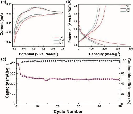
To test the practical application of 0.9 mol·L-1NaPF6/FECTFEC electrolyte, the performance of anode (hard carbon electrode) was also tested. Fig. 5a displays the CV pattern of hard carbon electrode from 0.01 to 2.5 V at 0.1 mV s-1. In the first cycle, a peak at ~0 V can be ascribed to the SEI formation20.Fig. 5b shows the 1st, 2nd and 3rd charge-discharge plots. The first discharge/charge capacities are 367/206 mAh·g-1. After 50 cycles, a capacity of 145 mAh·g-1remains, and the capacity decay can be attributed to the large particles size of the hard carbon (Figure 5c). All these results reveal the feasible application of fluorinated electrolyte for hard carbon anode20.

Fig. 5 Electrochemical performance of hard carbon in 0.9 mol·L-1 NaPF6/FEC-TFEC electrolyte from 0.001 to 2.5 V.
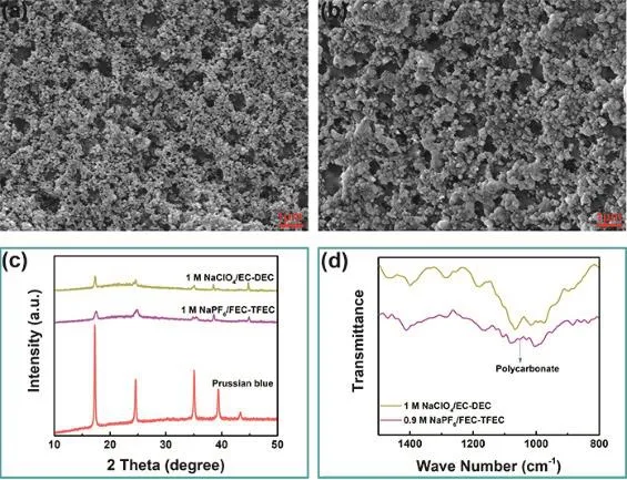
To investigate the mechanism of the excellent electrochemical performance of Prussian blue cathode in fluorinated electrolyte,SEM, XRD and FTIR measurements were carried out. Fig. 6a, b display the SEM images of Prussian blue electrode cycled in 0.9 mol·L-1NaPF6/FEC-TFEC and 1 mol·L-1NaClO4/EC-DEC electrolytes after 50 cycles. As we can see, a thicker film covers on the cathode surface in fluorinated carbonates electrolyte,which may be ascribed to the FEC decomposition21–23. Fig. 6c shows the XRD pattern of cathode in 0.9 mol·L-1NaPF6/FECTFEC and 1 mol·L-1NaClO4/EC-DEC electrolytes after 50 cycles. There is no obvious change in the crystal structure in carbonates or fluorinated carbonates electrolyte. Fig. 6d shows the FTIR pattern of the Prussian blue cathode cycled after 50 cycles. As we can see, the electrode surface in fluorinated carbonates electrolyte is rich in polycarbonate components24–26,which may come from the FEC decomposition. The presence of polycarbonate can enhance the ionic conductivity of SEI layer and reduce the impedance21–23.

Fig. 6 SEM image of Prussian blue electrode in (a) 0.9 mol·L-1 NaPF6/FEC-TFEC and (b) 1 mol·L-1 NaClO4/EC-DEC.(c) XRD pattern. (d) FTIR pattern.
4 Conclusions
In summary, we raised a new non-flammable fluorinated carbonate electrolyte for safe SIBs. The Prussian blue cathode exhibits an outstanding electrochemical performance in fluorinated electrolyte, and the improved performance is verified by EIS measurement. The electrochemical performance of hard carbon anode is also tested and shows a good result. This work may shed a prospective light on safe sodium-ion batteries.

