Theoretical and numerical investigations on the headspace of cartridge cases considering axial deformation and movement
Song Cai,Chen-lei Huang,Kun Liu,Zhong-xin Li,Zhi-lin Wu
School of Mechanical Engineering,Nanjing University of Science and Technology,Nanjing 210094,Jiangsu,China
Keywords:Cartridge case headspace Radial clearance Thick-walled cylinder Dynamic response
ABSTRACT The cartridge case headspace is the axial clearance between the cartridge and bolt of an automatic weapon,and influences the reliability and security of the weapon.Accordingly,theoretical and numerical studies were conducted to analyze the dynamic response of cartridge cases during internal impact considering the initial radial clearances between the cartridge case and chamber.A theoretical model was proposed to predict the cartridge case headspace considering both the deformation and movement of the cartridge case and confirmed by the results of nonlinear finite element simulations.The differences between the results of the conventional static model and the dynamic model were then comprehensively evaluated.The effects of the angle between the cartridge and chamber,the cartridge case material,and the internal impact pressure on the predicted headspace value were also analyzed.The dynamic response of the cartridge case predicted by the dynamic model was more accurate than that predicted by the conventional static model.The internal impact pressure,pressure change rate,and cartridge material were all found to affect the predicted headspace.©2020 China Ordnance Society.Production and hosting by Elsevier B.V.on behalf of KeAi Communications Co.This is an open access article under the CCBY-NC-ND license(http://creativecommons.org/licenses/by-nc-nd/4.0/).
1.Introduction
Clearances in machines are unavoidable due to manufacturing tolerances,assemblage,wear,and material deformation.In order to better describe the influence of clearances,many clearance analysis models[1-3]have been constructed.Meanwhile,the influence of clearance has been widely studied in various fields such as mechanical engineering[4-10],manufacturing[11],aerospace[12-15],and robotics[16-18].How ever,these studies only concern radial clearances,while axial clearances have been scarcely considered.Headspace is the axial clearance between the cartridge and the breech bolt,or between the bolt and the receiver.Inappropriate headspace may lead to failure to fire or rupture,possibly damaging the firearm and injuring the shooter[19].The headspace is also an important service life criterion of automatic weapons[20].
Over the last few decades,a significant number of researchers have studied the clearance effects on the dynamic response of weapons under blast loading.Xie and Yang[21]studied the influence of clearances on shooting accuracy,considering the radial clearance between trunnions and bearings.In Tasson and Sadowski[22],the axial clearance had a more significant influence on the maximum stress during internal impact than the radial clearance.Xu[23]and Dong[24]demonstrated the influence of headspace on the firearm bolt.Therefore,prediction of the maximum effective headspace of an automatic weapon is a significant consideration in engineering.Gordon[25]constructed a model to calculate the force and deformation of a cartridge in a chamber.Xuebing[19]and Wang[26]constructed a static analytical model that regards the axial deformation of a cartridge under the quasi-static condition as the maximum headspace.Shao-Min[27]and Cai[28]analyzed the maximum headspace of 12.7 mm cartridge cases with numerical simulations.These numerical analyses all indicated that the maximum headspace was greater than the cartridge deformation during f i ring.
Based on such previous research,this study attempts to predict the maximum headspace of cartridge cases using a theoretical approach.First,the deformation and movement of the cartridge during firing was calculated.A theoretical dynamic model was then constructed to characterize the maximum headspace of a gun and its results were confirmed by numerical simulations.The differences between the static model and the dynamic model under different material parameters,internal blast pressures,and structural parameters were then explored.
2.Theoretical dynamic model of head space
2.1.Fundamental assumptions
The deformation and movement of a cartridge in a gun chamber under the influence of propellant gas is quite complex.Due to the initial radial clearance between the cartridge and chamber,the contact state varies with the pressure inside the chamber.When t=0,the neck of the cartridge is just in contact with the chamber;at this time,the axial pressure on the cartridge is greater than the frictional resistance between the cartridge and the chamber,allowing the cartridge to move axially.As the pressure increases,the radial clearance is eliminated,leading to an increase in the contact area and pressure between the cartridge and the chamber,accordingly increasing the frictional resistance.Once this frictional resistance is greater than the axial pressure,the cartridge tends to behave statically,and after the cartridge has stopped moving,the resulting axial force causes the cartridge to axially deform.The axial deformation and displacement of the cartridge therefore both act to eliminate the headspace,resulting in complex dynamic cartridge behavior during the ballistic cycle.For ease of application and discussion of the equations,the following assumptions have been made in this study:
1)The cartridge is an axisymmetric,thick-walled cylinder,the shoulder and neck are neglected,and the chamber is an inner conical tube.
2)The deformation of the cartridge is considered during the rising pressure stage and the pressure is linearly related to time.
3)The cartridge and chamber are isotropic materials and their deformations remain within the elastic deformation range.
4)The influence of temperature is neglected.
2.2.Cartridge and chamber model
The model used for the calculations is shown in Fig.1,in which the inner diameter of the cartridge is 2a and its outer diameter is 2b;the outer diameter of the chamber is 2c;the angle between chamber and cartridge is β;the depth of the cartridge is l;the inside pressure of the cartridge is p;the elastic modulus and Poisson's ratio of the chamber are E1and ν1,respectively;the elastic modulus and Poisson's ratio of the cartridge are E2and ν2,respectively;the cartridge and chamber are isotropic materials;the sliding coefficient of friction between the cartridge and chamber is μ;and the maximum static coefficient of friction is identical to the sliding coefficient of friction.
2.2.1.Contact pressure between the cartridge and chamber
Once the cartridge is inserted into the chamber,there is an initial radial clearance δ between the two as follows:

As the ballistic cycle begins,the cartridge case expands to make contact with the inside of the chamber under pressure,after which the two simultaneously deform.Assuming that the cartridge and chamber are both thick-walled cylinders,according to Lame's equations[29]the following equation can be obtained to describe the displacement:

When the pressure inside the cartridge is p and the contact pressure between the cartridge and the chamber is pj,according to Eq.(1),the displacement of the outside wall of the cartridge ukand displacement of the inner wall of the chamber utcan be obtained as:
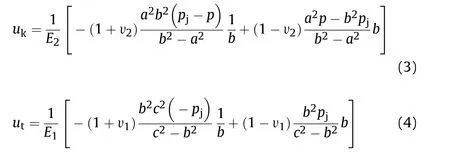
When the cartridge contacts the chamber,the deformation between the chamber and cartridge follow s the compatibility equation:

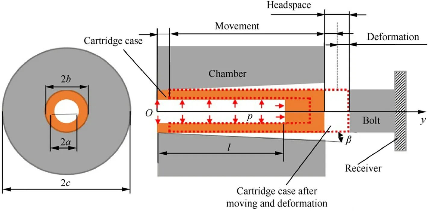
Fig.1.Cartridge and chamber model.
Combining Eq.(1)-Eq.(5),the contact pressure between the cartridge and chamber pjcan be obtained as follows:

When pj=0,according to Eq.(6),the real contact length lcbetween the cartridge and chamber can be obtained as:

When lc=l,according to Eq.(6),the pressure at this time,pl,is given by:

Therefore,the inside pressure p≥pl,so the cartridge is in complete contact with the chamber.
2.2.2.Axial elongation of cartridge
In a conventional model,the cartridge case experiences a static deformation under pressure.How ever,the contact length lcis not fixed equal to the depth of the cartridge,but rather varies as the pressure changes.The dynamic model must therefore calculate the axial deformation of the cartridge using the forces shown in Fig.2.In this model,the friction force on the cartridge case is not uniformly distributed,but rather consists of a static friction region located in the range[0,ls],where lsis the static friction length,and a sliding friction region located in the range[ls,lc].
The friction force on the microelement shown in Fig.2 is given by:

where Sc=2πb is the surface coefficient and μ is the sliding friction coefficient.
The strain on the microelement caused by the friction force is:

where Sj=π(b2-a2)is the cross-sectional area of the cartridge.
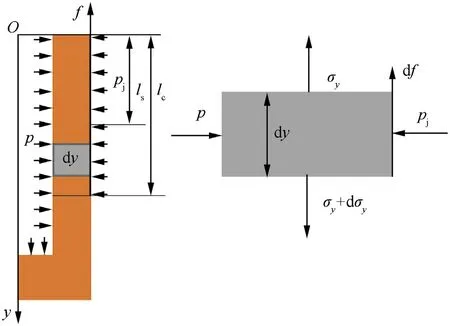
Fig.2.Force and stress on a cartridge microelement.
The axial elongation caused by the friction force is:

The friction on point y=lcfollows the function flc=p S,where S=πa2.Substituting Eq.(6)into Eq.(9),the friction on the cartridge case can be expressed as:

When β=0,only sliding region[ls,lc],expressed as the limiting length in the Automatic Weapons and Ammunition Infantry Design Handbook[20],will be influenced by sliding friction force and the static friction force flsis zero.Therefore,substituting fls=0 and tan β=0 into Eq.(12),the static friction length can be obtained as:

Combining Eq.(10),Eq.(11),Eq.(12),and Eq.(13),the axial elongation at point y=lccan be determined as:

where Δlsis the axial elongation at point y=ls.
When β=0 and fls=0,the forces in the static region[0,ls]can be simplified as a plane strain problem in elastic theory.According to Lame's Eq.(29),the axial strain caused by circumferential and radial deformation can be obtained by:

Substituting Eq.(15)into Eq.(11),the axial elongation of static region[0,ls]is determined as:

When β≠0,the friction is evenly distributed along the surface of static region[0,ls],andUsing Eq.(10)and Eq.(11),the strain and elongation at point y=lscan be written as:

Combining Eq.(12)and Eq.(13),the friction at point y=lscan be obtained by:

Combining Eq.(13),Eq.(18),and Eq.(19),the total axial deflection of the static region[0,ls]is:
Combining Eq.(14),Eq.(16),and Eq.(20),the axial deflection of the cartridge can be obtained as:
If pd>pmax,where pmaxis the maximum pressure on the inner cartridge case,the cartridge will continue to move,while if,the cartridge will stop moving.Becausev d t and,using Eq.(24)the equation for axial movement can be obtained as:

2.2.3.Axial movement of cartridge
When moving axially,according to Eq.(6)and Eq.(9),the sliding friction on the cartridge is given by:

With increasing pressure,the contact length between the cartridge and chamber increases.When the pressure is fairly low,the cartridge and chamber are not in complete contact with each other,that is,p≤l and the contact length is lc.Substituting Eq.(7)into Eq.(22),the friction can be obtained as:

Assuming that the inside pressure p=kt,where k is the rate of pressure increase and t is the time of movement,given an initial speed v|t=0=0,the axial speed of the cartridge is:

where M is the mass of all moving parts.
In order for the cartridge to stop moving,conditions must match p S<f.Once complete contact has occurred,the contact length of the cartridge does not increase again,but the cartridge is still moving,and the cartridge must continue to move.Therefore,the stationary condition of the cartridge is p≤pl,and given v=0 in Eq.(24),the stop conditions,expressed as the time tdand pressure pdof the cartridge,can be obtained as follows:


Substituting tdin Eq.(25)into Eq.(27)provides the total axial displacement of the cartridge:

This axial motion is described by an increment of the contact pressure Δpj=-CδΔmtan β,an increment of the friction Δf=-and an average increment of the accelerationtan β.Substituting these expressions into Eq.(27)provides the equation for the increment of axial motion as follow s:

and the axial displacement of the cartridge Δdcan then be modified to:

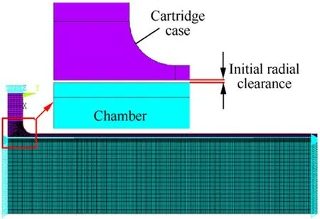
Fig.3.Finite element model of the cartridge and chamber.
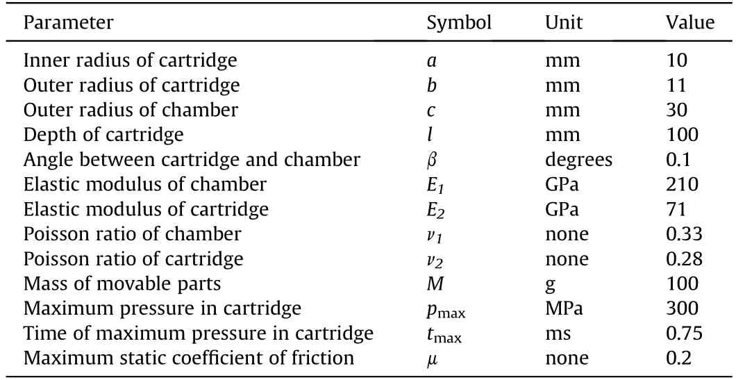
Table 1 Parameters of structure and materials of numerical simulation.
2.2.4.Dynamic headspace
In the dynamic headspace model,the axial clearance is eliminated through axial motion Δmand axial deformation Δs,so the maximum dynamic headspace is given by:

where Δsand Δmare calculated according to Eq.(21)and Eq.(30),respectively.
3.Numerical simulation
Both the deformation and motion of the cartridge occur within an extremely short period of time during f i ring.Furthermore,throughout the entire course of firing,the cartridge is located inside the chamber,making it difficult to observe and record its deformation and motion.Therefore,to verify the proposed theoretical model,a cartridge-chamber finite element model(FEM)based on a 12.7-mm machine gun,shown in Fig.3,was constructed in the ANSYS FEM software package using the parameters shown in Table 1.
The axisymmetric element“plane 183”was adopted to build the FEM,and the axial displacement of the chamber was constrained.The contact between the cartridge and the chamber was calculated using the penalty function method,the maximum pressure was 300 MPa,a transient analysis was conducted using a ramped-load method,and the calculation time was 0.75 ms.
4.Results and discussion
4.1.Error analysis between theoretical model and FEM
Using the parameters in Table 1,Eq.(31)was calculated using MATLAB,while the deformation and motion of the cartridge was modelled using the FEM.Taking the Y-direction displacement of the cartridge head as the maximum headspace in the dynamic model(Δd),and the Y-direction displacement of cartridge mouth as the axial movement(Δm),the subtraction ofΔmfrom Δdprovides the maximum headspace of the static model(Δs)of the cartridge,with the results shown in Table 2.
It is clear from the table that there is only a small difference between the FEM results and the theoretical values,amounting to less than 10%,indicating good agreement.When β=0 in Eq.(28),indicating that the initial radial clearance is zero,→0,thus Eq.(9)and Eq.(10)can be simplified into),which formally agrees with the expressionin conventional static theory[20],suggesting that the conventional static theory is a simplified model of the dynamic theory.The maximum headspace determined by the conventional static model is far smaller than that determined using the dynamic model,and with the increase in angle β,this difference gradually increases,indicating that axial motion is an important portion of the dynamic behavior of the cartridge in the chamber,and thus should not be ignored.
4.2.Parameter effects
Material parameters and pressure conditions have a remarkable influence on the design of lightweight cartridge cases[22].A onefactor analysis was used to study the effects of the different basic parameters defined for use in the experiments and shown in Table 1.The influence of these pressure and cartridge case material parameters on the dynamic model headspace(Δd),static model headspace due to only axial deformation(Δs),and dynamic axial motion(Δm)was evaluated by calculating the headspace while changing the single parameter in question.
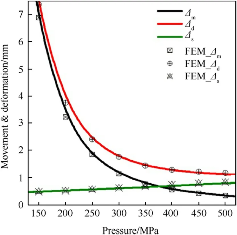
Fig.4.Influence of maximum pressure on headspace,in which the maximum pressure P max is changed while the other parameters are held constant at their values shown in Table 1.

Table 2 Errors between the results of theoretical model and FEM.
4.2.1.Influence of pressure
The headspace calculated using the dynamic model(Δdand FEM_Δd),as represented by Eq.(31),was always greater than that calculated using the static model(Δsand FEM_Δs),as shown in Fig.4 and Fig.5.As can be seen in Fig.4,with the increase in pressure,the dynamic solution gradually decreases because the dynamic axial motion(Δmand FEM_Δm),calculated by Eq.(30),tends to zero.When the pressure is low,the axial deformation of the cartridge is low,as is the friction,meaning that axial motion is the main component affecting the reduction of headspace.
In Fig.4,as the pressure increases from 150 MPa to 500 MPa,the headspace due to the axial deformation of the cartridge(Δsand FEM_Δs)increases gradually.From Eq.(21),note that a large axial deformation of cartridge increases the risk of transverse rupture of the cartridge.
As shown in Fig.5,keeping d p/d t=k constant,the movement of the cartridge is also constant.It can therefore be concluded that the movement of the cartridge(Δmand FEM_Δm)is related to the rate of pressure increase d p/d t.The expression Δm∝1/k2can be obtained from Eq.(28),indicating that as d p/d t increases,the dynamic axial movement of the cartridge(Δm)decreases.With the continued increase in pressure up to Pmax,d p/d t decreases,and thus the dynamic axial movement(Δm)of the cartridge also decreases in accordance with Eq.(28),as shown in Fig.5.
Fig.6 indicates that when the maximum pressure remains constant and as the time of maximum pressure(tmax)increases,the maximum dynamic headspace(Δdand FEM_Δd)of the cartridge increases with time.Though the static deformation of the cartridge Δsis small,the dynamic axial movement Δmof the cartridge is obvious.After 0.7 ms,the dynamic axial movement Δmof the cartridge is obviously greater than the static axial deformation Δsof the cartridge.
The increase in cartridge case static axial deformation(Δs)leads to an increase in the risk of cartridge rupture[20].In order to increase the ability of the cartridge to adapt to the chamber,the dynamic axial movement Δmshould be increased and Δsshould be decreased.Therefore,a decrease in pressure and an increase in its application rate should be adopted to enhance the safety of the cartridge in the chamber.
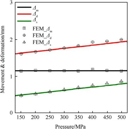
Fig.5.Influence of maximum pressure on headspace,determined by keeping d p/d t=k constant so that the maximum pressure P max changes with the time of maximum pressure t max.
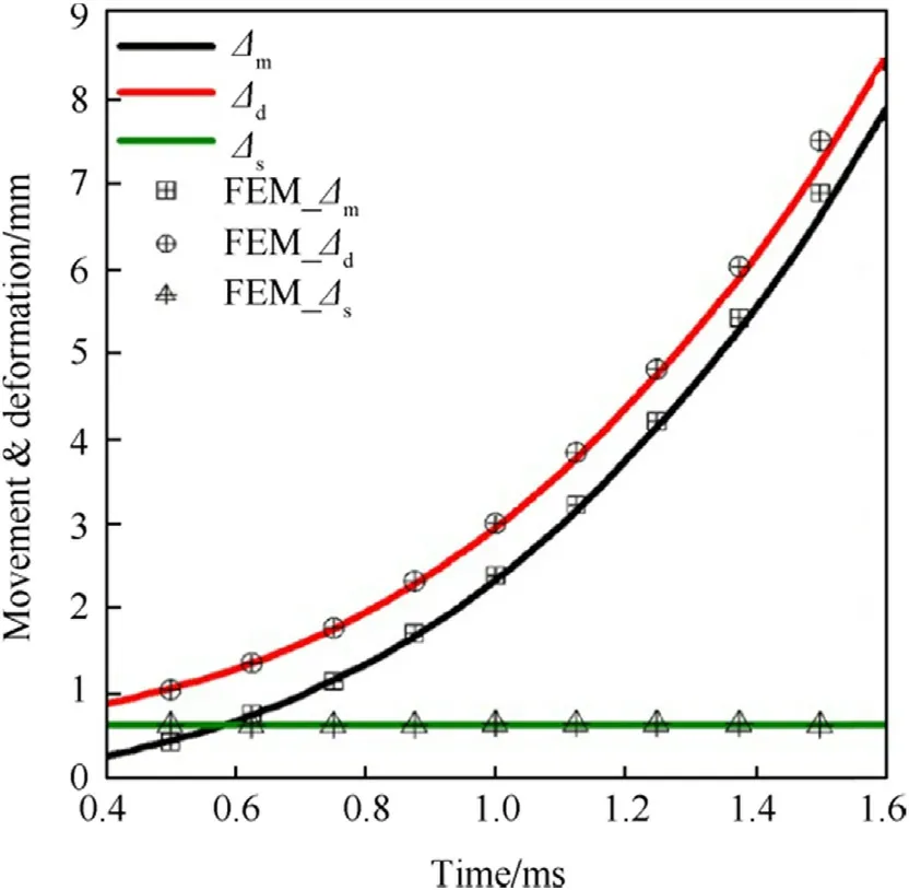
Fig.6.Influence of time of maximum pressure t max on headspace with other conditions held constant.
4.2.2.Influence of material properties
Currently,brass is widely accepted as the main material used to manufacture gun cartridges due to its excellent performance.How ever,with the continued development of military equipment,requirements for lightweight cartridges have been increasing[22].Different materials have very large differences in their elastic moduli,Poisson's ratios,and densities(Table 3).In this study,a magnesium(Mg)alloy cartridge with a mass of 15.6 g and an aluminum(Al)alloy cartridge with a mass of 24.3 g were selected for comparison with a brass cartridge with a mass of 73.7 g.The feasibility of these two materials in cartridge applications were accordingly evaluated against the performance of brass.
Due to the motion of the bolt,the headspace can be in any location between moving parts.When axial clearance is present between the cartridge and the bolt,the mass of the cartridge itself is considered,as shown in Fig.7.The maximum headspace(Δd)of the Al alloy cartridge corresponds to that of the brass cartridge,while the maximum headspace(Δd)of the Mg alloy cartridge is only a third that of the brass cartridge.Therefore,both the Al alloy and brass cartridges can guarantee safe use with maximum headspace.
It was assumed that the headspace was located between bolt and the cartridge case,but when evaluating the motion of the bolt,there may also be gaps between the bolt and the receiver.When headspace exists between the bolt and the receiver,the bolt will slide together with the cartridge case,thus the influence of the mass of the automatic bolt mechanism and its accessories on the model behavior must be considered.In this study,this mass was assumed to be 100 g.As shown in Fig.8,the maximum headspace(Δd)of the Al alloy cartridge is greater than that of the Mg alloy,butboth are approximately half that of the brass cartridge.No matter the location of the gap,the static axial deformation(Δs)of the Mg alloy is always larger than that of the other two materials.Because of the reduced headspace,the adaptability of the Al alloy cartridge and the Mg alloy cartridge to the surrounding environment is clearly inferior to that of the brass cartridge.

Table 3 Properties of different cartridge materials.
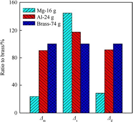
Fig.7.Influence of material on the movement and deformation of the cartridge in the chamber when the axial clearance is located between the cartridge and the bolt(including the mass of the cartridge).
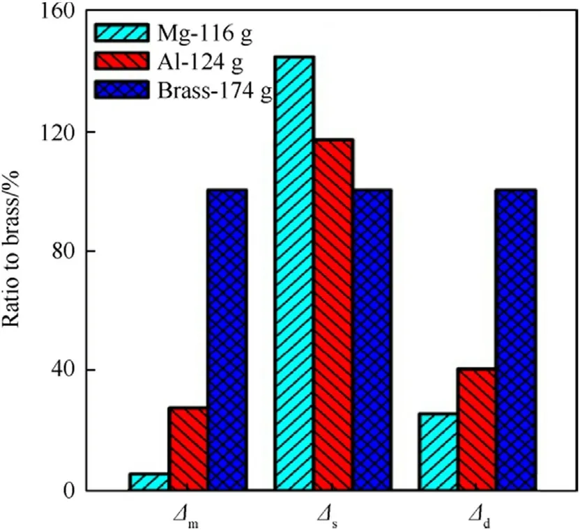
Fig.8.Influence of material on the movement and deformation of the cartridge in the chamber when the axial clearance is located between the bolt and receiver(including the mass of the bolt and cartridge).
As shown in Fig.9,when the mass of the Al alloy,Mg alloy,and brass cartridge/bolt are identical,the axial deformation(Δs)of the Mg cartridge is the largest under the dynamic model,and reaches the failure criterion of the cartridge case[20]at the same clearance as the other materials,indicating that transverse ruptures will tend to occur more readily in a Mg alloy cartridge.For the same mass,the headspace of the Al alloy cartridge is greater than that of the Mg alloy cartridge,but still less than that of the brass cartridge.Clearly,a high elastic modulus helps to increase the maximum headspace of the cartridge.
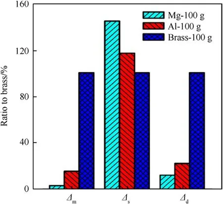
Fig.9.Influence of material on cartridge movement and deformation in static and dynamic models for a constant mass of different materials.
All in all,due to the poor headspace provided and the accompanying poor adaptability,the Mg alloy is not appropriate for use as a cartridge material.Under certain conditions,the environmental adaptability of the Al alloy cartridge corresponds well with that of the brass cartridge,but the comprehensive adaptability of the Al alloy cartridge is smaller than that of the brass cartridge.How ever,if a lightweight cartridge is required,the use of an Al alloy could be considered.
5.Conclusions
In this study,the deformation and motion of a cartridge in a gun chamber was theoretically and numerically modelled to determine the headspace under different pressure conditions and cartridge material parameters.The maximum chamber pressure pmax,the rate of pressure increase d p/d t,and the material properties were evaluated as variables,and the movement and deformation of the cartridge in the chamber were both theoretically analyzed and numerically simulated.The results of the theoretical analysis and numerical simulation indicate that:
(1)The simulation results are in agreement with the results of the theoretical calculation,and the motion of the cartridge along the chamber is revealed to be an important factor in determining headspace,thus should not be neglected in any analytical model.The conventional static theory is determined to be a simplified model of the developed dynamic theory.
(2)The axial deformation of the cartridge is directly proportional to the maximum chamber pressure pmax,while the axial movement of the cartridge Δdis inversely proportional to the rate of pressure increase d p/d t.Decreasing the chamber pressure and increasing the rate of pressure increase will help to improve the headspace and thus the behavior of the cartridge in the chamber.
(3)Materials with a high elastic modulus were found to enhance the headspace and thus the environmental adaptability of a cartridge.Specifically,Al alloys were found to be acceptable for use as lightweight alternative materials for cartridge cases.
The proposed dynamic model can thus provide a helpful theoretical reference when choosing the max cartridge headspace during weapon and bullet design.
Acknowledgements
The authors are very grateful for the reviewers' instructive suggestions and careful proofreading.This work was supported by the National Natural Science Foundation of China(Grant Nos.11372137 and 11602025)and Equipment Development Department of the Central Military Commission of China(Grant No.301030905).
- Defence Technology的其它文章
- An approach for predicting digital material consumption in electronic warfare
- Initial alignment of compass based on genetic algorithm-particle swarm optimization
- The non-isothermal gravimetric method for study the thermal decomposition kinetic of HNBB and HNS explosives
- A non-myopic scheduling method of radar sensors for maneuvering target tracking and radiation control
- Research on construction of operation architecture based on complex network
- Estimating the metal acceleration ability of high explosives

