
A review of dual-spin projectile stability
2020-04-09 18:34:32JmesNorrisAmerHmeedJohnEconomouSimonPrker
Defence Technology 2020年1期
Jmes Norris ,Amer Hmeed ,John Economou ,Simon Prker
a Centre for Defence Engineering,Cranfield University,Defence Academy of the United Kingdom,Shrivenham,SN6 8LA United Kingdom
b BAESystems,United Kingdom
Keywords:Guided projectiles Dual-spin Gyroscopic Dynamic Stability Canards
ABSTRACT This paper gives a succinct review of dual-spinprojectile stability and some technologies relating to them.It describes how the traditional stability factors from linear projectile theory are modified to better describe a controlled dual-spin projectile.Finally,it reviews works which have investigated how different aspects of a controlled dual-spin design can affect flight stability,primarily airframe structure and canard properties.A conclusion is given,highlighting important guidelines from the enclosed discussions.©2020 China Ordnance Society.Production and hosting by Elsevier B.V.on behalf of KeAi Communications Co.This is an open access article under the CC BY-NC-ND license(http://creativecommons.org/licenses/by-nc-nd/4.0/).
1.Introduction
Generic airframe stability has three distinct forms:static,dynamic and gyroscopic,quantified by the stability factors SS,Sd&Sgrespectively.At a specific instance,a projectile is‘stable’in one of these ways if the associated stability factor fulfils its respective inequality.If a body is statically stable then,under the influence of a small disturbing force,the body will act towards its original alignment.If a body is dynamically stable,the disturbance induces an oscillatory motion,which will damp until the body attains its initial alignment.Gyroscopic stability is the resistance of a rotating body to changing its axis of rotation.Stability factors are advantageous for projectile designers,as they allow a good estimate of ballistic stability without having to analyse a large flight envelope with numerical analysis,which can be time consuming and resource intensive.
Projectiles are spun to mitigate aerodynamic disturbances which may detrimentally affect the flight of the projectile.Guided projectiles are far more effective,albeit more expensive per unit,at achieving a desired effect on target;how ever they are primarily designed to be non-spinning.A Dual-spin projectile design is one possible solution to imparting the benefits of controlled flight onto spin-stabilised projectiles.This paper consolidates the major works to date,which describe the stability factors for single spin(un)guided and dual-spin(un)guided projectiles.Additional literature describing any aspect of dual-spin flight stability is enclosed and discussed.Any meaningful conclusions about projectile design which can be draw n from the enclosed analysis or discussions are listed.
Section 2 presents the origin and justification for the use of dual-spin projectiles,some useful technologies and novel guidance methods for generic guided projectiles.Section 3 provides a brief origin of the static,dynamic and gyroscopic stability factors from linear projectile theory,followed by a review of the major works to date which have built upon these factors to account for the addition of control surfaces,a dual-spin design and a combination of both.Section 4 gives a review of works which have investigated how stability can be analysed from other perspectives,as well as how it is affected by both projectile and control mechanism parameters.Section 5 gives a summary of the paper and important elements of the enclosed discussions.
2.Dual-spin projectiles and related technologies
This section explains why spin stabilisation is useful for projectiles along with some of the problems which can arise after implementing it.Guided projectiles are introduced along with the rationale behind the dual-spin configuration.Finally,relevant technology such as MEMS,piezoelectric actuators and novel methods of imparting a control moment are presented.
The projectile,as an effector,has been used in warfare for almost as long as warfare has existed.It has long been know n that spinning a projectile improves stability and since Greenhill's formula[1],that there is an optimal spin rate.Too little spin and the projectile will not have the gyroscopic inertia to resist the disturbing force experienced during flight and the precession will be too large.Too much spin and the gyroscopic inertia will resist the aligning aerodynamic forces from the aerodynamic design creating too large an angle of attack;know n as super-stability[2].Ballistic stability,as it is understood today,is defined as the ability of a projectile to maintain its trajectory,ensuring the desired range and designated level of accuracy is achieved.A ballistically unstable projectile will tumble during flight,adversely affecting the aerodynamics and thus the range and accuracy.Hence,spinning a projectile intends to alleviate the inconsistency and inaccuracy caused by these disturbances.
How ever,there are two notable instances of amplified instability when projectiles are spun.Spin-yaw resonance occurs when the spin rate approaches the yaw rate,the projectile may begin to undergo a large amplitude yawing motion called‘lunar’yawing[2].Catastrophic yaw occurs when a large yawing motion is amplified by non-linear Magnus effects,which creates further dynamic instability,leading to a cascade effect.Indeed,Magnus force interactions affect a projectile's flight in many ways,Seifert[3]has provided a comprehensive review of the Magnus effect and its implications in aeronautics.In another relevant study[4]CFD simulations were used to predict the aerodynamic coefficients and flow fields for a 25 mm spin-stabilised projectile.The goal being to deduce which parameters are necessary for an accurate computation of the Magnus moment and roll damping moment.While spun projectiles are subject to Magnus forces in flight,these can be reliably accounted for prior to projectile launch[5].
The accuracy demanded by today's weaponry has led to the development of guided weapons,where control and guidance hardware is incorporated directly into the projectile.Guided weapons provide substantial benefits over conventional ammunition,namely reduced collateral damage,improved lethality and effectiveness per unit.Conventional,non-spun,guided munitions are already well established in modern arsenals(e.g.M 982 Excalibur[6],M712 Copperhead[7]),primarily using control surfaces such as canards for control.How ever,the high RPM inherent with spin stabilisation is not conducive to the use of tracking sensors or guidance hardware.A relatively recent solution to this problem is to use a‘dual-spin’configuration,shown in Fig.1.The aft section of the projectile retains its high spin rate and innate gyroscopic stability while the foreword section,adorned with the guidance and control hardware,has a much lower spin rate.This design allow s spun projectiles to be controlled in instances where reducing the spin is detrimental or otherwise undesired,an example of this would be smaller calibres which are more susceptible to aerodynamic disturbances.If stockpiles of unguided,spin-stabilised munitions exist,they can be upgraded by replacing the existing fuse with a course-correcting fuse(CCF)which contains the control and guidance hardware[8].
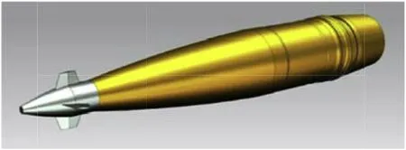
Fig.1.Depiction of dual-spin projectile(Liang et al.[57]).
Restricting the control and guidance hardware to such a small volume is driving the miniaturisation of sub-systems.As a result,technology is being adopted from other fields. Microelectromechanical Systems(MEMS)for example,are already being made more resilient due to use in aerospace[9].MEMS describe any system with moving parts on the micro-scale;relevant examples used in guided projectiles would be gyroscopes and accelerometers.Additionally,experiments are being conducted to adapt newer technologies,such as piezoelectric actuators,which are robust,have very high operational frequencies and no moving parts(aside from the physical deformation of the actuator).Different designs of piezoelectric actuators,such bi-morph actuators[10,11]and snap-through actuators[12],have been incorporated into projectile fins and control methodologies have been considered[13,14].Smaller designs usually equate to higher projectile speeds[15].It has been shown both numerically and experimentally,that conventional fin designs are able to produce significant deflections when subjected to supersonic speeds in excess of Mach 4[16](a 25 mm projectile achieved 1.4 m of deflection over a range of 160 m).
Much research has been conducted into unconventional control methodologies.While fins are still the primary source of control moments for projectiles,developments in these novel methods may prove useful in future guided weapon design,dual-spin or not.Project SCORPION,a collaboration between DARPA,U.S.Army Research Labs(USARL)and Georgia Institute of Technology,investigated the feasibility of mircoadaptive flow control(MAFC)as a means to control spin stabilised projectiles[17].It utilised the Coanda effect interaction with the projectile boattail,in combination with a high frequency piezoelectric actuator which distorts the boattail.The USARL have also proposed and analysed an asymmetric,spin stabilised projectile controlled by a singular fin or‘paddle’[18].‘Tail-spoilers’have been proven able to manoeuvre a 105 mm projectile at speeds up to Mach 3[19],with a range enhancement of 7%or a controllable deflection of 1.5 km,over a 10 km range.Tests have been conducted with an articulable nose/ogive,achieving bandwidths of up to 200 Hz at Mach 3.3[15].Microvanes have been investigated as a method for flow control on a supersonic spinning projectile[20].It was found that the vanes inhibit flow separation on the surface of the projectile,the normal force coefficient and pitching moment stabilised,which led to greater projectile stability via reduced oscillations.In addition,there exist a plethora of patents[21-25]describing novel guidance methods such as air jets,gyroscopes and asymmetric ogives.Since fin control methods are so predominant,they are assumed to be the source of all control moments throughout this paper.
3.Stability factors
Many popular textbooks and literature[2,26-30]can provide a detailed derivation of the stability factors from linear projectile theory,this section gives a brief description following McCoy[26].It then elaborates on the relation between these factors and their importance in determining the effect projectile dimensions have on ballistic stability.Then it is shown how different works to date have modified these factors to account for different iterations of projectile models.The DOF models form which the stability factors are derived from have been shown able to replicate technical data and atmospheric flight models,when applied to small calibre munitions[31].The NATO Armaments Ballistic Kernel(NABK)also utilises a 6-DOF model,which has also been shown to predict the behaviour of small calibre munitions(7.62 mm×51 mm)[32].Additionally,the statistical methodology used to evaluate projectile dispersion during that study characteristics is sufficient[33].
3.1.Classical aeroballistic stability factors
The static stability factor Ss,for a projectile of mass m,is given by

where CM αis the overturning moment coefficient as a function of angle of attack α,or CMα≡∂CM/∂α[34].A body has‘positive’static stability(i.e.is statically stable)if SS<0;SS=0 and SS>0 correlate to neutral and negative static stability respectively.Depending on whether the static stability is positive,neutral or negative,the body's alignment after a disturbance will respectively:return to its original position,maintain its new alignment or continue moving in the direction of the disturbance.Apart from CMα,all parameters in Eq.(1)are positive,hence to achieve SS<0 we necessitate that CMα<0;for a non-spin stabilised body this means practically that the COM is located ahead of the centre of pressure(COP).Fig.2 shows a plot of the relation between CMandα,static stability is present when the line pertaining to a given body has negative gradient.To optimise SSbased on the coefficients of CMα,a heavy projectile with a large cross section and small transverse moment of inertia is preferable,though this contradicts conventional ballistic design.
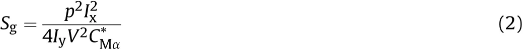
The procedure for deriving the gyroscopic and dynamic stability factors involves solving,under a series of assumptions,the equations of motion(EOM)for a projectile model and imparting boundary conditions on the solutions.In the most basic case presented,we assume a spin stabilised,uncontrolled projectile which is aerodynamically symmetric,has a rigid body,a uniform density and the centre of mass(COM)located on the longitudinal axis.Euler angles and angles of attack are assumed to be small and the effects of gravity are neglected.The solutions to a projectile's EOM describe damped oscillatory motion with two modes;a large amplitude slow frequency‘precession’(ωp)and a low amplitude fast frequency‘nutation’(ωn)with damping frequencies λpand λnrespectively.For the solutions to represent real and damped oscillations,we impose boundaries on the oscillation and damping rates.From the resulting inequalities,the gyroscopic stability factor is defined as
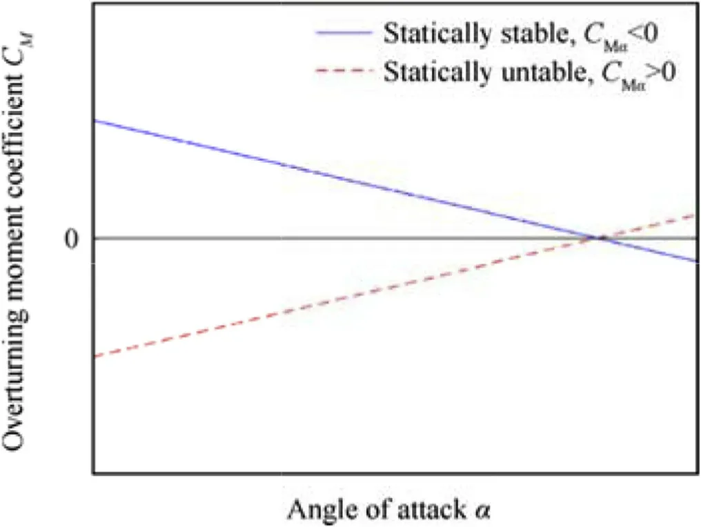
Fig.2.Example of overturning moment coefficient C Mαagainst angle of attack α for two abstract bodies.
The dynamic stability factor is defined as

N.B.the last two terms in the denominator of Eq.(3)are only included by some texts[26,29]to account for variable velocity due to drag and gravity.These equations are cumbersome so they are written in a more compact notation using substitution parameters,the gyroscopic stability factor is written as

and the dynamic stability factor is represented as

Future iterations of the stability factors are written in this compact form and all substitution parameters are shown in Appendix A.The mathematical condition for gyroscopic stability is Sg≥1,though it has been shown that the ballistic coefficient of a bullet is adversely affected by tumbling as Sgis lowered past a threshold of 1.3[35].The ratio p/V decreases along the trajectory of an uncontrolled projectile(assuming flat-fire),thus it is apparent Sgwill decrease down range.A projectile is dynamically stable if

By substituting Sgfrom Eq.(4)into Eq.(6)we can define the axial spin limit Slimfrom the resulting inequality,

which shows the critical value of P2for which the inequality in Eq.(6)is no longer satisfied.Fig.3 shows a plot of the corresponding equality of Eq.(6),with the shaded region indicating where the inequality is fulfilled.
Dynamic stability is concerned with the oscillations induced in a moving body after a disturbance is applied and as with static stability,it can be positive,neutral or negative.With positive dynamic stability the oscillations eventually damp towards the original alignment,neutral dynamic stability causes oscillations to reside indefinitely with constant amplitude,while negative dynamic stability has oscillations which amplify chaotically.When Sd=1 the body has positive dynamic stability,or is perfectly dynamically stable.If Sd<1 the precession is unstable and if Sd>1 the nutation is unstable,both catastrophically so at the asymptotes(Sd=0 or Sd=2 respectively).The transition from positive to neutral to negative dynamic stability for a projectile is dependent on the magnitude of the deviation from Sd=1.The magnitude at which the transitions occur is dependent on the projectile and trajectory parameters,but is not well characterised.Provided 0<Sd<2 in practice,the projectile can be spun sufficiently to ensure ballistic stability.Table 1 shows the effect on ballistic stability of occupying different static and dynamic regimes.
Note that the projectile geometry required to maximise aerodynamic efficiency and terminal effectiveness,almost always results in negative static stability.From Table 1 we can see that in the unstable static regime,a dynamically stable projectile can still be ballistically stabilised if the spin rate is sufficiently high.Thus,projectile designers can effectively disregard the static stability of a projectile,solely focusing on the relation between Sdand Sg;i.e.it is sufficient,to ensure a prototype projectile lies in the stable region(as central as possible)of Fig.3 for the anticipated flight envelope.
Fig.4.Dynamic stability plot of various NATO calibres for different projectile velocities.
Fig.4 shows a dynamic stability plot for three conventional NATO calibres: 5.56 mm×45 mm, 7.62 mm×51 mm and 12.7 mm×99 mm.The bullet geometry is loaded into PRODAS ballistic software and calculated for flat-fire trajectories.Each line represents one calibre,each point on the line represents a pair of stability factors calculated at a given bullet velocity.The velocity range is Mach 1.5-4 in increments of 0.5,the low est speed corresponds to the lowest/left most point of each line,increasing progressively.
3.2.Stability factor development
To account for the contribution of passivated control surfaces(canards or fins),a term n can be appended to the EOM[30,36],where

Note that the n term could be modified to account for any of the novel control methodologies described at the end of Section 2,provided the control moment can be characterised and integrated into the EOM.If the same mathematical treatment as above is applied to this modified EOM,the result is that Sdis unaffected,while Sgbecomes:
At least for the assumptions of this model,the canard parameters considered only affect Sg,not Sd.In a comprehensive paper by Costello et al.(2000)[37]a dynamic model was produced for a dual-spin projectile with no control surfaces,which utilised a 7-DOF model.The stability factors derived from this are shown below in Eq.(11)and Eq.(12).
Burchett et al.[38]developed this model further to analyse the effect that lateral pulse jets,as a method of control,have on the swerving motion of a projectile;though they did not derive any stability factors for their model.Costello uses the same assumptions as the classical case with the addition that V,φA&φFare large compared to the dynamic model coordinates θ,ψ,q,r,v,&w,so a product of any of these small quantities and any of their derivatives is negligible.
Wernert(2009)[39]expanded this dual-spin model to include the contribution of passivated canards,leading to the following stability factors
Comparing Eq.(11)and Eq.(13),we can see the method for including canard effects for the dual-spin design is analogous to the single-spin design between Eq.(4)and Eq.(9),the addition of a term in the denominator.How ever,Wernert remarks that the Sdhe arrived at is not satisfactory since the contribution of the canards to the Magnus forces/moments was not considered.
Zhu et al.[40]further developed this model by including terms to account for the effects of gravity and Euler pitch angle(θE),which led them to the following stability factors.
Using the assumption of a flat fire trajectory,θE=0,the stability factors were then shown to reduce and remain consistent with the previously established theory.Fig.5 illustrates the model and various parameters used by both Wernert and Zhu et al.The value of Sgin Eq.(4)for a single spin,uncontrolled projectile has been validated for conventional small scale projectiles[35],though the dual-spin modifications to Sgmade by Costello,Wernert and Zhu et al.are yet to be validated for small scale,due to the absence of such small scale dual-spin prototypes.
Fig.6 shows a comparison of each iteration of the stability factors,equations(4),(5),(9)-(14),for a 155 mm projectile.There is an inherent difficulty in directly comparing these equations,since they model fundamentally different projectiles.We can assume the total mass of a single spin projectile is the sum of masses of the forward and aft sections.Canards are assumed to have negligible mass,yet still provide an aerodynamic moment.The aft spin rate is chosen to be equal to the single-spin(1445 rad/s)while the forward section is chosen be sufficiently low to allow the operation of control and sensing hardware(30 rad/s).The aerodynamic coefficients,moments of inertia and balancing distances(R(A,F)x,Rm(A,F)xr(A,F)x)were calculated using a projectile model in PRODAS,once the single spin projectile was divided into two distinct sections.It is worthwhile to note which modifications to a dual-spin projectile are necessary to achieve the stability of a single-spin projectile.However,this optimisation task is very complex and beyond the scope of this paper,since all aerodynamic coefficients are functions of projectile geometry.
4.Works pertaining to dual-spin stability
This section review s publications which consider different elements affecting projectile stability from a perspective other than stability factors.The chapters categorise a number of publications which have a similar focal point.
An alternative method of stability analysis,conducted by Theodoulis et al.[41],created a linear-parameter-varying(LPV)model for a canard guided,single spin projectile.The aerodynamic information is encoded into certain state space matrices,the eigenvalues of which correspond to the precession and nutation frequencies of the projectile at any given instance.Additionally,root locus analysis of the system can identify stable operating regions,the parameters of which can be obtained and substituted into the stability criteria,depending on how the system is modelled.Indeed,ISL have conducted a significant amount of research into the modelling and control of dual-spin projectiles[39,41-45].
The‘Miller twist rule’is an imperial unit formula which can be used to calculate the optimal twist rate of a barrel as a function of bullet attributes and Sg[5],thus it can also be used to determine Sgif the twist rate is know n.Courtney et al.has shown empirically,that the Miller rule can be modified for use with plastic tipped bullets with non-homogenous densities[46],as well as for open tip style bullets[47].
Fig.5.Depiction of dual-spin projectile model(modified from Ref.[40]).

Fig.6.Dynamic stability comparison for each iteration of stability formula.
4.1.Airframe
Lahti et al.[48]designed a methodology to control the exterior ballistic properties of a spinning projectile by re-distributing the centre of mass around the inside of the bullet.The stability factors used in the paper follow McCoy[26],an appropriate usage since bullets are single-spin stabilised projectiles with no control method.The aerodynamic coefficients used in the analysis are calculated from a modified version of Slender Body Theory[49],where a correction termis appended to account for f l ow compressibility.While it is stated the coefficients are not well estimated near the transonic boundary,they are assumed to be representative based on experimental data[50].A bullet model was created with a large number of cells populating the interior,each may possess a specific density.A global optimisation algorithm was then used to find the mass distribution which can provide ballistic stability at the lowest velocity,by satisfying the stability factors.Since velocity decreases with projectile range,this method will find the mass distribution which enables the longest range(a training round with limited range was also investigated,but this review is mainly concerned with results from the long range specimen).Fig.7 shows the result from their paper.
It is stated the Magnus effect is the main method by which the mass distribution affects stability,especially toward the aft of the projectile[26].From Fig.7,it is apparent the algorithm selected the largest available density to populate mostly the aft of the projectile,which has the effect of minimising the resulting Magnus moment.These results indicate that mounting control and guidance hardware in the forward section of a projectile is beneficial for projectile stability,since electronic components generally have a lower density than the conventional core material,lead.
Jintao et al.[51]have investigated the effects to flight stability and manoeuvrability caused by the elastic deformation of a spinning projectile by conducting numerical simulations.It was shown that aerodynamic coefficients increase with movement frequency,that an elastic deformation induces two aerodynamic components opposite and perpendicular to the deformation,and that the induced angle of attack from deformation decreases as Mach number increases.
Xu et al.[52]have modelled the stability factors for a missile under thrust,assuming a flexible chassis.It was shown that thrust has a‘critical value’where dynamic stability is maximised;if thrust ishigher or lower than the critical value,then dynamic instability is induced by elastic or rigid vibrational frequencies respectively.Additionally,structural stiffness is low ered as thrust increases,which leads to reduced static stability.
4.2.Canard modification and general control
Chang et al.[53]have investigated the spin-rate of dual-spin projectiles as a function of canard properties,by characterising the ratio of aft to forward axial moment of inertia,IAx/IFx.The canards were modelled with zero deflection angle,so any contribution comes purely from the roll damping moment.It was found that for an initial spin rate of 420 rev/s(muzzle velocity 980 m/s with elevation angle of 45°),the dual-spin configuration itself causes a spin-rate discrepancy of 25 rev/s between the aft and forward sections,while deploying the canards led to a difference of 250 rev/s.The spin attenuation of the aft section was greater for values of IAx/IFx<1,while the spin attenuation of the forward section was greater for values of>1.For very large values of IAx/IFx,the aft section spin-rate was found to drastically reduce at first,then increase for a short period and finally attenuate as prior.Impact point drift was caused by any deviation from IAx/IFx=1.The maximum angle of attack was found to increase drastically to 16°for IAx/IFx<0.3,but remain around 1.7°for all IAx/IFx>0.3.The ratio of inertial moments has significant effects on both spin rate and angle of attack and must therefore be considered carefully during the design of a dual-spin projectile.
Fig.7.The optimal mass distribution of a long range bullet,Lahti et al.[48].
Wang et al.[54]have conducted numerical simulations investigating the effect of yawing force frequency on the angular motion and ballistic characteristics of dual-spin projectiles.The precession and nutation rates(λpand λn)were calculated following the linear theory described in Ref.[26].It was found λpand λnfor the system decrease over the projectile trajectory.As a result,the spin-rate of the aft or forward section could coincide with these intrinsic frequencies at certain intervals,which are dependent on the chosen projectile parameters.At resonance,there is an increase in angle of attack(~0.2°)and decrease in projectile range(~0.4 km decrease over~33.5 km).A Monte Carlo simulation was then conducted,which showed a 10 Hz control force applied to the projectile reduces projectile dispersion,but not significantly.
Cooper et al.have investigated the implications on flight stability caused by projectile asymmetry from the addition of canards[55].Linear projectile theory was extended to account for radial mass asymmetries,which was shown to reduce back to standard theory when the asymmetry was zero.The dynamic stability of the projectile was found by root locus analysis of the system eigenvalues in state space,in the same way as Theodoulis et al.[41,42,44].The canards were modelled with sinusoidal actuation,when the frequency of this driving wave is close to λpor λn,dynamic instability results;this is in agreement with the investigation of[54].When the actuation moment of the canards was sufficiently large,it was shown to adversely affect the oscillatory motion of the projectile,leading to ballistic instability.
Chang[56]has studied the dynamic response of a dual-spin,canard-stabilised projectile,when the coupling between canard control and gravity are considered.A new analytical solution was proposed to predict the maximum angle of attack induced by canard actuation,the yaw of repose due to canard control and the phase shift of the swerve response.It was found if the moment imparted on the projectile by the canards,or‘control moment’,is large then it will more drastically alter the trajectory,but lead to airframe instability.
Wang et al.[36]investigated the effects of different control strategies on the flight stability criterion derived in Ref.[40],by assuming all parameters other than those associated with the rolling motion of the body to be invariant.It was found that canards should be designed so the produced roll moment is as small as possible.During the period in which the roll angle is adjusted,it was found that control strategy has no impact on flight stability;it was suggested that the target spin rate of the forward section should be as low as possible for practical purposes(as discussed in Section 1).The behaviour of the motor torque was also characterised in terms of both trajectory and projectile parameters.
Liang et al.[57]have proposed a methodology for optimising the aerodynamic parameters of control canards.A 3D model is created with chosen canard parameters,then the aerodynamic coefficients for this are generated through the CFD program FLUENT and the efficiency is analysed by mapping how the normal force coefficient(CNα)changes with respect to canard deflection angle,over different angles of attack and Mach numbers.It would be interesting to see how this methodology could improve if used in conjunction with all the works listed above,where the canards’performance is quantified for each mechanism of affecting projectile stability,for varying control strategies,and having the optimum configuration selected based upon this.
5.Conclusions
This paper has shown the origin of stability factors,their use and interpretation for projectile design and how they should be modified to describe a dual-spin,controlled projectile.When more dual-spin prototypes are available,further work should involve validating the 7-DOF models used in numerical analysis.What follows is a summary of the publications reviewed here,aiming to provide guidelines to maximise the ballistic stability of a prototype projectile;full detail being found in the accompanying reference.
Lahtiet al.[48]have shown that mass should be concentrated at the back of the projectile as much as possible,to increase the range.Jintao et al.[51]have shown that an increasing airframe vibrational frequency,or increasing elastic deformation amplitude,will increase aerodynamic coefficients through an increasing angle of attack,at a rate proportional to Mach number.Xu et al.[52]showed that projectile thrust has an optimal value to maximise dynamic stability,which is dependent on airframe parameters.This is not so applicable to gun-launched projectiles but is an important consideration nonetheless.Chang et al.[53]show ed that spin attenuation of the aft/forward section increased for IAx/IFx<1 and IAx/IFx>1 respectively,and that maximum angle of attack increases drastically(~16°)for all IAx/IFx<0.3,remaining almost constant(~1.7°)otherwise.The intrinsic nutation and precession frequency,which are dependent on airframe parameters,decrease over a trajectory.It has been sow n that the control force frequency(Wang et al.[54])and canard actuation frequency(Cooper et al.[55])should be chosen to avoid these modes if possible.Chang[56]has shown that if the control moment of the canards is too large then ballistic stability is affected.Finally,Wang et al.[36]have shown that the roll moment of the canards should be as small as possible.
Conflicts of interest
None to declare.
Funding
This paper was sponsored by EPSRC ICASE Grant reference 1700064 and BAE Systems.
APPENDIX
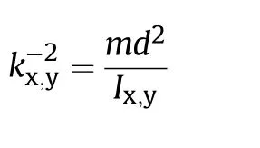
A.Substitution parameters Single-spin no canards(Classic)
The last two terms of H are added by certain authors[26,29]to represent variable velocity due to gravity and drag.
where
Canard Guided
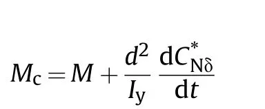
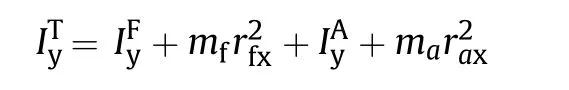
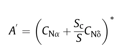
Dual-spin without canards
Any symbol with an A or F subscript or superscript indicates the usual meaning of the symbol,but with respect to the Aft or forward section of the projectile respectively.
where
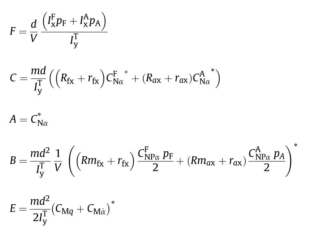
Dual-spin with canards
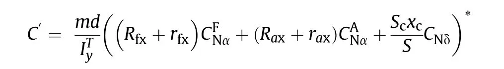
Then by Zhu
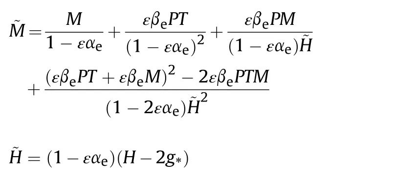
Where g*=gl sin(θT)/V2and ε=0.5 tan(θE).
- Defence Technology的其它文章
- An approach for predicting digital material consumption in electronic warfare
- Initial alignment of compass based on genetic algorithm-particle swarm optimization
- The non-isothermal gravimetric method for study the thermal decomposition kinetic of HNBB and HNS explosives
- A non-myopic scheduling method of radar sensors for maneuvering target tracking and radiation control
- Research on construction of operation architecture based on complex network
- Estimating the metal acceleration ability of high explosives