Simulation of Ship Motions Based on the HOBEM Acceleration Potential Method
LI Zhi-fu , REN Hui-long , SHI Yu-yun
(1. School of Naval Architecture and Ocean Engineering, Jiangsu University of Science and Technology, Zhenjiang 212003,China; 2. College of Shipbuilding Engineering, Harbin Engineering University, Harbin 150001, China)
Abstract: A 3D time domain method based on acceleration potential and higher-order description of ship hull has been developed to predict wave induced ship motions and loads. Both the velocity potential and acceleration potential are solved by boundary integral equations, with the transient free surface Green function as integral kernel. The eight nodes higher-order panels are used to discrete the integral equations, and the corresponding shape functions are applied to compute the spatial partial derivatives of the velocity potentials. Good agreement with the published experimental measurements demonstrates that the present method is reliable in a number of applications.
Key words: ship motion; acceleration potential; higher-order panel; Green function
0 Introduction
Accurate prediction of ship motions and wave loads is important for ship design and operation. Extreme loads can cause the structure failure, while large motions can influence the comfort and limit the operability. It is known that the strip theory was developed earlier and has been modified for the prediction of ship hydrodynamics[1]. However, to take into the 3D effects,which is important for the prediction of local pressures, the development of advanced 3D methods is expected by both engineers and scholars. Compared with the frequency domain analysis,the time domain method is more preferable for its ability in the nonlinear analysis.
So far, the 3D time domain methods developed for seakeeping analyses can be categorized into two major groups: the Rankine source panel method and the free surface Green function panel method.
The merit of the Rankine panel method is its flexibility in the treatment of the complicated free-surface conditions. However, for the Rankine panel method, the free surface surrounding the body has to be discrete, which will increase the unknowns and also introduces the numerical dispersion, dissipation, and instability[2]. Nowadays, some computer codes based on this theory have been developed for the seakeeping problems. The code called ship wave analysis (SWAN) has been developed for the linear and nonlinear seakeeping problems by the efforts of Nakos[3], Kring[4]and Huang[5]. Recently, Kim[6]develop a similar computer codes,named wave-induced loads and ship motion (WISH) and extended it to the spring and whipping problem analysis[7].
The time domain free surface Green function itself satisfies the radiation condition, linearized free surface condition and the bottom boundary condition. Therefore, only the wetted body surface needs to be integrated if this Green function is adopted as the integral kernel.Lin and Yue[8]applied this Green function successfully to the linear and nonlinear 3D forward speed ship motion simulations. Singh[9]did the comparison studies of the linear and nonlinear solutions systematically, using the B-spline description of the ship hull. Recently, Datta[10]applied this method to the motion simulation of the fish vessels, and to avoid the divergence problems, the panels adjacent to the free surface have been modified. One of the disadvantages of this method is that for the body-nonlinear analysis, the scheme is time-consuming in longterm simulations due to the time convolution integral nature. Therefore, the higher-order descriptions of the ship hull are preferred to accelerate the geometry convergence speed, e.g. the work of Chuang[11].
In the body nonlinear analysis, the finite difference scheme is usually adopted to compute the Euler time derivatives of the velocity potentials. In order to reach the desired accuracy, the small time intervals are usually required. Besides, the finite difference scheme can not give a reasonable result for the condition that the number of panels changes between time steps. To overcome these difficulties, the acceleration potential is introduced to compute the Euler derivatives directly from the boundary integral equation[12].
The aim of this paper is to develop a robust numerical tool for the motion and wave load simulations of 3D surface piercing bodies. The disturbed velocity potentials are solved by the mixed source boundary integral equation (BIE) with the transient free surface Green function as the integral kernel. The eight nodes higher-order panels are used to discrete the BIE, and the corresponding shape functions are applied to compute the spatial partial derivatives of the velocity potentials. Besides, the acceleration potential is introduced and the related boundary conditions are derived, and then solved by the same BIE as that of the velocity potential.
1 Mathematical formulation
1.1 Initial boundary value problem
To describe the fluid flows and body motions, two right-handed Cartesian coordinate systems are defined. One is the space-fixed coordinate system Oxyz, whose (x, y) plane coincides with the mean free surface and z-axis positive upwards. The other is the body-fixed coordinate system Obxbybzbwith its origin placed at the center of the mass of the body. At initial time,these two sets of coordinate systems are parallel to each other. The mean forward speed U of the ship is assumed to be along the positive x direction.
The fluid is assumed to be incompressible and inviscid, and the flow to be irrotational. As a result,the fluid flow can be described in terms of the velocity potential. To be convenient, the total velocity potential φTis decomposed into the known incident wave velocity potential φIand an unknown disturbed velocity potential φ as follows:
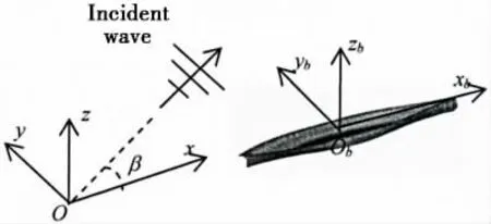
Fig.1 Definition of the coordinate system

In the fluid domain, the Laplace equation should be satisfied

On the free surface, the linearized kinematic and dynamic boundary conditions can be combined as

On the body surface, the non-penetration condition gives

The disturbed velocity potential should tend to be zero at infinity. This can be achieved if we let

For the time domain problems, the following initial conditions should also be satisfied

1.2 Boundary integral equation
Using the transient free surface Green function as the integral kernel and applying the Green’s second theorem, the disturbed velocity potential can be expressed in an integral form as follows:

where G0=1/rpq-q/rpq′is the instant part of the transient free surface Green function, p is the field point, q is the source point, q′ is the mirror of the source point q with respect to the mean free surface,


1.3 Hydrodynamic force
According to the Bernoulli’s equations, the total pressure in the fluid can be computed by the following equation,

The force exerted on the body can be obtained by directly integrating the pressure over the submerged hull surface,


1.4 Acceleration potential
In the Bernoulli equation, the term φtis still not directly known from the potential at this particular instant. Here we adopt the method in Kukkanen[13], the difference is that the accel eration potential is solved directly from the mixed source BIE and solved by the bi-quadratic higher-order panels. The boundary conditions for the acceleration potential are derived as follows:
The normal velocity of a point defined on the body surface is given as

The absolute time derivative in the earth-fixed coordinate frame from both sides of the body boundary condition gives

The left hand side of the above equation can be further written as


Following the vector multiplication rules, the above equation can be finally simplified as

Here, φ=dφ/dt is called the acceleration potential.
The first term of the right hand of Eq.(14) can be expressed as

Similarly, the second term of the right hand of Eq.(14) can be written as

Finally, Eqs.(17)-(19) give the body surface condition of the acceleration potentials as follows

Besides, substitution of the definition of the acceleration potential into the Laplace equation and free surface condition gives the conclusion that the acceleration potential satisfies the same field equation and free surface conditions as the velocity potentials. This means that acceleration potentials can be calculated by the same boundary integral equations as the potential itself. After the computation of the acceleration potential, the pressures can be obtained directly by

2 Numerical discretization
In this numerical method, the wetted body surface is discretized by the eight nodes biquadratic higher-order panels. Therefore, the position coordinate, the velocity potential and its partial derivatives within an element in terms of nodal values can be written in the following forms:

where Nj(ξ,η )are the shape functions, given as


By substituting these representations into Eq.(7) and letting the field point be the nodal points, then a linear equations for the disturbed velocity potentials can be obtained, which will be solved by the LU decomposition scheme[14]. From the solutions of the corresponding boundary conditions, the potential and its normal derivative on the boundaries of body surface are well known. Then based on the higher-order boundary element method, the particle velocities can be determined by the following formula,

which will be used in the Bernoulli equation Eq.(9).
3 Numerical results
The above-described numerical method is verified through a comparison with the published experiment measurements, i.e. the Wigley RT hull and Wigley I hull.
3.1 Wigley RT hull
We first consider the wave-making resistance problem of the Wigley RT hull, and the obtained numerical results are compared with the experimental results[15]. The Wigley Resistance hull (Wigley RT) is defined as follows


Fig.2 Typical mesh on the Wigley RT hull
where the ship length is L=7.5 m, beam is B=0.75 m and draught is T=0.47 m, -L/2<x<L/2 and -T≤z≤0. Lin and Yue[8]confirmed that the decaying period of the resistance curves takes a time of T0=8πU/g. In order to describe the ship generated waves, five nodes in one wave length λ=2πU2/g should be ensured.
A convergence study is carried out for both the time intervals and panel sizes. Δt=T0/40 and 578 nodes on the hull (as shown in Fig.2) are found to be convergent.Fig.3 presents the time histories of wave-making resistance computed by the proposed numerical scheme and the experimental results. The wave-making resistance coefficient is defined as Cw=F1/ (0.5ρU2S ),with F1as the hydrodynamic force in the x direction, ρ as the density of the water and S as the wetted body surface area. It can be seen from this figure that after the transient phase,slowly decaying oscillation can be noticed.
Besides, the wave-making resistance coefficients with different Froude numbers are computed and shown in Fig.4. These numerical simulated values are compared with the experimental measurements,and good agreement is obtained.
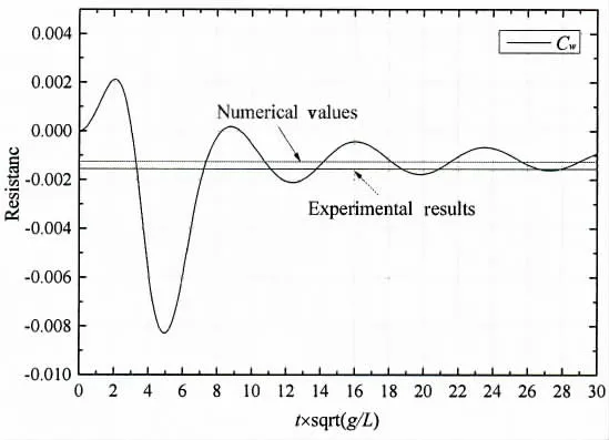
Fig.3 Time history of resistance coefficient
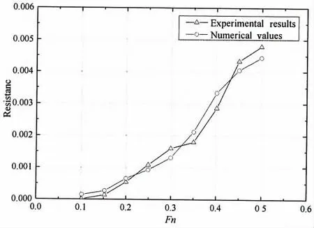
Fig.4 Resistance coefficients with different forward speed
3.2 Wigley I hull
Then the Wigley I hull is chosen as the benchmark to verify the ability of the proposed method on predicting ship motions. The experiments measurements of this hull is given by Journee[16]. The Wigley I hull is defined as

where X= (2x/L)2, Z= (z/ T)2, L=3.0 m, B=0.3 m and T=0.187 5 m.
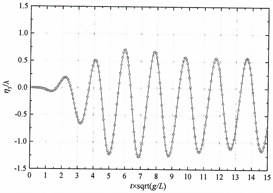
Fig.5 Time history of heave motion response

Fig.6 Time history of pitch motion response

Fig.7 Heave motion RAOs with Fn=0.2
Time histories of the heave and pitch motions computed by the current method are shown in Figs.5-6. In these figures, the half hull is discretized by 578 nodes. The wave length is λ/L=1.25, the wave amplitude is ζ/L=0.01 and the forward speed is Fn=0.2. In these calculations the time step interval is set as Δt=Te/30, where Teis the encounter wave period.
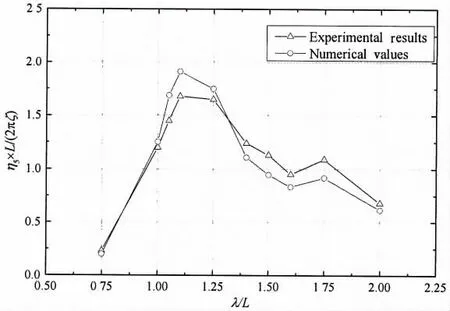
Fig.8 Pitch motion RAOs with Fn=0.2
Besides, the heave and pitch motion RAOs at forward speed Fn=0.2 in head waves are shown in Figs.7-8. The computational results give a good agreement with the model test results in general, which demonstrates the accuracy of the current scheme properly.
4 Conclusions
In this paper, a time domain 3D numerical tool for the motion and wave load simulations of 3D surface piercing bodies is newly developed, and verified through a comprehensive comparison with the published experimental measurements. The excellent level of agreement is due to several important features of the method.
First of all, the boundary integral equation is established in the earth-fixed coordinate system, so the influence of the steady velocity potential on the unsteady velocity potential can be considered automatically, which is important for the moderate and high speeds problems.Secondly, to obtain the Euler time partial derivative of the velocity potential directly, the accelerate potential is introduced which is defined as the material derivative of the velocity potential, and then solved by the same BIE as that of velocity potential. Thirdly, the higher-order description of ship hull geometry by bi-quadratic patches and continuous representation of the velocity lead to the solution of very good precision and the reduction of computing time. Finally, most of the previous studies, the indirect method corresponding to the source formulation is surprisingly used only. The present study makes use of the direct method corresponding to the potential formulation which is directly derived from the Green’s identity.
The present numerical method taking advantage of above-mentioned properties can be considered to be sound and robust as it is able to be further extended to the body-nonlinear problems.
Acknowledgement
The work is funded by the National Natural Science Foundation of China (Grant No.51709131).
- 船舶力学的其它文章
- Numerical Prediction of Propeller Noise Based on the‘Source Time-Dominant Algorithm’
- Experimental Study on Air Bleed Fusion of Underwater Vehicle
- Numerical Simulation of Cavity and Hydrodynamic Force of the Sphere Water Entry in Consideration of Surface Wettability
- Improved Moving Particle Semi-implicit Method with Large Eddy Simulation for Determining Water-entry Impact and Damage to Flat-bottomed Structures
- A Phase Modification Methodology in Modelling Deterministic Freak Wave Train
- Dynamic Response of Shipbuilding Sandwich Plate System Subjected to Impulsive Loading

