A Phase Modification Methodology in Modelling Deterministic Freak Wave Train
GAO Ning-bo, ZHANG Hong , YANG Jian-min, TIAN Xin-liang , LI Xin
(1. State Key Laboratory of Ocean Engineering, Shanghai Jiao Tong University, Shanghai 200030, China;2. Postdoctoral Research Center, CCCC Second Harbor Engineering Co., Ltd., Wuhan 430040, China;3. CCCC Highway Bridges National Engineering Research Center Co., Ltd., Beijing 100088, China)
Abstract: Freak waves, which are heated and debated in oceanic community, can pose serious damages to ships and offshore structures. Accurate simulation of the deterministic freak wave trains will be a basis for understanding wave-structure interactions. In this study, a numerical wave tank (NWT)is developed based on commercial computational fluid dynamics (CFD) software package-FLUENT.A freak wave train is given through linear superposition method. Fourier series expansion is applied to determine the amplitude and the initial phase of each wave frequency component. A phase modification methodology (PMM), by modifying the initial phases, is used to improve the numerical simulation quality. This method was validated against an elaborated experiment. It proves that the PMM can significantly improve the numerical results, which might show a new perspective in the wavestructure interaction problems.
Key words: Navier-Stokes equations; freak wave; phase modification
0 Introduction
Freak waves, also called rogue waves, have been reported frequently as human activities moving towards deep sea. Owing to the unpredictability and extremity, the freak waves may induce vital harms to ships and offshore structures. One of the most famous field records about freak waves is called ‘New Year Wave’ that occurred in North Sea in 1995[1]. Several assumptions have been proposed in the last decades to understand the evolution of freak waves, such as linear dispersive superposition, wave-current interaction, atmospheric forcing, topographic effects, nonlinear self-focusing of wave energy, etc[2-3].
Baldock et al[4]applied dispersive focusing of wave components to produce a highly nonlinear wave group in a wave tank, and found that the nonlinearity increases with the wave amplitude and reduces with increasing bandwidth. Johannessen and Swan[5]generated a large multi-direction transient wave group, and investigated the influences of spreading on large events. Wu and Yao[6]experimentally investigated the influences of current on the formation of freak waves, and found that the strong opposing current can induce partial wave blocking which significantly elevates the limiting steepness and asymmetry of freak waves. Ning et al[7]conducted numerical and experimental study on the free-surface propagation and wave kinematics for nonlinear unidirectional focused wave groups, and reported that the fully nonlinear wavewave interactions produce a much steeper wave envelope in which the central wave crest is higher and narrower, while the adjacent wave troughs are broader and less deep. Zhao et al[8]numerically simulated extreme wave groups based on VOF technique, and analyzed the nonlinearity effects on focused waves. Li et al[9]developed a numerical model based on high-order spectral (HOS) method to simulate focused waves and investigated the effects of the wave parameters on the surface elevations, the shift of the focusing points, the maximum crests and frequency spectrum.
The majority of the current studies focused on modelling extreme focused wave groups.It is not consistent with the real sea state, since it is almost static before and after the focused event. Not sufficient work is available on deterministic freak waves due to the nonlinear wavewave interaction and wave breaking. Do et al[10]used an iterative approach for Gaussian wave packet. Schmittner et al[11]proposed a phase-amplitude iteration scheme to optimize simulation of deterministic wave sequences. Buldakov[12]employed a phase-amplitude iteration scheme for tsunami wave simulation in a small wave flume. Fernández et al[13]developed a self-correcting method (SCM) to optimize the control signal of wave-maker to simulate predefined focused wave groups in a potential NWT. They validated the SCM in a large wave flume. Since the real freak wave is mostly embedded in random wave background, it will be of great significance to simulate deterministic freak wave sequences, rather than only extreme focused wave groups.
In this work, a target freak wave sequence is defined based on linear dispersive superposition theory. It serves as the input wave train to get the initial wave-maker control signals during the numerical simulation. A phase modification methodology is introduced to improve the numerical results. Then the phase modification results are validated against an elaborated experiment. The paper is arranged as follows. In Chap.1, the freak wave is defined based on linear dispersive superposition theory. The phase modificaion methodology is then presented in Chap.2.In Chap.3, the mathematic model is described which includes governing equations and numerical wave tank model, followed by numerical results and some discussions in Chap.4. Finally some conclusions are drawn in Chap.5.
1 Deterministic freak wave model
There have been a few different definitions on freak waves in the last decades. The most acceptable one was proposed by Klinting and Sand[14], which defines three parameters: (1) α=Hj/Hs≥2.0; (2) β1=Hj/Hj-1≥2, β2=Hj/Hj+1≥2; (3) μ=ηj/Hj≥0.65 (Hsis the significant wave height, Hj-1, Hj, Hj+1are the three successive waves, respectively). In this study, we adopt this definition.
In general, a real sea state is regarded as a random statistic process. In this study, JONSWAP spectrum is applied to represent a random sea, which can be given by

where α=0.062 4/ [0.23+0.033 6γ-0.185 (1.9+γ)-1], H1/3and TPare the significant wave height and spectral peak period, respectively. γ refers to the peakness parameter (the average value of γ is 3.3) and σ is the shape parameter having the values σ=0.07 if f ≤fpand σ=0.09 if f >fp; and ω=2π f.
Kriebel[15]proposed an efficient way to model freak waves by embedding an extreme wave group into a random wave circumstance, which has been widely applied in experimental and numerical studies[16-17]. It is achieved by separating the wave energy into two parts with one part going into transient wave and the other going into the underlying random background. The wave surface elevation is given by:


In this study, the significant wave height is 0.10 m, and the peak period is 2.31 s. The wave frequency bandwidth ranges are from 1 rad/s to 10 rad/s. For keeping the statistics property of the wave train, only a small part of the total energy is used to generate transient wave,which P1=0.95 and P2=0.05. The freak wave train is shown in Fig.1. The maximum wave height is 0.237 m, and it can be seen that it satisfies the definition of freak wave (see Tab.1).This defined freak wave is regarded as the target wave in the following sections. Since the nonlinearity can not be neglected in wave propagation, this wave train can not occur in the real sea state. It only serves as the input wave sequence for the numerical and experimental simulations.

Fig.1 Deterministic freak wave sequence

Tab.1 Characteristic parameters of the target freak wave
2 Phase modification methodology
Fernández et al[13]proposed a self-correcting method (SCM) to optimize the control signals of the wave-maker in a potential NWT. It has been proved that the SCM is feasible for the simulation of focused wave packages, but not for freak waves. The phase shift should be judged to be negative or positive when calculating the new control signal of the wave-maker. In order to simplify the process to calculate the new control signal of the wave-maker, we only modify the initial phases, regardless of the phase shift is negative or positive. The detailed information is given as follows.
In general, any time series of wave sequences η(t )can be represented in frequency domain by its complex Fourier transform F(ω )which is given in Eq.(3). Applying the inverse Fourier transformation, we obtain the Eq.(4)

where t is the time, and ω=2π f represents the angular frequency. In practice, it is necessary to adopt a discrete and finite form of the Fourier transform pair which is given as

where the values η (kΔ t )represent the available data points of the discrete finite wave record, Δt denotes the sampling rate and Δω=2π/ (NΔt )refers to the frequency resolution. In polar notation, the complex Fourier transform can be expressed by its amplitude and phase spectrum:

Once we get the value of F(ω )by fast Fourier transform, the associated amplitude aiand phase εican be easily calculated in Eq.(7). The wave series propagates upstream to the location of wave-maker based on linear wave theory. Then the wave-maker control signals can be given as:

where u0(t )is the velocity of the wave-maker; Tiis the transfer function associated with the ith component wave, which can be calculated as:

During wave propagation, nonlinearity such as wave-wave interaction (including sum and difference interactions) is difficult to predict. Meanwhile, wave breaking occurs for large wave steepness. It is a challenge task to model deterministic wave trains. The phase modification methodology ignores the nonlinearity effects and treats the wave propagation from wave-maker to the target position as a black box. Only the phase angles are modified. The phase modification process is presented in Fig.2 which can be divided into three steps as follows.
(1) The target wave sequence is generated at the predefined location by means of linear wave theory as Eq.(8). Thus the first recorded wave is got.
(2) The recorded wave is decomposed into number of component waves with different phase angles εrecordedthrough Fourier transformation. The phase shift between the target wave and the recorded wave is calculated as

where εsis the phase shift between εtarget, the phase angles for the target wave at the focal point,and εrecorded, the phase angles for the recorded wave at the focal point.
(3) Applying the phase shift to modify the previous wave-maker control signals

where εnewis the phase angles for the new wave-maker control signal which will be used in Eq.(8) for the next simulation, and εoldis the phase angles for the previous wave-maker control signals.
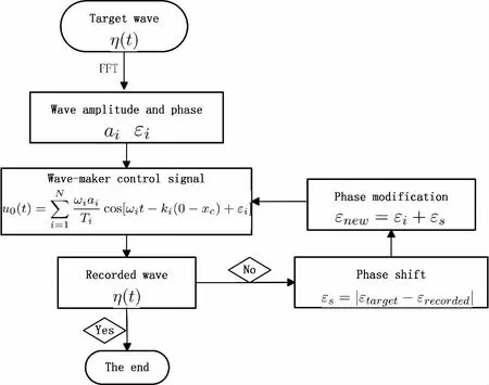
Fig.2 The diagram of phase modification
3 Mathematical model
3.1 Governing equations
In this study, we consider a laminar flow field with a free surface. The numerical simulation is carried out on a 2-D NWT. The governing equations include the continuity and Navier-Stokes equations:

The volume of fraction (VOF) method[18], is applied to capture the free surface which has been implanted in FLUENT. This method adds another governing equation of fluid fraction αq(x, y,t )given by:

where αq=0: the cell is empty (of the qthfluid); αq=1: the cell is full (of the qthfluid); 0<αq<1:the cell contains the interface. Here αq=0.5 is regarded as the free surface and its vertical coordinate which is given as surface elevation time history is extracted at the position of the wave gauges for each time step.
3.2 Numerical wave tank model
In this study, a flap wave-maker is applied and the center of rotation is hinged at the bottom. The detailed sketch of the geometric model is presented in Fig.3. Coordinate origin O locates at the left side of the wave tank bottom. The wave tank is 15 m length, with a 4 m wave absorbing zone. The water depth d is 0.9 m with 0.3 m height above the initial free surface. At x=7 m, a wave gauge is set up to obtain the time series of the wave elevation.

Fig.3 Sketch of the numerical wave tank
A wall boundary condition is set at the wave-maker and the tank bottom. At the top of the tank, a pressure boundary condition consistent with atmospheric pressure is used allowing fluid flow through the boundary. At the end of the tank, an absorbing damping zone is implemented to reduce wave reflection. In the wave absorbing zone, an attenuation coefficient c(x )is introduced to increase the flow viscosity gradually to absorb the wave reflection.

where xLand xRare the starting and the end coordinate of the damping zone, respectively.
To generate the flap wave-maker motion, dynamic layering approach is introduced. A user-defined function (UDF) written in C language is employed to control the wave-maker moving with specified velocity.
Structured grids are used to get smooth free surface. To save calculation resources as well as to improve calculation accuracy, meshes adjacent to the free surface are refined, together with coarse mesh is used in the wave absorbing zone. The mesh of the computational domain is shown in Fig.4, where the total number of the element is 78 710. The mesh model has been validated in the previous study[19].
In this simulation, we selected the pressure-based, unsteady solver and the laminar physical model in the FLUENT program. The geo-reconstruct method was applied to reconstruct the free surface. A second-order upwind discretization was chosen for better accuracy and the Pressure-Implicit with Splitting of Operators (PISO) algorithm with a neighbor correction was enabled.

Fig.4 Schematic drawing of the numerical wave tank
4 Results and discussions
The target freak wave train in Fig.1 is decomposed by fast Fourier transform. The associated wave amplitudes and phase angles are presented in Figs.5-6. It can be seen that the wave amplitude at frequency larger than 10 rad/s is negligible, which is consistent with the wave spectrum frequency bandwidth. Fig.7 shows the comparison of target freak wave and FFT decomposition result. The FFT decomposition result agrees perfectly well with the target wave.
Here, the pre-defined target wave is only regarded as the input wave series to get the initial wave-maker control signal as shown in Eq.(8). Since the wave-maker control signal is calculated based on linear wave theory during wave propagating from the focal position to the wave-maker, the numerical results must be different with the target wave considering nonlinear effects, such as wave-wave interactions and wave breaking. Then, the phase modification methodology described in Chap.3 is applied to optimize the initial phases in order to get the new wave-maker control signal.
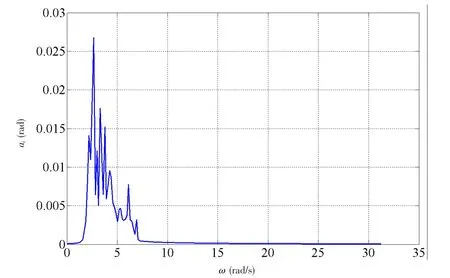
Fig.5 Wave amplitude associated with each wave component

Fig.6 Initial phase associated with each wave component
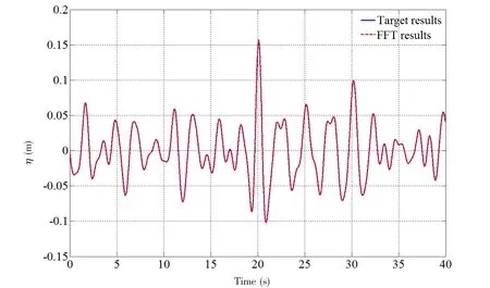
Fig.7 Comparison of target wave and FFT decomposition wave train
The numerical results will be validated with experimental data. The associated experiment was conducted in a physical wave flume in State Key Laboratory of Ocean Engineering,Shanghai Jiao Tong University. The dimension of the wave flume is 20 m×1 m×1.2 m, with a 4 m length passive wave absorbing beach at the end. The wave-maker is flap board hinged at the bottom, just as the numerical geometrical model. The flap wave-maker can move with specified velocity. The illustration is shown in Fig.8. In order to compare the numerical results and experimental data, the wave elevations at the position of 7 m away from the wave board are extracted. The initial wave-maker control signals for both numerical model and wave flume are identical, which is calcualted as Eq.(8).
In Fig.9, we can see that even though the wave-maker control signals for both numerical model and wave flume are the same, the initial numerical results show an obvious difference compared with experimental data. This difference is mainly due to the fact that the numerical model discretes the continuous flow to grid elements, which is incongruent with the property of the continuous flow. Morever, during the numerical simulation, the higher frequency components of the freak wave train will dissipate much faster than those of wave flume experiment[20].
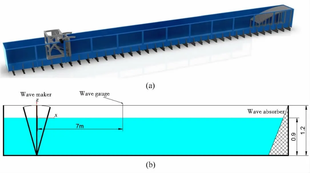
Fig.8 Schematic illustration of the wave tank (a) the 3D preview; (b) the experimental setup

Fig.9 Comparison of numerical results and experimental data
Then the initial recorded wave elevation at the target position is decomposed through fast Fourier transformation, and the phase shift can be calculated as in Eq.(10). The phase shift is applied to modify the previous wave-maker control signal as in Eq.(11). At last, the new wavemaker control signal is obtained. It can be seen from Fig.9 that the phase modification results agree quite well with the experimental data, exspecially at the maximum wave crest. The comparison of initial phases and the modified phases is presented in Fig.10. For lower frequency components (ω<8 rad/s), the initial phases and the modified phases show no obvious changes,while the modifed phases are different from the initial phases that are almost constant for higher frequency components (ω<8 rad/s). It means that higher frequency components have a significant effect on freak wave generation. Anyway, the phase modification methodology can be used to improve the numerical results, which serves as a basis for the wave-structure interaction study.

Fig.10 Comparison of initial phases and modified phases
5 Conclusions
In this study, a freak wave train which satisfies the freak wave definition is numerically simulated and compared with experimental data. In this study, we overcome the challenge induced by the nonlinearity effects during wave propagating from the target position to the wave-maker, which has not been done in previous studies. Moreover, the wave-maker transfer function is based on linear wave theory. This leads to the differences at the focusing location.In order to improve the simulation quality, a phase modification methodology is introduced to modify the phase angles during the numerical simulations. The good agreement between the numerical results and the experimental data confirms the realibility of the phase modification methodology developed in this study. This lays a foundation for the following research about wave-structure interactions, such as wave slamming and run-up.
Acknowledgement
This work is supported by the National Nature Science Foundation of China (Grant No.51239007) and China Postdoctoral Science Foundation (Grant No. 2017M612543). The sources of support are appreciated. The authors would also like to appreciate the comments from Dr.Zhao Wenhua at University of Western Australia.
- 船舶力学的其它文章
- Numerical Simulation of Flow-induced Noise of Two Circular Cylinders in Tandem and Side-by-side Arrangements Using a Viscous/ Acoustic Splitting Method
- Motions of the Floating VAWT Considering the Viscous Damping of the Spar Type Floating Foundation
- Transient Pipe Tension Influence on Dynamic Positioning Control During S-Lay Installation
- Dynamic Response of Shipbuilding Sandwich Plate System Subjected to Impulsive Loading
- Improved Moving Particle Semi-implicit Method with Large Eddy Simulation for Determining Water-entry Impact and Damage to Flat-bottomed Structures
- Numerical Simulation of Cavity and Hydrodynamic Force of the Sphere Water Entry in Consideration of Surface Wettability

