Improved Moving Particle Semi-implicit Method with Large Eddy Simulation for Determining Water-entry Impact and Damage to Flat-bottomed Structures
YANG Chao , ZHANG Huai-xin
(a. State Key Laboratory of Ocean Engineering, School of Naval Architecture, Ocean and Civil Engineering;b. Collaborative Innovation Center for Advanced Ship and Deep-Sea Exploration (CISSE), Shanghai Jiao Tong University, Shanghai 200240, China)
Abstract: The moving particle semi-implicit method (MPS) has obvious advantages for solving problems such as determining the discontinuity in water-entry impact and large structural deformation in ships. Large Eddy Simulation (LES) is an excellent method for turbulence research. Hence, this study uses the MPS-LES method to examine the fluid-structure coupling problem of simulating the waterentry impact of a flat-bottomed structure. These numerical simulations agreed closely with experimental results. Different models of structure water-entry are established with differing ribbed plate distribution to study how that influences impact deformation. Finally, the particle characteristics of the MPSLES method are utilized to evaluate the damage to the structure as preparation for the next step in the failure simulation of ship structure using MPS-LES.
Key words: moving particle semi-implicit method (MPS); fluid-structure interaction (FSI);large eddy simulation (LES); water-entry impact
0 Introduction
In the last half century, developments in science, technology, and ocean exploitation have increased the amount of research on solid structure problems occurring in ships and marine structures, in which the impact caused by a structure’s water-entry is very complicated and of practical significance. During impact, the structure interacts with the fluid, particularly in the initial stage of water entry, produces a relatively large impact load, which may result in structural deformation or damage. Thus, water-entry problems[1-4]for structures including problems involving hull slamming, green water, seaplanes, and spacecraft water landings are common in shipping and ocean engineering.
Worthington used the flash photography available at that time to observe the splash and cavitation phenomena that occurred as a ball fell into different liquids, which made him the first researcher to perform a water-entry test studying these phenomena and principles. Von Karman originally used added mass to analyze water-entry impact problems instead of fluid influence,and he proposed the use of the additional mass method to calculate water-entry impact loads.The above methods are limited to study of the water entry of rigid bodies, and most of them can only describe the overall process of water entry, which can solve few practical problems.Sharov[5]was the first to consider water-entry of an elastic body, which he separated into two parts. The first involves determining the force acting on the object by the fluid without considering the structure’s elasticity. The second calculates the elastic deformation of the object for a known surface pressure distribution. Based on Sharov’s research, Meyerhoff[6]studied the impact of water entry on an elastic structure. The water entry of a thin plate structure can show an elastic effect, and these studies were the first to solve the coupled equations for the elastic response of a structure and the impact force of the fluid. In addition, Takagi[7]used the matched asymptotic expansion method to research the water-entry problem of a two-dimensional elastic wedge plate. Then, he compared the results of a theoretical calculation with those of an experiment and found that they agreed. Lu[8]established fully coupled equations using the boundary element method for the flow field and finite element method for the structure to solve the flow field characteristics and structural responses resulting from the water entry of a two-dimensional wedge, with a constant velocity.
The water entry of a structure is a complex fluid-structure coupling process, which involves the intersection and fusion of solid mechanics, fluid mechanics, impact dynamics, and computational mechanics. At present, there are two types of theoretical methods that are used to ascertain the impact caused by water entry on a two-dimensional structure. The first is represented by Wagner’s method, which directly solves for the structural impact pressure. The second method uses numerical simulation. Although Wagner’s theory is relatively simple and practical, the scope of its application is extremely limited. The numerical method is more accurate and reliable than the theoretical method. However, when a traditional mesh method is used to calculate large deformations in fluid-structure interaction (FSI), the large deformation seriously distorts the grid, which leads to difficulties in numerical calculation and even simulation failure.
The MPS method is a new Lagrangian particle method and was first proposed by Koshizuka. After its initial appearance, MPS has been applied extensively to many research fields[9,12].Early in the development of the MPS method, many studies[13-16]focused on fluid simulation,with few studies of fluid-structure coupling problems. This happens because they met problems when they used the MPS method to handle the FSI problems. When calculating FSI problems,both the mesh method and the meshless method generally have a special processing for the interface. However, it is very difficult to handle the interface which always leads to the calculation interrupting because of the challenges that arose when using the MPS method to handle FSI problems. Considering that the MPS method is a full Lagrangian meshless particle method,fluid particles that cross a solid boundary affect the precision of numerical calculation.
The innovations of this paper are as follows. Firstly, this paper uses a bran new calculating procedure to simulate the calculation of FSI problems. The calculation process is mainly divided into two steps. The velocity and displacement of all particles (fluid particles and solid particles) are calculated using a fluid control equation; the velocity and displacement of solid particles are corrected by using the governing equations of elasticity. The biggest advantage of this method is that there is no need to identify the fluid-solid interface. It can simplify the calculation program and improve the calculation efficiency. Secondly, we add an additional correction procedure to prevent fluid particles from passing through solid boundaries. In the calculation, if the fluid particles are too close to the solid particles, an additional correction is used to keep a right distance between the fluid particles and the solid particles and at the same time the velocity of the particles is also properly corrected. Considering that correcting the velocity of the particle too much may affect the calculation, the correction value takes the sum of the difference in velocity between the particle and its neighbors. In practice, this method achieved good results. Thirdly, because of the algorithm’s own defect, the MPS method has a very serious pressure oscillation problem[17]. How to alleviate the pressure oscillation has been a difficult problem of MPS method, especially in calculating high-speed water entry. Strong pressure oscillations at the FSI terminate the simulation. In this paper we introduce a pressure iteration method that considers the calculation characteristics of the MPS, reducing the pressure oscillation and solving the Poisson pressure equation. Fourthly, to explore engineering problems that address turbulence, we used LES. Finally, we take advantage of the dominance of the MPS method’s full Lagrangian characteristics to preliminarily simulate structural damage under extreme conditions of fluid-solid coupling.
1 MPS method
1.1 Improved MPS method with large eddy simulation
The MPS method uses the continuity and Navier-Stokes equations to govern incompressible flows:

where v is the velocity vector, t is the time, ρ is the fluid density, P is the pressure, ν is the kinematic viscosity, and F is the body force vector.
To combine the MPS method with LES, we need to incorporate the SPS Reynolds stress into the MPS method. In the coordinate form, the velocity can be decomposed as follows:

where l represents the spatial orientation, v¯ is the particle scale component, and v′ is the SPS turbulence component. Then, the coordinate form of the governing equation becomes


in which νtis the kinematic eddy viscosity:

where Δ is the initial distance of the particles and Csis a constant with a value between 0.1 and 0.2 that satisfies the following equation:

This study considers 2D simulations. Thus, the last term in Eq.(5), the Reynolds stress Fspsx, can be rewritten as

In a 2D simulation, the kinematic eddy viscosity can be written as follows:

where Prin Eq.(10) can be calculated as

And k in Eq.(9) can be found as follows:

Cεand Cvin Eq.(8) and Eq.(12) are both constants. According to Eq.(8), the values of Cε, Cvand CSare:

Finally, the governing equations are formulated in the following form:

In the MPS method, particle interactions are evaluated using a weight function, such as

where r is the distance between the particles and reis the effect radius.
The particle number density is defined as follows:

which is the sum of the kernel functions of particle i and works with particles within the range of i. Vectors riand rjare the coordinates of particles i and j, respectively.
MPS uses the gradient and Laplacian models to replace terms of the governing equation,which are represented in the following form:

where d is the spatial dimension and n0is the initial particle number density. In the initial step of the simulation, vectors riand rjare the coordinates of particles i and j, respectively.
In Eq.(21), λ can be acquired as follows:

The Poisson pressure equation is obtained as follows:

where <n*>iis the number density at particle i. The Poisson pressure equation can be solved using the incomplete Cholesky conjugate gradient method (ICCG).
In computational fluid dynamics, fluid compressibility can be guaranteed by limiting the velocity divergence to zero. Substituting this condition into the Poisson pressure equation, then the relation between pressure and velocity is

Substituting Eq.(24) and the original number density into the Poisson equation yields an improved Poisson pressure equation:

In this formula, γ is the relaxation factor, which can be fixed to get better results in different calculation conditions.
The differential terms of the Reynolds stress should be processed using the boundary condition and body force. The iterative formula is written as follows:

where Δv* is the first explicit correction value of the velocity, vnis the velocity of the last time step, F is the body force, and Δt is the time increment. The temporal velocity v* and coordinate position r* are explicitly calculated by

By solving for the pressure of each particle, the correction velocity is calculated as follows:


1.2 Control equations of the elastomer
The control equations of the elastomer are as follows:

where ρsis the material density, ulis the coordinate form of the displacement vector, vl,sis the coordinate form of the velocity vector, and εlmis the strain rate tensor. The diagonal terms of εlmrepresent the elongation and contraction per unit length in the various coordinate directions and are sometimes called linear strain rates. The off-diagonal terms of εlmrepresent the shear deformations that change the relative orientation of the line segments initially parallel to the coordinate directions. Trace εrrspecifies the rate of the volume change per unit volume, δlmis the Kronecker operator, λsand μsare the Lame constants, E is Young’s modulus, and υ is Poisson’s ratio.


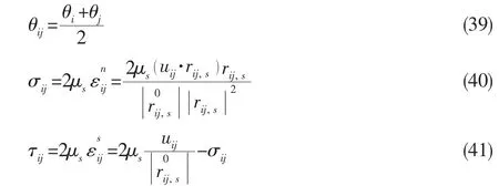

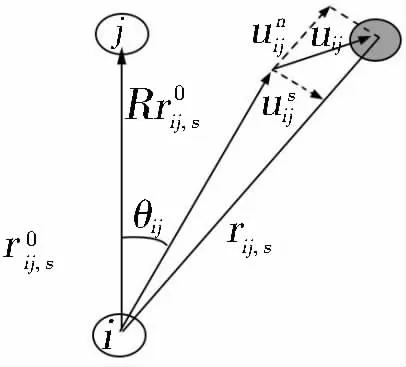
Fig.1 Relative position between particles
where σijand τijare the normal and shear stresses for particles i and j, respectively; psis an isotropic pressure obtained at the particle location. These are described by the respective formulas shown in Eqs.(39)-(41). In these formulas, d is the number of spatial dimensions. The acceleration produced by the force between particles is as follows:


1.3 Numerical simulation process
This process is adopted to deal with the fluid-structure coupling problem. The properties of the solid particles are ignored because they are treated as fluid particles. The MPS method can then be adopted for all particles. Both the speed and position of the solid particles are modified in accordance with the elastomer control equation. The specific simulation process is shown in Fig.2. This computing method does not need to process the surface between the fluid and the solid separately, which reduces the calculation costs tremendously.
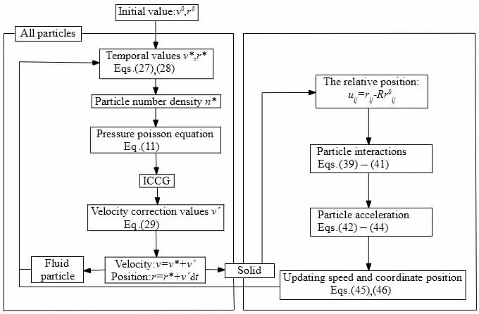
Fig.2 Algorithm of MPS simulation with fluid-structure coupling

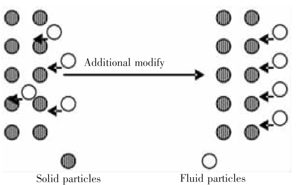
Fig.3 Additional modification
Fluid particle updates its position with a modified velocity given by the method of weighted average, then the probability of crossing is reduced. In practice, good results are obtained with this method. When a fluid particle and a solid particle are too close, velocity and position of the fluid particle are updated based on Eq.(47) and Eq.(48).

in which vrcan be written as:

And the average velocity of two particles vgis derived by Eq.(31)

2 Numerical simulation results
2.1 Numerical calculation of elastomer with fluid-structure coupling
In this study, the MPS-LES method was used to simulate the water entry of an elastomer,and to calculate the fluid-structure coupling. Fig.4 shows a model of an elastic plate impacting the water. The main parameters of the simulation are as follows. The size of the tank is 2.0 m × 1.0 m, and its depth is 0.5 m.The size of the plate is 0.4 m×0.02 m.The water entry constant velocities are 1.98 m/s, 3.13 m/s, 4.23 m/s, and 6.26 m/s, respectively. In addition, the spacing of the particles is 0.01 m.The density of the plate is 7 800 kg/m3. The numerical values of the elastic modulus and Poisson’s ratio are 2.1 × 10¹¹Pa and 0.3, respectively. The time-step used is 2.0 × 10⁻⁶s.
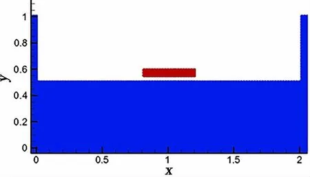
Fig.4 Elastic plate model

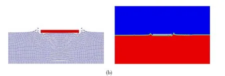
Fig.5 Process of elastic plate entering water (a) t=0.001 9 s; (b) t=0.030 s
The MPS-LES method and Ansys fluid-structure coupling results of the plate impacting the water are shown in Fig.5. We can see that the entire impact can be accurately simulated using the MPS-LES method, and with the continued impact, an increasing amount of water is drained away, leading to increasingly obvious liquid splashing at the surface. Because both the elastic plate and fluid are considered using the same method, there is no need to couple the methods, which is a considerable improvement in computational efficiency when using the MPS-LES method to solve fluid-solid coupling problems compared with the traditional grid method.
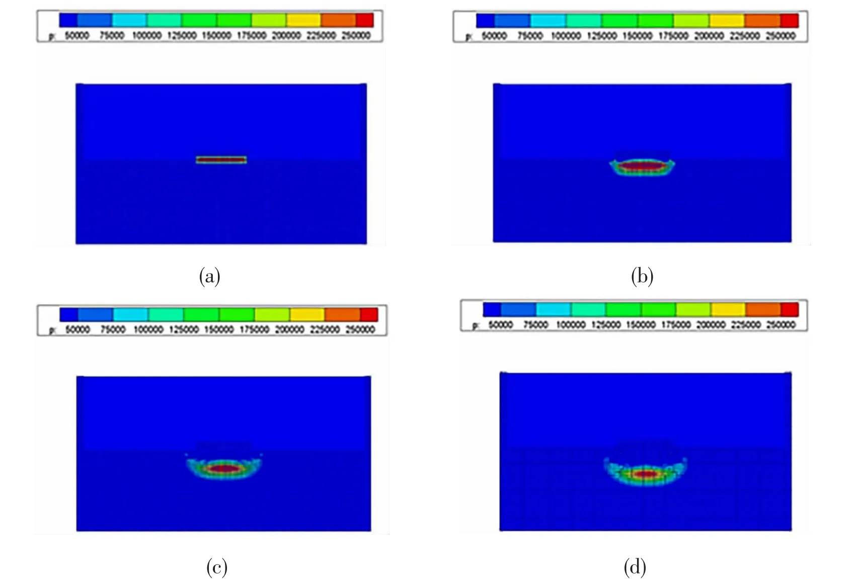
Fig.6 Instant pressure distribution for the water-entry impact of plate
Fig.6 shows a pressure distribution sequence for the numerical simulation. At t=1.9 ms,significant pressure acts on the plate. Over time, the pressure at the bottom domain increases,whereas the gap between the plate and water decreases, as shown in Fig.6(c)-(d).
The center of the plate suffers the largest slamming pressure and deformation on impact with the water. As we can see from Fig.7, the pressure load at the bottom of the plate was nearly zero before the plate was in contact with the water. However, at the moment the structure touched the water, the bottom pressure rose rapidly to the peak value and then decayed quickly.
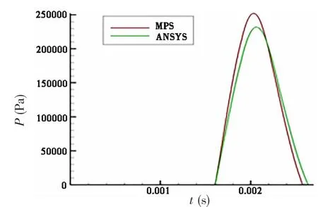
Fig.7 Pressure histories on the middle of base(v=6.26 m/s)
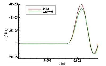
Fig.8 Deformation history of the middle of the plate (v=6.26 m/s)
For an elastic plate, the impact load from the fluid causes the structure to deform, which affects the fluid in turn. As shown in Figs.7 and 8, when the pressure on the plate reaches the peak, the deformation is maximal. Then, the deformation gradually decreases to zero. The MPS results agree with those from Ansys.
When studying special structures such as plates, we always study their deformation and pressure for a very brief time after they contact the water. The pressure peak at the center of the plate has a considerable effect on the local strength of the structure, and the value of this peak is a decisive factor in determining whether the plate breaks down. A comparison of the experimental data[20]for the peak value listed in Tab.1 with the calculation results using the MPSLES method shows that there are few differences between these two methods. Moreover, both sets of results show coherent change trends. The impact pressure peak increases with the velocity of water entry. Thus, the results are relatively accurate when using the MPS-LES method to solve fluid-structure coupling problems involving an elastic plate impacting water.

Tab.1 Comparison of simulation results and experimental results
2.2 Deformation analysis of a hollow box structure
In this section, we calculate and analyze a box structure similar to a ship’s hull. As shown in Fig.9, the size of the flat bottom was 0.3 m × 0.08 m.The density of the material was 7.8 × 10³kg/m3, and Poisson’s ratio was 0.3. The elastic flat bottom and surrounding frame had rigid connections.
Fig.10 shows the deformation curve of the midpoint of the bottom of the model with time. The velocity of water entry was 15 m/s. As shown in the figure, the deformation curve calculated by MPS was close to that calculated by MSC.Dytran[24]and Ansys.

Fig.9 Model of elastic cassette structure
Tab.2 presents the peak pressure of the box structure entering the water with three different velocities, which were compared with those calculated by MSC.Dytran[24]and Ansys.The MPS results were close to those calculated by the other methods.
Greater slamming pressure results in greater structural deformation and damage. To reduce the impact deformation of a flat-bottomed structure, we attempted to improve the structure by adding ribbed plates. The specific layouts were as shown in Fig.11.
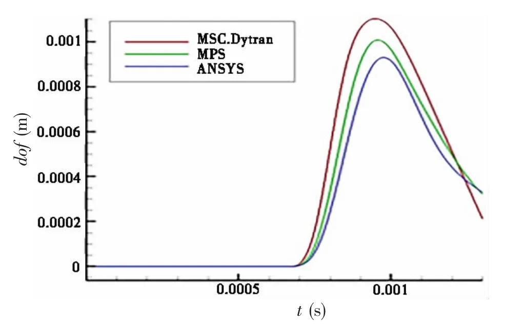
Fig.10 Deformation curves of the flat bottom with time

Tab.2 Comparison of MPS, MSC.Dytran, and Ansys results
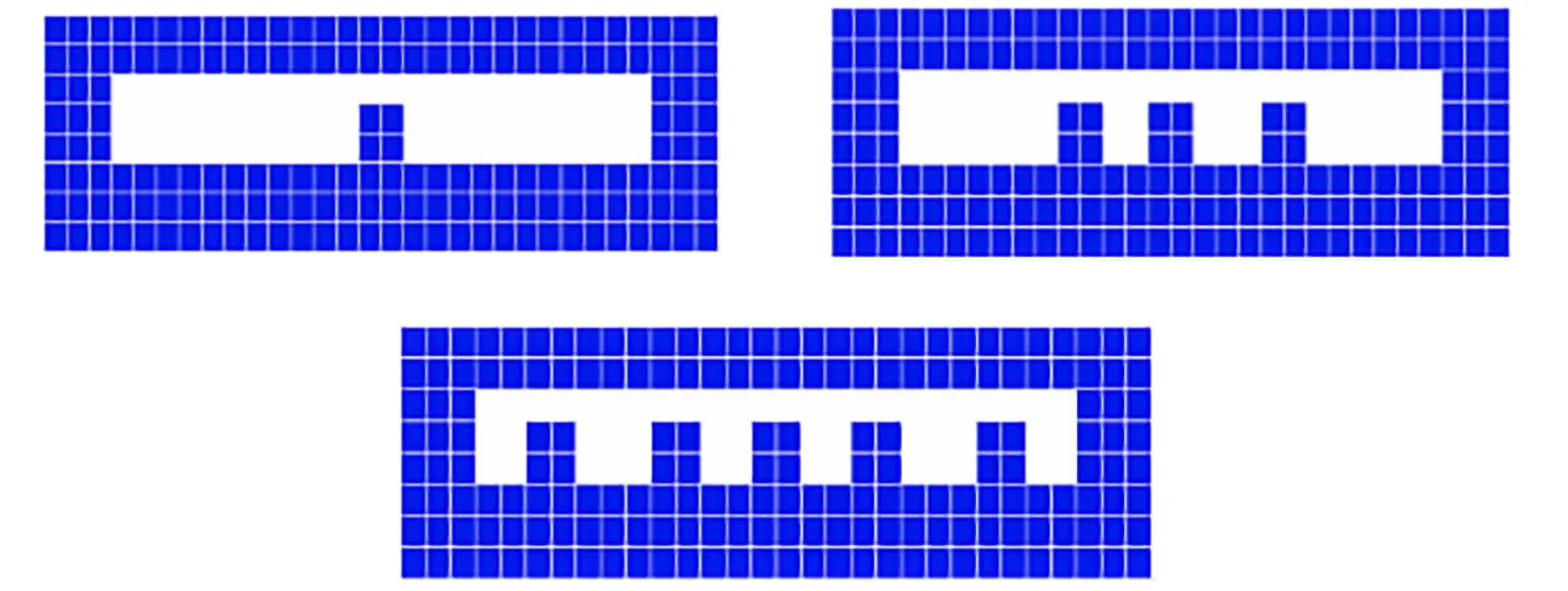
Fig.11 Layout drawings of ribbed plates
Fig.12 shows a curve diagram of the deformation of the elastic flat-bottomed structure with the addition of ribbed plates. The ribbed plates have the obvious effect of decreasing deformation in comparison with the ordinary flat bottom structure. The deformation of the plates decreases with an increase in the number of plates.
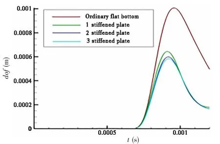
Fig.12 Improved deformation curves of flat bottom structure (15 m/s)
Tab.3 presents the peak pressure for different numbers of ribbed plates mounted on the bottom of the box structure. The ribbed plate has almost no effect on peak pressure without affecting the slamming pressure, but structural deformation was reduced. Therefore, setting ribbed plates can significantly improve the safety of the structure.

Tab.3 Peak pressure when different numbers of ribbed plates mounted on the bottom of the box (15 m/s)
2.3 Simulation of impact failure of a flat plate
When a ship is sailing on waves, there is a considerable impact at the time it enters the water, which may cause the structure of the ship to deform or may even damage or destroy the structure. Shipwreck often occurs because of slamming. Thus, it is very important to study the problem of impact failure during water entry. It is very difficult to calculate the large deformation and failure of a structure using the traditional grid method because of the frequent errors caused by grid distortion. MPS-LES can very conveniently be used for FSI problems such as plate slamming and damage. It can directly compute solutions without any special treatment.Thus, this method has a broad prospective applicability to damage problems.
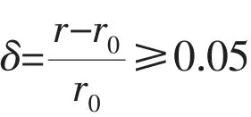
The velocity of the flat plate entering the water was 10 m/s. In the following figures, we show two situations in which the structure is ordinary or enhanced with ribbed plate.
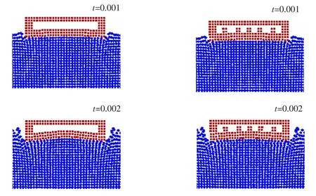
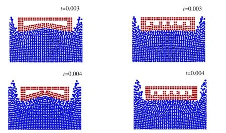
Fig.13 Image comparison between an ordinary flat-bottomed structure and an improved one
The strain at the center of the bottom of the plate is the largest when the flat plate slams into the water. Therefore, structural damage usually occurs there. As shown in Fig.13, structural failure occurs at the center of the bottom of the flat plate. Thus, the calculation results are consistent with the physical phenomena. In contrast, after the installation of ribbed plates under the same slamming pressure conditions, the impact has little influence on the structure, and causes little damage, demonstrating the benefit of adding ribbed plates to reduce deformation and prevent structural damage, which effectively improves the safety of ship navigation.
3 Conclusions
This study used MPS-LES to simulate fluid-structure coupling of a flat-bottomed structure impacting water. From the numerical simulations, the following conclusions can be drawn:
(1) Because of the limitation of the grid, the traditional mesh method can only simulate the contours of free surface deformation. However, the MPS-LES method can accurately simulate the splashing of water particles, and the calculation efficiency of the MPS-LES method is obviously higher than that of the traditional mesh method.
(2) By comparing the results calculated by MPS-LES with experimental results and those calculated by other numerical simulations, the results derived from the MPS-LES method are credible. The peak pressure and large deformation of the flat structure can provide a theoretical basis for the design of elastic structures.
(3) The installation of ribbed plates has no effect on the peak pressure of the flat structure, but deformation was significantly reduced. Therefore, the installation of ribbed plate improves the structural rigidity and safety.
(4) Structural damage to the flat structure occurs at the midpoint of the bottom of the structure at the initial time of water entry.
- 船舶力学的其它文章
- Numerical Simulation of Flow-induced Noise of Two Circular Cylinders in Tandem and Side-by-side Arrangements Using a Viscous/ Acoustic Splitting Method
- Motions of the Floating VAWT Considering the Viscous Damping of the Spar Type Floating Foundation
- Transient Pipe Tension Influence on Dynamic Positioning Control During S-Lay Installation
- Dynamic Response of Shipbuilding Sandwich Plate System Subjected to Impulsive Loading
- A Phase Modification Methodology in Modelling Deterministic Freak Wave Train
- Numerical Simulation of Cavity and Hydrodynamic Force of the Sphere Water Entry in Consideration of Surface Wettability

