Development and Application of a Hi gh-Performance Triangular Shell Element and an Explicit Algorithm in OpenSees for Strongly Nonlinear Analysis
Xinzheng Lu ,Yuan Tian,Chujin Sun and Shuhao Zhang
Abstract: The open-source finite element software,OpenSees,is widely used in the earthquake engineering community.However,the shell elements and explicit algorithm in OpenSees still require further improvements.Therefore,in this work,a triangular shell element,NLDKGT,and an explicit algorithm are proposed and implemented in OpenSees.Specifically,based on the generalized conforming theory and the updated Lagrangian formulation,the proposed NLDKGT element is suitable for problems with complicated boundary conditions and strong nonlinearity.The accuracy and reliability of the NLDKGT element are validated through typical cases.Furthermore,by adopting the leapfrog integration method,an explicit algorithm in OpenSees and a modal damping model are developed.Finally,the stability and efficiency of the proposed shell element and explicit algorithm are validated through the nonlinear time-history analysis of a highrise building.
Keywords: Triangular shell element,explicit algorithm,OpenSees,strong nonlinearity.
1 Introduction
The performance of structures against extreme hazards has become an important research topic.By discovering the damage evolution process and failure mechanism,the research outcomes will support the identification and optimization of vulnerable structures.In addition to physical experiments,numerical simulations based on the finite element method,as an important and effective approach,have been widely used [Nesnas and Abdul-Latif (2001);Bradford and Pi (2012);Lin,Li,Lu et al.(2016)].Thus far,strongly nonlinear analyses of structures have been performed extensively,and corresponding simulation strategies have been proposed [Lu,Lu,Guan et al.(2013);Lu,Tian,Cen et al.(2018)].OpenSees,as an open-source finite element software,is now widely used owing to its high transparency and freedom [McKenna,Scott and Fenves (2009)].For strongly nonlinear problems,on the one hand,the elements must consider the material and geometric nonlinearity simultaneously;on the other hand,the time integration algorithm should be sufficiently stable during the entire computational process.However,further improvement on these two aspects is still required in OpenSees.
In terms of element technology,a typical modeling strategy for the nonlinear analysis of buildings is to adopt fiber elements for beams/columns and shell elements for shear walls and coupling beams [Lu and Guan (2017)].In OpenSees,the collapse simulation of frame structures has been performed successfully by using fiber elements [Lignos,Chung,Nagae et al.(2011);Xie,Lu,Guan et al.(2015)].However,it would be difficult for the fiber elements to represent the axial-flexural-shear coupled behavior of shear walls.Therefore,based on the generalized conforming theory,Lu et al.[Lu,Tian,Cen et al.(2018)] proposed and successfully implemented a quadrilateral flat shell element,NLDKGQ,into OpenSees.Subsequently,they performed a collapse simulation of a highrise reinforced concrete (RC) frame-core tube building using NLDKGQ.The NLDKGQ element,consisting of the plate element DKQ and the membrane element GQ12,can avoid shear locking.By introducing the updated Lagrangian formulation,NLDKGQ can simulate the geometric nonlinearity and is suitable for large deformation problems.However,NLDKGQ is not adaptable to triangular meshes;therefore,it is not easy to adopt the NLDKGQ element for the cases with complicated boundaries or curved surfaces.In contrary,triangular shell elements are more adaptive to complicated boundaries,and they can effectively solve mesh distortion and warpage problems.Therefore,it is necessary to propose a triangular shell element for OpenSees.
In terms of the time integration algorithm,two types of algorithms exist:implicit algorithm and explicit algorithm.The implicit algorithm is typically used,but a convergence test is essential at each time step.It is noteworthy that the implicit algorithm may fail to perform a complete analysis owing to its strong nonlinearity-induced nonconvergence.Therefore,explicit algorithms are preferred for strong nonlinearity [Lu,Lin,Cen et al.(2015);Pham,Tan and Yu (2017)],which can avoid convergence problems.Among the existing explicit algorithms,the central difference method is the most popular one.Theoretically,the central difference method can be highly efficient when the system of equations can be decoupled.However,the decoupling criterion for the central difference method requires a diagonal damping matrix.The mass-proportional damping matrix is diagonal,but it obviously underestimates the damping ratio of high-order modes and consequently does not yield a satisfactory accuracy [Xie (2015)].In contrast,if the stiffness-proportional damping model is introduced to restrain high-order modes,the system of equations would fail to decouple,leading to an increased computational time.
To solve the problems above,researchers have proposed numerous solutions.For example,Li et al.[Li,Liao and Du (1992)] derived an explicit difference method for viscoelastic dynamic equations;Du et al.[Du and Wang (2000)] derived an explicit integration formula for damped elastic lumped-mass structures.However,although the algorithms proposed by Li et al.[Li,Liao and Du (1992)] and Du et al.[Du and Wang (2000)] can ensure the decoupling of the system of equations,the equations for displacement and velocity are required to be established and solved separately at each time step,which significantly increases the computational time.
Consequently,based on the generalized conforming theory and the updated Lagrangian formulation [Long,Cen and Long (2009)],a new triangular shell element NLDKGT is proposed in this work that is suitable for cases with complicated boundary conditions and problems with strong nonlinearities.Furthermore,by adopting the leapfrog integration method,an explicit algorithm in OpenSees and a modal damping model are developed in this work.The explicit integration algorithm can ensure the decoupling of the system of equations.The accuracy and reliability of the triangular shell element are validated through typical cases.Finally,the stability and efficiency of the proposed shell element and the explicit algorithm are validated through the nonlinear time-history analysis of a high-rise building.
2 A new triangular shell element NLDKGT
2.1 Basic formulation under small deformation
To develop a suitable triangular shell element,the triangular planar membrane element GT9 [Xu and Long (1993)] and the triangular thin plate element DKT [Batoz,Bathe and Ho (1980)] were used to construct the new triangular shell element in this work.The planar membrane element GT9 contains three degrees of freedom (DOFs) at each node by introducing a rigid rotational freedom.In addition,a higher accuracy is achieved by defining higher order displacement fields [Xu and Long (1993)].The plate element DKT is based on the Kirchhoff theory and can effectively avoid shear locking.Fig.1 illustrates the decomposition of the NLDKGT element.Consisting of GT9 and DKT,the NLDKGT has six DOFs at each node.This will greatly reduce the connection modeling workload among the shell and the beam/column elements.
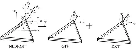
Figure 1:Decomposition of NLDKGT element
The nodal displacement q is defined as follows:

Here,qimand qibdenote the nodal displacement components of GQ9 and DKT,respectively.They can be expressed as follows:

The displacement u of GQ9 can be obtained through superposition of u0and uθas shown in Eq.(4).Here,u0denotes the linear part of the displacement field,while uθis an additional rotation displacement.Through Eqs.(5) to (8),u0and uθcan derived [Xu and Long (1993)].

where
Here,Ais the area of GT9 element;ai=xjym-xmyj,bi=yj-ym,ci=xm-xj,and (xi,yi) is the coordinate of nodeiin GT9 element in the local system.Then,Eqs.(9) and (10) are adopted to solve the strain εm.

where

The stiffness matrix of GQ9 is as follows:

Here,Dmmrepresents the material matrix of GQ9 element.Generally,if the element is made of isotropic linear elastic materials,Eq.(12) can be adopted to derive Dmm.In Eq.(12),Erepresents the elastic modulus,hrepresents the element thickness,andνrepresents Poisson’s ratio.

Eq.(3) defines the rotational DOFs of the DKT element [Batoz,Bathe and Ho (1980)].
The relation between nodal displacements qband rotational strain χbis as follows:

Details on Hxand Hyare available in Batoz et al.[Batoz,Bathe and Ho (1980)].
The stiffness matrix of DKT is as follows:

Here,Dbbdenotes the material matrix of DKT.Generally,if the element is made of isotropic linear elastic materials,Dbbcan be derived as:

For small deformations,based on the plate stiffness matrix Kband the membrane stiffness matrix Km,the local stiffness matrix of the NLDKGT element can be derived according to the DOF sequencing in Eq.(1).Then,the global element stiffness matrix can be obtained through coordinate transformation.
2.2 Geometric nonlinearity
At each time stept,through the updated Lagrangian formulation,the current deformation can be adopted to update the stresses and strains in incremental forms.Based on Kirchhoff’s and von Karman’s assumptions [Podio-Guidugli (1989)],a linear part (Δe) and a nonlinear part (Δη) constitute the shell element strain increment (Δε).The linear part (Δe) can be derived from plate rotational strain increment Δχband membrane strain increment Δεm,as shown in Eqs.(16) and (17),respectively.


Fromttot+ dt,Eq.(18) is adopted to update the shell element stress tensor:
Here,at timet,Dtanis the tangential constitutive matrix.In the local coordinate system of the shell element,the system of equations using the updated Lagrangian formulation is as follows:

Here,t+dtF andtR represents the external and internal force vector,respectively;the subscript represents the time step.In terms of the stiffness matrix,Klis the linear part and Knlis the nonlinear part,which can be obtained through Eqs.(20) and (21),respectively.

Here,by integrating Dtanthrough the element thickness as shown in Eq.(22),Dmm,Dmb,Dbm,and Dbbcan be solved.Using the bending plate element interpolation function,the matrix G can be derived [Batoz,Bathe and Ho (1980)].Variables corresponding to the membrane element internal force vector constitute the matrix(Eq.(23)).

Eq.(24) can be used to solve the elemental internal force vectorin Eq.(19):

where

2.3 Implementation in OpenSees
Under the class ofshellin OpenSees,a new class namedShellNLDKGTis added.During the implementation of the NLDKGT,nearly no source code change is made beyond the shell element domain.Through the official website of OpenSees (http://opensees.berkeley.edu),users can download corresponding source code of the NLDKGT element.
It is worth noting that,the proposed NLDKGT element is compatible with other elements in OpenSees.Thus,for a real finite element model,users can use the NLDKGT elements in complicated boundary areas,and use other four-node shell elements in regular-shaped areas.
2.4 Validation through classical benchmarks and RC specimens
In this section,three classical numerical benchmarks (Sections 2.4.1 to 2.4.3),one buckling analysis of an H-shaped beam (Section 2.4.4),and the simulation of two reinforced concrete (RC) shear wall specimens (Section 2.4.5) are used for the performance validation of the triangular shell element NLDKGT.For the convenience of discussion,all parameters in the classical benchmarks (Sections 2.4.1 to 2.4.3) are nondimensional,while the units of the parameters in Sections 2.4.4 and 2.4.5 keep the same with the real components.
2.4.1 Scordelis-Lo roof problem
The Scordelis-Lo roof problem is shown in Fig.2.The cylindrical panel is loaded vertically by a uniform dead weight ofg=90.The panel is supported by end diaphragms but the sides are free.Owing to the symmetry,only one quarter of the panel is established.Three types of meshes were adopted in this analysis,as listed in Tab.1.The vertical deflection at pointAwas recorded.For this case,the geometric nonlinearity was not considered.
The exact solution of 0.3024 provided by MacNeal and Harder [MacNeal and Harder (1985)] was used as a reference.The results obtained using the DKT-CST-15RB element [Nicholas,Henryk and Ted (1986)] and OLSON element [Olson and Bearden (1979)] were compared with the results obtained using the NLDKGT element.The DKT-CST-15RB element is a superposition of the DKT plate bending element and the CST plane stress element,with 15 DOFs [Nicholas,Henryk and Ted (1986)].The OLSON element is an 18-DOF flat triangular shell element reformulated by combining a bending triangle with a plane stress triangle incorporating in-plane rotations at each vertex [Olson and Bearden (1979)].Tab.1 shows the comparison results.The NLDKGT element is more accurate compared to the other two elements.
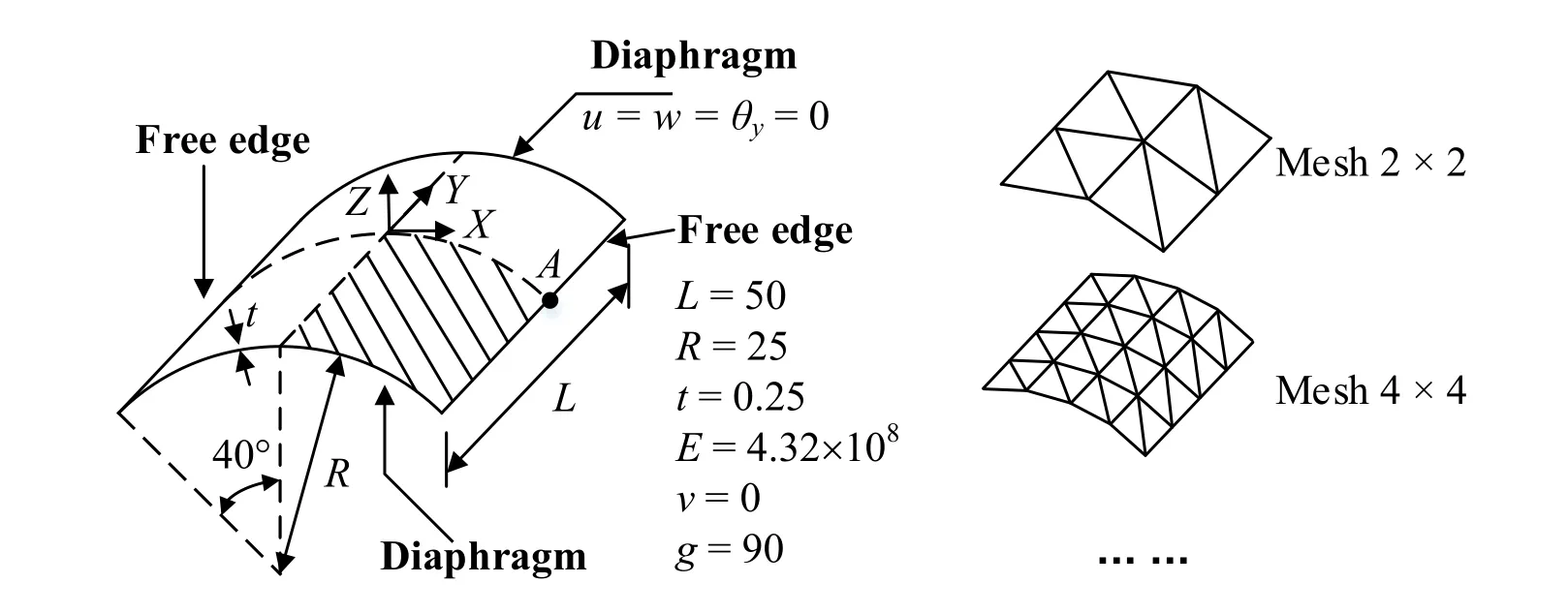
Figure 2:Scordelis-Lo roof problem

Table 1:Comparison of results for Scordelis-Lo roof problem
2.4.2 Twisted beam problem
Fig.3 shows the twisted beam problem [MacNeal and Harder (1985)].A concentrated load is applied at the tip along the in-plane (P) and out-of-plane (Q) directions,respectively.A mesh of 2×12 was adopted in this problem.Two load cases were analyzed:(1)P=1,Q=0;and (2)P=0,Q=1.The displacement along the loading direction at the tip was recorded.For this case,the geometric nonlinearity was not considered.
The exact solutions provided by MacNeal et al.[MacNeal and Harder (1985)] were used as a reference.Tab.2 shows the results of the comparison and illustrates the accuracy of the NLDKGT element.

Figure 3:Twisted beam problem
2.4.3 Large deformation problem of a cantilever beam
To validate the geometric nonlinearity simulation capacity of the NLDKGT element,a cantilever beam subjected to a pure bending load (out-of-plane) is analyzed [Horrigmoe and Bergan (1978);Park,Cho and Lee (1995)],as shown in Fig.4.The mesh of 1×10 is adopted.Fig.5(a) shows the relationship between the normalized moment (κ=M/Mmax) and the horizontal and vertical displacements at the loading point.Fig.5(b) shows the deformed shape of the cantilever beam under different bending moments.The results show that the NLDKGT element can simulate the large deformation and rotation problems with good accuracy,which is similar to the S4 element in ABAQUS.Such a large deformation capacity makes the NLDKGT element highly suitable for geometric nonlinearity problems.

Figure 4:A cantilever beam subjected to a bending moment at the end
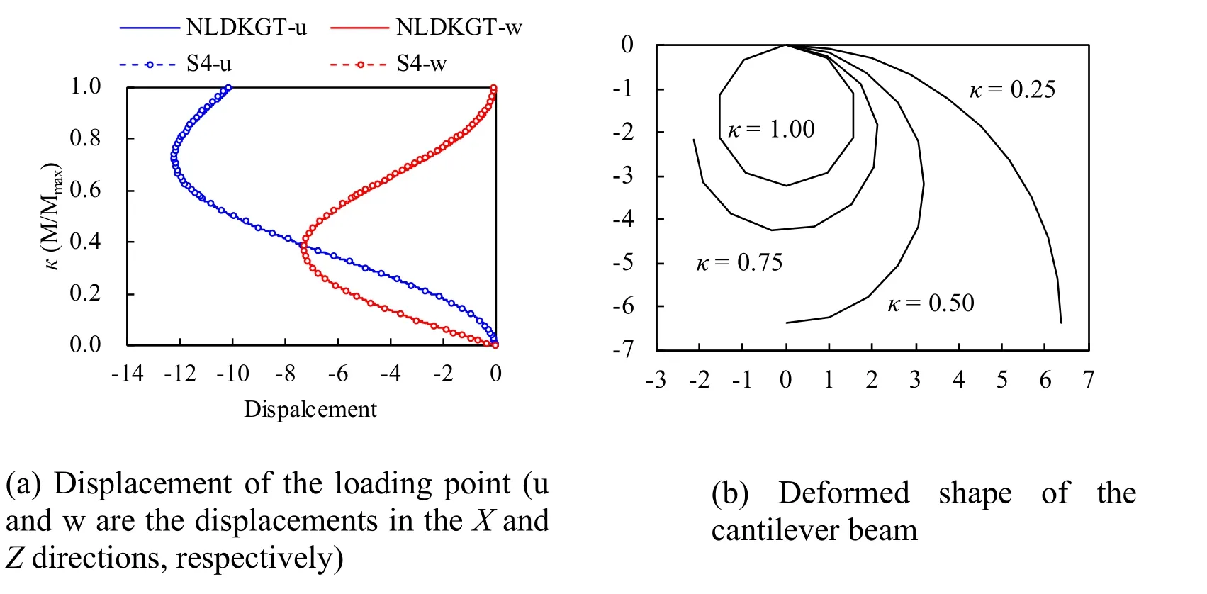
Figure 5:Deformation of the cantilever beam
2.4.4 Buckling analysis of an H-shaped beam
An H-shaped beam shown in Fig.6 is used to demonstrate the buckling analysis.An isotropic elastic material (E=2.06×10¹¹Pa,ν=0.3) is used for the beam.Both the NLDKGQ and NLDKGT elements were adopted in this analysis,and the corresponding meshes are shown in Fig.6.The two ends of the H-shaped beam were simply supported.In finite element simulations,initial defects (e.g.,initial bow imperfections leading to additional moment to the middle of components) are theoretically necessary to simulate the buckling phenomenon.According to the recommendations in EN 1993-1-1 [CEN (2005)],a distributed load ofp=0.5 N was imposed at each node on the web of the Hshaped beam to simulate the initial defects.Subsequently,a pressure load was applied at the top of the H-shaped beam,and the relation between the vertical load and displacement along the loading direction was recorded,as shown in Fig.7.
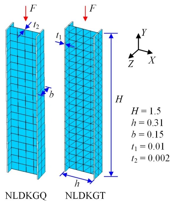
Figure 6:H-shaped beam for buckling analysis (Unit:m)
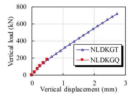
Figure 7:Force-displacement relation at the top of H-beam
As shown in Fig.7,the model using NLDKGQ fails to converge when the imposed load approaches 200 kN,i.e.,when the H-shaped beam just begins to buckle.This phenomenon is due to the warping of the quadrilateral shell element.In contrast,a stable result is obtained using the triangular shell element NLDKGT.Fig.8 shows the deformation of the H-shaped beam along theZdirection.The blue and red solid lines denote the deformation shape using the NLDKGT and NLDKGQ elements,respectively,at the time step when NLDKGQ fails to converge.The dashed blue line denotes the final deformation of the model using the NLDKGT element.Through the analysis of this case,the NLDKGT element is proven as more stable and reliable than the NLDKGQ element for the buckling analysis.
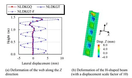
Figure 8:Deformation of H-shaped beam
2.4.5 RC shear wall experiments
To investigate the performance of the NLDKGT element in simulating RC specimens,the hysteretic behavior of two shear wall specimens is analyzed using OpenSees based on the multilayered shell section model [Lu,Xie,Guan et al.(2015)] and the NLDKGT element.The test specimens include one rectangular wall (denoted as SW1-1) [Zhang (2007)],and one coupled wall (denoted as CW-3) [Chen and Lu (2003)].The meshing schemes and corresponding hysteretic curves are shown in Fig.9.The comparisons between the test and simulation results indicate that the NLDKGT element can provide satisfactory simulation results in the nonlinear behavior of RC shear walls.
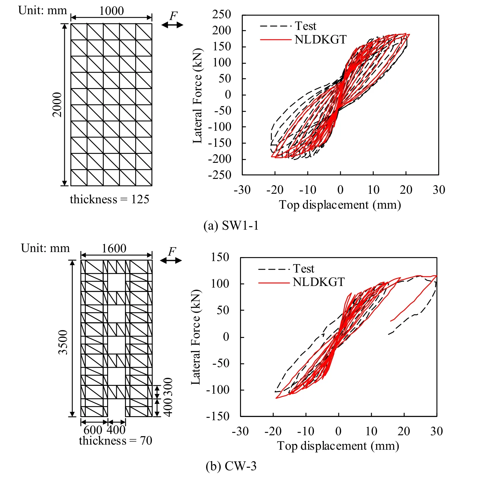
Figure 9:Lateral force versus top displacement hysteretic curves of RC shear walls
3 Explicit algorithm and its implementation in OpenSees
Eq.(27) shows the equations of motion for a structural system.After adopting the central difference method,Eq.(27) can be expressed as Eq.(28).

where M and C are the mass and damping matrices of the system,respectively;R and P are the resisting and external force vectors of the system,respectively;u,,and ü denote the displacement,velocity,and acceleration,respectively;the subscript denotes the time.
It is difficult to decouple the equations if C is not a diagonal matrix.To avoid this problem,most researchers adopt the mass-proportional damping model for the central difference method.However,mass-proportional damping will underestimate the damping ratio of high-order vibration modes,which sometimes leads to unreasonable results.
3.1 Leapfrog integration method
The leapfrog integration method [Hockney (1970)] is an improved format proposed based on the Verlet integration method [Verlet (1967)].In the leapfrog method,the equations for updating velocity and displacement are as follows:

To adopt the leapfrog method,Eq.(27) and Eqs.(29)-(30) must be solved simultaneously.The velocity and displacement are not defined at the same time step.Thus,at first,in Eq.(27) is replaced withto perform the computation,which is equivalent to the backward difference format for velocity.Subsequently,Eq.(27) can be expressed as follows:

Substituting Eqs.(29)-(30) and Eq.(32) into Eq.(31) yields

Eq.(33) shows that the system of equations can be decoupled when the mass matrix is diagonal.However,in this method,the kinetic and potential energies of the system are not defined at the same time step,leading to a failure in calculating the total energy directly.To solve this problem,certain additional steps are added to revise the algorithm.The entire process of the revised format is as follows [Sandvik (2018)]:(1) First,calculate ut+Δtthrough Eq.(33);
(3) Solve ütusing the newly obtained:

(4) Solve ut+Δtusing Eqs.(29)-(30).
The revised format above was performed through an iterative process.However,the additional computational cost is still relatively small,because the equations are simple.In addition,the revised format will provide the velocity and displacement at the same time step and is convenient to calculate the total energy at each time step directly.
Because the backward difference format is adopted for the velocity,the stability criterion of the algorithm is different from the central difference method.Here,the conclusion will be given directly as follows (more details are provided in Appendix A):

where,ωnis the highest angular frequency of the system;Tnis the shortest period of the system;ζis the damping ratio corresponding toωn.Eq.(35) shows that the numerical stability of the algorithm is not only related to the system frequency but also to the damping ratio.
For a finite element model,the shortest periodTncan be determined by solving generalized eigenvalues of the system.But,to simplify this procedure,an additional method is often adopted:to solve the shortest period of each element (denoted as min(Tn(e))) [Wang (2003)].It has been proved that,the substitute period min(Tn(e)) is always not longer thanTn.The min(Tn(e)) for each element is usually approximately estimated by usingπL/C.Here,Lis the characteristic length of the element;Cis the wave speed.These parameters may differ for different kinds of elements.
For example,for truss and beam elements,Lis the length of the element,andCcan be taken aswhereEis the Young’s modulus,andρis the mass density.For shell elements,three kinds ofLare provided by Hallquist [Hallquist (2006)],andCcan be taken aswhereνis the Poisson’s ratio.
Although different estimation methods can be found for min(Tn(e)),the basic concept is identical:The stable time step will be smaller for models with smaller element sizes and larger stiffness.Therefore,appropriate meshing schemes should be adopted for models using explicit algorithms.
The explicit algorithm above was implemented in OpenSees through a new class calledExplicitdifference,which falls under the class ofIntegrator.The new algorithm fits the OpenSees framework.The source code of the method is available at the official website of OpenSees (http://opensees.berkeley.edu).
3.2 Damping model adopted in explicit algorithm
To avoid a high computational cost,restrain unreasonably high frequency vibrations,and ensure the equations to be decoupled,it is necessary to use the superposition of the modal damping and mass-proportional damping models.Thus,the modal damping model was implemented in OpenSees.The modal damping can be expressed as follows [Clough and Penzien (2003)]:

where Cmis the modal damping matrix;M is the mass matrix;mn,ζn,ωn,and φnare the modal mass,modal damping ratio,natural vibration frequency,and mode shape corresponding to thenth mode,respectively.The damping model that this work adds to OpenSees ensures that the superposition of the damping ratios from the modal damping,and the mass-proportional damping of each vibration mode is equal to the assigned total damping ratio.
4 Collapse simulation of a high-rise RC frame-core tube building
In this section,a 42-story RC frame-core tube building with a height of 141.8 m (Fig.10) (denoted as Building 2N by Lu et al.[Lu,Xie,Guan et al.(2015)]) was simulated using OpenSees.More details about this building are provided by Lu et al.[Lu,Xie,Guan et al.(2015)].The beams and columns were simulated with fiber beams.The shell element combined with the multilayered shell section was adopted to model the shear walls.Hence,both the material and geometric nonlinearity can be considered.The shear walls in this high-rise building are of regular shapes.In this work,coupling beams of the core tube were simulated using NLDKGT,while other shear walls were modeled using NLDKGQ.

Figure 10:Three-dimensional view and typical layout of Building 2N (units:mm) [Lu,Xie,Guan et al.(2015)]
First,the El-Centro 1940 ground motion was adopted as the input along theXdirection.The peak acceleration was adjusted to 5.1 m/s2(2% probability of exceedance in 50 years,as defined in the Chinese code [CMC (2010)]).According to the mesh size,material property,and element size,the time step was set to 4×10⁻⁵s for the explicit algorithm,and 0.01 s for the implicit algorithm.Tab.3 provides the information of the analyzed cases.

Table 3:Case information for Building 2N
Fig.11 shows the comparison of the roof displacement time history.The results of the Ex-MS+MD model agree well with that of the Im-RL model (using the implicit algorithm and the Rayleigh damping).The results of the Ex-MS+MD10 model are sufficiently accurate,while the results of the Ex-MS+MD30 model are smoother.This implies that,in this case,the modal damping of the first 10 vibration modes is sufficient to avoid unreasonably high frequency vibrations.In contrast,significant variations exist when only the mass-proportional damping model is adopted (i.e.,the Ex-MS model).The results of the Ex-MS model underestimated the damping ratio of high-order vibration modes.Consequently,the contribution of the high-order vibration model to the structural deformation cannot be ignored.
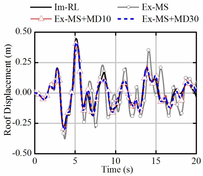
Figure 11:Time history curves of roof displacements in Building 2N
Fig.12 shows the comparison of the inter-story drift ratio (IDR) envelop.Similar to the findings in Fig.11,the superposition of the mass-proportional and modal damping (i.e.,the Ex-MS+MD model) will provide similar results to the implicit algorithm using the Rayleigh damping (i.e.,the Im-RL model).However,if only the mass-proportional damping model is adopted,the IDR results are much greater.
For large-scale engineering structures,the fundamental periods are relatively long.Consequently,the high-order vibration modes contribute significantly to the structural responses.Thus,the mass-proportional damping model alone,to some extent,is not suitable for large-scale structures.It is more appropriate to adopt the superposition of the modal damping and mass-proportional damping models to avoid unreasonably high frequency vibrations.

Figure 12:Inter-story drift envelope of Building 2N
An incremental dynamic analysis (IDA) was performed using the Ex-MS+MD10 model,and the peak accelerations were adjusted to 5.1 m/s2,20 m/s2,40 m/s2,and 50 m/s2,respectively.Here,20% of the initial slope is used to find the collapse intensity [FEMA (2000);Jalayer (2003);Villaverde (2007)].According to the criterion above,Building 2N will collapse when the peak acceleration of the El-Centro record is larger than 40 m/s2.

Figure 13:IDA results
Tab.4 shows the efficiency comparison among different cases in Tab.3 and an additional case (explicit algorithm+Rayleigh damping).Among all the cases using the explicit algorithm,the Ex-MS,and Ex-MS+MD models both require the least computational time cost.However,when the Rayleigh damping model is adopted for an explicit algorithm,the time cost becomes much larger (approximately three times that of the Ex-MS model).The primary reason of this phenomenon is that,the Ex-RL model spends significantly more time on the damping matrix contributed by the stiffness matrix at each time step.The total computational cost of the two cases using the implicit algorithm is less than that of the explicit algorithm.It is noteworthy that,when the implicit algorithm is adopted to perform the collapse analysis (i.e.,the Im-RL2 model),the computational time will increase significantly.This is because the number of iterations will increase significantly when the structural components enter strong nonlinearity.Even with a larger convergence tolerance,the average time cost at each step is still 2.4 times that of the Im-RL1 model (which has a smaller ground motion intensity).The explicit algorithm does not require any iteration.This advantage means that the time cost of the explicit algorithm is proportional to the number of time steps.Thus,for strongly nonlinear problems,compared with the explicit algorithm,the implicit algorithm requires more time cost,and sometimes demonstrates no satisfactory results because of convergence failure.
Although the Ex-MS model also demands less computational time,its results are not accurate because the mass-proportional damping alone cannot control the unnecessary high-order vibration.Thus,the Ex-MS+MD model is the best option for the collapse analysis of this building.

Table 4:Computational efficiency of each case
5 Conclusions
For strongly nonlinear analysis,the element and time integration algorithm are two important challenges.However,the shell elements and the explicit algorithm in OpenSees still require further improvements.Therefore,a triangular shell element NLDKGT and an explicit algorithm are proposed and implemented in OpenSees in this work.The conclusions are as follows:
(1) Through the validation of classical benchmarks,the triangular shell element NLDKGT was proven accurate and reliable.Compared with the quadrilateral element,the NLDKGT element could not only well consider the geometric nonlinearity,but also exhibited great advantages in strong nonlinear and warpage problems,such as buckling analysis.In addition,it is more flexible to use NLDKGT elements in complicated boundary areas to avoid mesh distortion;
(2) An explicit algorithm,along with a modal damping model,was implemented into OpenSees based on the leapfrog method.Through the nonlinear time history analysis of a high-rise RC frame-core tube building,the proposed shell element and explicit algorithm demonstrated higher efficiency and more stable results in strong nonlinear problems.
Acknowledgement:The authors would like to acknowledge the financial supports of Beijing Natural Science Foundation (No.8182025).
Appendix A.Stability of proposed explicit algorithm
For simplicity,a single DOF elastic system without external load is considered.Eq.(34) can be expressed as follows:

wheremdenotes the mass;cdenotes the viscous damping coefficient;kis the stiffness;Fis the external load;uis the displacement;the subscript denotes the time.
According to structural dynamics,the following relations exist:

Substituting Eq.(A2) in Eq.(A1) yields

where

Substitutingui=ui,Eq.(A3) can be expressed as follows:

where

The stability criterion of the algorithm is

whereρis the spectral radius of [A].This implies thatρis the upper bound of the absolute values of the eigenvalues for [A].The eigenvalues of matrix [A] are as follows:

Subsequently,the stability criterion can be obtained as follows:

 Computer Modeling In Engineering&Sciences2019年9期
- Computer Modeling In Engineering&Sciences的其它文章
- Coupling of Peridynamics and Numerical Substructure Method for Modeling Structures with Local Discontinuities
- The Behavior of Rectangular and Circular Reinforced Concrete Columns Under Biaxial Multiple Excitation
- Real-Time Hybrid Simulation of Seismically Isolated Structures with Full-Scale Bearings and Large Computational Models
- Structural Finite Element Software Coupling Using Adapter Elements
- Experiment and Simulation for Controlling Propagation Direction of Hydrofracture By Multi-Boreholes Hydraulic Fracturing
- Determination of Working Pressure for Airport Runway Rubber Mark Cleaning Vehicle Based on Numeric Simulation
