Real-Time Hybrid Simulation of Seismically Isolated Structures with Full-Scale Bearings and Large Computational Models
Alireza Sarebanha ,Andreas H.Schellenberg,Matthew J.Schoettler,Gilberto Mosqueda and Stephen A.Mahin
Abstract: Hybrid simulation can be a cost effective approach for dynamic testing of structural components at full scale while capturing the system level response through interactions with a numerical model.The dynamic response of a seismically isolated structure depends on the combined characteristics of the ground motion,bearings,and superstructure.Therefore,dynamic full-scale system level tests of isolated structures under realistic dynamic loading conditions are desirable towards a holistic validation of this earthquake protection strategy.Moreover,bearing properties and their ultimate behavior have been shown to be highly dependent on rate-of-loading and scale size effects,especially under extreme loading conditions.Few laboratory facilities can test full-scale seismic isolation bearings under prescribed displacement and/or loading protocols.The adaptation of a full-scale bearing test machine for the implementation of real-time hybrid simulation is presented here with a focus on the challenges encountered in attaining reliable simulation results for large scale dynamic tests.These advanced real-time hybrid simulations of large and complex hybrid models with several thousands of degrees of freedom are some of the first to use high performance parallel computing to rapidly execute the numerical analyses.Challenges in the experimental setup included measured forces contaminated by delay and other systematic control errors in applying desired displacements.Friction and inertial forces generated by the large-scale loading apparatus can affect the accuracy of measured force feedbacks.Reliable results from real-time hybrid simulation requires implementation of compensation algorithms and correction of these various sources of errors.Overall,this research program confirms that real-time hybrid simulation is a viable testing method to experimentally assess the behavior of full-scale isolators while capturing interactions with the numerical models of the superstructure to evaluate system level and in-structure response.
Keywords: Real-time hybrid simulation,seismic isolation,parallel processing,full scale bearing,experimental testing.
1 Introduction
Seismic isolation is considered an effective strategy to protect structures from the damaging effects of earthquakes [Buckle and Mayes (1990)].Especially under strong earthquake shaking,seismic isolation bearings can exhibit complex nonlinear behavior that is dependent on several factors,including the axial load,temperature,and rate of loading.This complex behavior provides some uncertainty concerning the nonlinear seismic response of isolated structures and requires detailed experimental investigations to fully characterize bearing behavior [Constantinou,Whittaker,Kalpakidis et al.(2007)].
Component tests of individual bearings and system level tests capturing the interaction between bearings and the superstructure are essential towards fully characterizing and understanding the bearing behavior.Standard prototype tests may not be sufficient to verify the adequacy of analytical models because the dynamic response of an isolated structure depends on the combined characteristics of the ground motion,bearings,and the superstructure.Seismic isolation bearings have demonstrated path-dependent behavior with degradation parameters that depend on the rate of loading,number of cycles and scale size of the bearings.Therefore,full-scale dynamic tests of complex isolated structures under expected earthquake excitations are desired.Only a few system level tests have been conducted on full-scale building structures using shake tables [Dao,Ryan,Sato et al.(2013);Chen,Pantoli,Wang et al.(2016)] and have provided important insight on the system level interaction.However,shake table testing of bearings at the scale examined here would be prohibitive due to the gravity weight required on the bearings.Realistic fullscale simulations are essential towards understanding the behavior of an isolated system,especially under extreme loading conditions and for the validation of numerical models that can be used to examine their behavior under a wider range of conditions.
Typically,the design of an isolated structure is such that the structure above the isolation plane remains essentially elastic while the isolation system exhibits nonlinear hysteretic behavior that localizes large deformations and provides energy dissipation.Because laboratory facilities exist to test full-scale seismic isolation bearings under prescribed displacement or loading protocols at appropriate rates and the linear elastic superstructure can be modelled reliably in a finite element software,hybrid simulation provides a unique opportunity to experimentally assess the behavior of base isolated structures using fullscale bearings.
Hybrid simulations at real-time or near real-time rates can be an efficient and economical approach for testing seismically isolated structures.This method seamlessly combines experimental substructures representing critical components that exhibit complex nonlinear behavior and analytical models of the remainder of the structural system with more predictable behavior.In the past two decades,many researchers have conducted numerous studies to develop delay compensation techniques and time integration schemes to reduce instability issues and improve testing accuracy in real-time hybrid simulation [Nakashima and Masaoka (1999);Horiuchi and Konno (2001);Bonelli,Bursi,He et al.(2004);Ahmadizadeh,Mosqueda and Reinhorn (2008);Chae,Kazemibidokhti and Ricles (2013);Schellenberg,Sarebanha,Schoettler et al.(2016)].
This paper describes the adaptation of a full-scale bearing test machine to conduct realtime or near real-time hybrid simulations to study the dynamic response of isolated structures under realistic earthquake loading conditions.The real-time hybrid simulation of structural systems with several thousand degrees of freedom (DOF) was made possible by employing high performance parallel computing approaches to execute the numerical analyses.The paper also describes challenges encountered in achieving reliable results for these large scale dynamic tests such as compensation and correction for delay,inertia forces,and friction forces in the experimental setup.The complex nonlinear behavior of the seismic isolation bearings (i.e.,vertical-horizontal coupling due to overturning or 3D seismic excitation) was captured experimentally and the interaction with the numerical model of the superstructure was studied to evaluate system level and in-structure response.
2 SRMD testing facility
The Seismic Response Modification Device (SRMD) testing facility at the University of California,San Diego shown in Fig.1 was designed and built for 6-DOF dynamic characterization of large full-scale bearing devices and dampers using predefined loading protocols [Shortreed,Seible,Filiatraut et al.(2001)].The capabilities of the SRMD testing facility are listed in Tab.1.The moving platen is contained within a self-reacting prestressed concrete reaction box.Four horizontal actuators control the longitudinal and lateral displacements of the 3,658 mm wide by 4,750 mm long platen as it slides over four hydrostatic low friction bearings that control the vertical movement.In addition,the platen is connected to four steel outrigger arms,each supported by a pair (i.e.,upper and lower) of low friction sliding bearing actuators to control the vertical and rotational motions of the platen (Fig.1b).A removable steel cross beam is used to restrain the top of the bearing sitting on the platen and subject it to desired multi-axis loading.The testing facility was previously adapted for quasi-static hybrid simulation as part of an earlier testing program [Schellenberg,Sarebanha,Schoettler et al.(2016)].More recently,an upgrade to provide complete digital communication was implemented in an effort to enable the real-time hybrid simulations presented here.The SRMD was used to conduct hybrid simulations on three different types of large full-scale seismic isolation devices that represented the experimental subassembly for a hybrid model of a seismically isolated nuclear power plant.
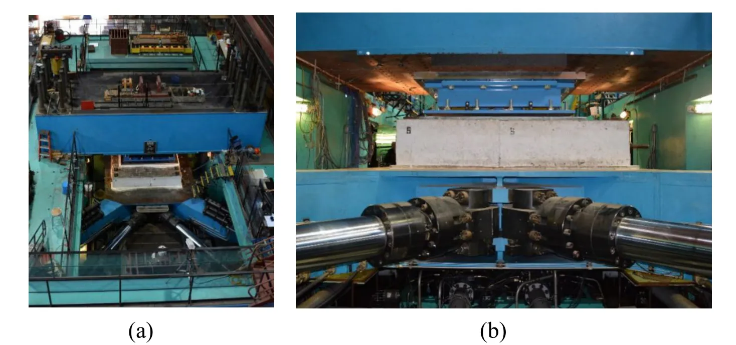
Figure 1:SRMD testing facility:(a) overview and (b) installed bearing

Table 1:SRMD machine technical specifications [Shorteed,Seible,Filiatraut et al.(2001)]
3 Hybrid simulation using SRMD
While the SRMD was not originally designed with the intent of conducting hybrid simulations,it includes different software and hardware components that allow for this adaptation.Hybrid simulation requires that customizable hardware components communicate between the computational driver,which solves the equations of motion for the hybrid model and the controller in the laboratory loading the experimental subassembly.For the large scale bearing tests presented here,the hybrid model communicates with the SRMD control system in each integration time step to send command signals and receive measured feedback signals.For real-time testing,communication needs to be fast and reliable among the various components.Performance limitations such as actuator tracking,actuator delays,and communication speeds determine the rate of testing that can be achieved.While the implementation presented here is for the SRMD,the challenges discussed can be faced by researchers attempting real-time hybrid simulations of large scale structures under multiple components of excitation.The tests reported are unique in terms of the scale of the structures examined,the multiple components of loads and displacements applied on the experimental subassembly,and the large number of DOF in the numerical models.
3.1 Software configuration
The complex models utilized in the hybrid simulation presented here require integrated software components and fast computational solvers that communicate continuously with the experiment throughout the test in order to run a smooth hybrid simulation.The key software components as implemented at the SRMD facility for this test series are described below.Several improvements and additions that were specifically developed for this project include the deployment of multi-processor computational driver software and updated OpenFresco middleware software.
3.1.1 OpenSees and OpenSeesSP
The use of OpenSees as the computational driver in hybrid simulation provides advanced capabilities for modeling and analyzing the nonlinear response of structural systems using a wide range of material models,elements,and solution algorithms.OpenSees is designed for parallel computing (OpenSeesSP) to allow for scalable simulations on highperformance computing platforms [OpenSees (2014)].Using OpenSeesSP in hybrid simulation provides researchers with the ability to expand to more complex nonlinear numerical models with many thousand DOF and execute them at a faster rate.The rate of testing in a hybrid simulation depends on the computational time of the numerical model and the achievable rate of loading of the testing facility.
The deployment of the MUMPS (MUltifrontal Massively Parallel sparse direct Solver) [Amestoy,Duff,L’Excellet et al.(2001)] solver in OpenSeesSP significantly increased the speed of solving the system of equations of the hybrid model considered in this research.When running an analysis on a parallel machine with n processors,a single processor (P0) is running the main interpreter and processing commands from the main input script while the other processors are running Subdomain objects [McKenna (1997)].On the first execution of theanalyze() command,the model is partitioned,that is,the elements are split and distributed among n-1 processors to solve the system of equations in parallel [McKenna and Fenves (2007)].Computational models in this testing program utilized the MUMPS parallel solver in OpenSeesSP to rapidly solve the large system of equations.For hybrid simulation,in order to maintain communication with the real-time DSP in the experimental facility,experimental element related computations must remain on the main processor (P0).This can be achieved by calling a recently developed partition function and setting the partition for the experimental element to P0 (main processor) [partition $eleTag] before the first call of theanalyze() command.The middleware,discussed next,makes this software readily adaptable for hybrid simulation.
3.1.2 OpenFresco
The OpenFresco (Open-source Framework for Experimental Setup and Control) software framework is a middleware used to connect a finite element model with experimental hardware,in this case the SRMD control and data acquisition systems [OpenFresco (2014)].A new experimental bearing element was developed and programmed in OpenFresco that is able to transfer three translational and three rotational DOF to the experimental substructure.In addition,this new experimental bearing element provides the userselectable option to either transfer axial deformation or axial force to the test specimen.Due to the high axial stiffness of the bearings being tested,force control is more reliable in the vertical direction.This enables 3D testing that can capture the coupled verticalhorizontal behavior of large-scale seismic isolation bearings with variability in axial force due to overturning moment and vertical ground excitation.Furthermore,a new option was added to the experimental control objects,including the SCRAMNet+ (Shared Common Random Access Memory Network) experimental control used in this study,to utilize either absolute (default) or relative trial displacements.
3.1.3 Real-time predictor-corrector
The SRMD control system operates at a rate of 1000 Hz,updating the actuator commands and getting feedback signals from sensors measuring the current displacement and force state of the platen.For smooth control and movement of the platen,the commands to the actuators from the hybrid model should be updated at an identical rate.However,the numerical portion of the hybrid simulation is often times not running in a real-time environment and could thus require variable calculation times that randomly exceed the allowed time (a fraction of the integration time step size) to calculate new target values for the control system.Therefore,a real-time predictor-corrector algorithm is deployed to generate smooth command signals updated at the same rate as the control system base clock frequency while receiving displacement targets from the numerical model at a nondeterministic rate.
The predictor-corrector algorithm [Mosqueda,Stojadinovic and Mahin (2005);Schellenberg,Mahin and Fenves (2009)],was programmed in Simulink and Stateflow within the MATLAB environment as shown in Fig.2 [Mathworks (2013)] and then downloaded to run on the xPCTarget in real time.A polynomial is fitted to the displacement targets received from the hybrid model to generate a continuous command signal at the desired rate.The order of the fitted Lagrange polynomial can simply be changed in the state-flow coder diagram (see Fig.3) before executing a hybrid test.For these simulations,second order polynomials were selected for displacements,velocities and accelerations.To synchronize the nondeterministic execution of the OpenSeesSP/OpenFresco analysis with the determinist execution of the control system,the predictor-corrector algorithm performs the following tasks:1) while the analysis software solves the equations of motion for the new target displacement,the pcalgorithm generates command displacements based on polynomial forward prediction;2) once the new target displacement has been received,the pc-algorithm switches into the correction mode where it generates command displacements driving the platen response towards the new target displacement;3) if the new target displacement is not received within 60% of the simulation time step size,which was set at 10 msec,the pc-algorithm gradually slows down the command displacements until the new target displacement is received.Therefore,in order to achieve a real-time execution of the hybrid test without any slowdowns,the OpenSeesSP analysis software needs to compute a new target displacement in less than 0.6×10=6 msec.To reduce communication delays between OpenFresco and the pc-algorithm,the execution of the predictor-corrector finite state machine as shown in Fig.2 was upsampled by a factor of 10.This means that the prediction-correction tasks and the polling of OpenFresco communication flags are performed at a frequency of 10 kHz instead of 1 kHz which enables a smoother and faster operation of the synchronization performed by the pc-algorithm.Predictor-corrector states were monitored and recorded for all hybrid tests at the simulation time step interval of 10 msec.No slowdowns were encountered and on average the pc-algorithm performed 3 msec of prediction and 7 msec of correction,hence,real-time execution was achieved.
3.2 Hardware configuration
In general,a hybrid simulation requires a computational driver to solve the equations of motion of the hybrid model using time integration algorithms.Continuous communication of commands and feedback with the SRMD controller was achieved using the architecture shown in Fig.3.The architecture includes a computational driver,the SRMD control system and a real-time digital signal processor communicating through SCRAMNet+.The SRMD controller is used in a manner similar to conventional cyclic dynamic testing except that instead of providing a predefined loading signal,the longitudinal and lateral displacement commands and the vertical force command are external reference signals being computed by the numerical model as the simulation progresses.In its original configuration,the SRMD control system could only receive and send signals through analog input/output channels and this was the approach used in previous tests [Schellenberg,Sarebanha,Schoettler et al.(2015)].To enable real-time testing and eliminate previously encountered problems with synchronization,delays,and noise caused by D/A and A/D conversions,the SRMD control system was upgraded with a SCRAMNet+ interface that provides complete digital communication,thus eliminating intermediary D/A and A/D conversions.The different components of this hybrid simulation system are discussed in the following sections.
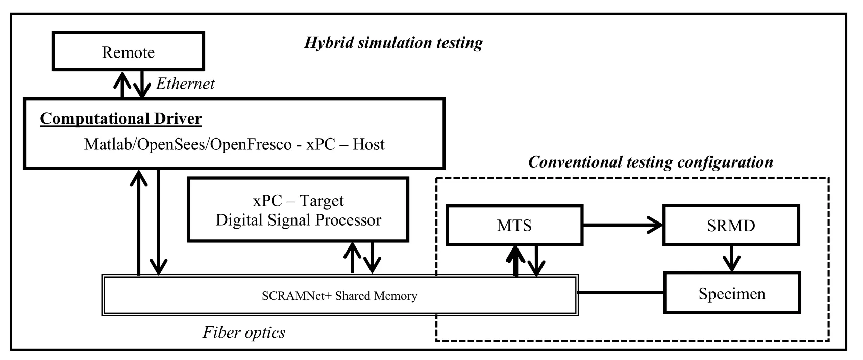
Figure 3:Hybrid simulation hardware configuration
3.2.1 Digital signal processor for real-time signal generation
To generate the real-time signals for the SRMD control system,Simulink Real-Time [Mathworks (2013)] was used.In this high performance host-target prototyping environment,the host computer runs the numerical analysis model while the target computer runs a real-time kernel essentially converting a regular PC into a digital signal processor (DSP) that operates in real-time.During a hybrid simulation,the digital control signals generated by the predictor-corrector algorithm running on xPC-Target are written into pre-allocated memory locations on the SCRAMNet+ memory ring and are almost instantaneously made available for the SRMD control system to process.Any memory changes made by any one computer on the network are replicated on all the other computers on the network within nanoseconds [SCRAMNET+ (2000)].A memory map has been predefined to allocate reserved memory partitions on the SCRAMNet+ for reading and writing of data from the xPC and SRMD controller nodes.
3.2.2 Control system of the SRMD
The SRMD applies loads through a platen system governed by movements of its collective actuators.The digital real-time controller provides closed-loop,6-DOF control of system motion including vertical,lateral,and longitudinal translations,and yaw,pitch,and roll rotations.This facility was primarily designed to apply large displacements at relatively high velocity as well as high axial load on seismic isolation devices.Each actuator is controlled using a multi-stage closed-loop control system,where the inner loop controls the poppet valves for flow of oil into the actuators and the outer loop controls actuator displacements.Four-stage poppet valve assemblies are used in place of the more common multi-stage servo valves typically employed in structural testing.These valves are able to achieve the high volume of oil flow needed to facilitate the fast movement of these actuators,at the expense of less control accuracy.This can be of particular concern for hybrid simulation because displacement control errors can propagate through the numerical model and potentially lead to instability.However,careful control and compensation of these errors can produce reliable simulation results as will be demonstrated here.
3.3 Communication between hybrid simulation components
As described in the previous section,several hardware and software components as well as correction and compensation procedures are necessary to conduct hybrid simulations with the SRMD.Fig.4 shows the different components and their line of communication with each other.The numerical model is programmed in OpenSeesSP to solve the governing equations of motion at each integration time step for the hybrid model.OpenSeesSP calculates new target displacement values for the next time step and sends these to all numerical elements as well as the experimental element in OpenFresco,which generates the desired deformations and loads on the isolator test specimen.OpenFresco transforms the target signals from global DOF to basic element DOF and then communicates with the xPC-Target machine running the Simulink predictor-corrector model.As described above,this Simulink model running in real time is able to generate smooth command signals by writing digital signals to SCRAMNet+ memory each 1 msec using a predictor-corrector algorithm within the simulation time step.Next,the SRMD real-time controller reads these command signals as external reference signals and commands the motion of the table platen accordingly.
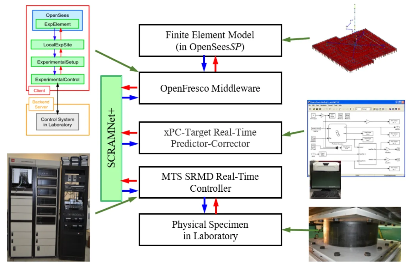
Figure 4:Schematic of the test setup
At the end of each simulation time step when the target displacement is reached by the SRMD,force and displacement measurements of each desired DOF are obtained and then sent back to the numerical model.These response quantities are also referred to as feedback signals.For a 2D hybrid simulation,the measurements are two horizontal displacements and their corresponding horizontal shear forces.These feedback forces not only consist of internal forces in the physical seismic isolation bearing but also include inertia and friction forces of the platen.A shear force observer was implemented by measuring platen horizontal DOF forces through the actuator uniaxial load cells and subtracting inertia and friction forces before sending them back to the hybrid model.The feedback force correction was implemented within the Simulink real-time model.Once the numerical simulation receives the restoring forces from both the numerical and experimental elements,the system response is solved and the analysis proceeds to the next integration time step.For a 3D hybrid simulation,the measurements also include the vertical displacement and force of the bearing.Considering that the bearing has high vertical stiffness and that the vertical displacement range of the bearing is relatively small compared to the accuracy of the SRMD facility in the vertical direction,a small displacement error will amplify to a large force feedback error.Therefore,the vertical DOF is operated in force control with the force predicted by the numerical model as has been done in previous hybrid simulations [Pan,Nakashima and Tomofuji (2005);Del Carpio,Mosqueda and Hashemi (2015)].A multilinear elastic model with viscous damping fitted to results from vertical characterization tests is used to simulate the bearing behavior in axial direction.In this approach,the vertical force measurement in the 3D tests is not sent back to the hybrid model.Instead,the vertical bearing force estimate by the spring model is used and this force value is also the vertical force command sent to the SRMD to apply varying axial load on the experimental bearing.
3.4 Preparation for hybrid test
Before executing a hybrid simulation,preliminary checks can ensure that different components are communicating properly including feedback signals sent to the numerical model.As shown in Fig.5,the Simulink block on the top left reads the command signals (longitudinal and lateral displacements and vertical force) from OpenFresco and the block on the bottom left reads the feedback signals (displacements,accelerations,and forces of the platen) from the SRMD control system.Similarly,the block on the top right writes reference commands (longitudinal and lateral displacements and vertical force) to the SRMD controller and the block on the bottom right writes feedback signals (isolator shear forces) to OpenFresco.Pretest simulations were conducted first with feedback simulated by a numerical model and compared to the actual feedback to ensure proper communication.
3.4.1 Delay compensation
Delay is an important characteristic of the experimental loading system that needs proper compensation in real-time hybrid simulation.In general,delay is the time difference between the command signal and its measured response.The rate of testing in hybrid simulation is primarily governed by the computation time of the numerical model,communication times,and the delay in the actuator system.For these tests,the numerical portion of the response was computed using a custom-built high performance computer with parallel processing capabilities achieving computation times that were sufficiently fast to enable real-time testing.Communication times were minimized through the use of SCRAMNet+ shared memory.
In order to assess system delays in the SRMD for the different platen DOF,cross correlation functions and minimization of RMS (root mean square) errors between measured and commanded signals were used for system identification.The maximum of the cross correlation between these signals indicates the time delay that these two signals are best aligned [Bendat and Piersol (1993)].In the latter method,system delay corresponds to the required time shift in the measured signal where the RMS of the difference between measured and commanded signal is minimum.
The SRMD was estimated to have about 60 msec of delay in the measured displacement response compared to a command from its internal function generator.This delay is mainly due to a lag in the response of the hydraulic actuators driven by the four-stage poppet valve assembly.To minimize delays and enable real-time testing,more advanced control strategies and delay compensation techniques were adopted.
3.4.2 Feedforward gain
One approach to reduce delay in the test setup is to use advanced control strategies available within the SRMD control system,such as feed-forward (FF) control.In the feed-forward control strategy,the time derivative of the command signal is multiplied by the feedforward gain,and added directly to the valve command signal.Basically,the command signal predicts the next value by using the current velocity,which can be problematic,especially for higher frequency signals where FF control tends to overshoot.Tuning the system for feed-forward gain provided a significant tracking improvement in the two horizontal directions,however,it could not fully compensate for the total delay.FF control was not effective in vertical direction because the control system is based on a cascade control loop where the inner loop is in displacement control and the outer loop is in force control.
3.4.3 Adaptive time series compensator
The adaptive time series (ATS) compensator developed by Chae et al.[Chae,Kazembidokhti and Ricles (2013)] was used to further minimize the delays in the SRMD response.This adaptive delay compensation method predicts a time-advanced command signal to compensate for delay.It uses three adaptive gains (a0,a1,and a2) which scale displacement,velocity and acceleration based compensators.These gains are continuously updated at the control system frequency using the least squares method to minimize control errors.To apply the ATS compensator to the SRMD,two minor modifications were made.First,the algorithm was extended to perform adaptive delay compensation individually for each DOF of the SRMD.Second,the ATS was modified to utilize reference velocities and accelerations directly from the predictor-corrector algorithm instead of computing them by differentiating reference measured displacements.Since the predictor-corrector algorithm utilizes polynomials for extrapolation and interpolation,it was possible to directly differentiate the Lagrange polynomials for displacement to obtain velocity and acceleration polynomials.This modification produced more accurate velocity and acceleration references with significantly reduced noise than the original implementation.
A Simulink block of the ATS originally developed by Chae et al.[Chae,Kazembidokhti and Ricles (2013)] was added into theHybrid ControllerSimulink model and adaptive gain margins were calibrated prior to performing a real-time hybrid simulation to ensure stability and proper delay compensation (see Fig.6).After its implementation,it was found that the ATS compensator combined with FF gain control were able to reduce the average delay in the SRMD from 60 msec down to about 5 msec,making real-time testing feasible.The ATS compensator was originally developed and validated for systems using
displacement control;while the vertical DOF of the SRMD is usually controlled in force.It was found that the ATS was not as effective in compensating for delay in the bearing axial DOF during real-time hybrid tests.This was likely due to the higher frequency content in these signals.However,use of the ATS compensator in slower hybrid simulations resulted in better tracking of axial forces in vertical direction.
Fig.7 shows the adaptive change of the gains (a0,a1,and a2) for the longitudinal DOF for one of the real-time hybrid simulations.The a0-gain compensates for over or under shoot.As can be seen from the figure,the gain tended to be less than one over large portions of the hybrid simulation,meaning that there was more compensation necessary for overshoot than undershoot.This is due to the feed-forward control that tends to create overshoot as was described earlier.The a1-gain corresponds to the delay compensation.As can be seen from the figure the ATS adaptively compensated for delays between 0 and 60 msec over the course of the hybrid simulation.The a2-gain is the higher order term and a function of the delay compensation square.All these three gains reach their limits only in a few instances for the example shown.
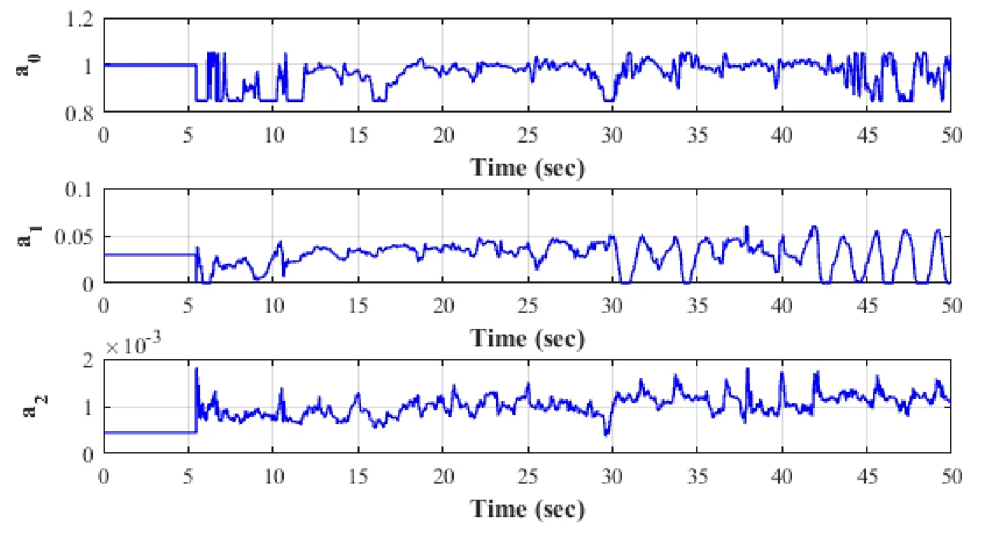
Figure 7:Adaptive change of ATS compensator gains during a hybrid simulation
3.4.4 Rate of testing
After testing different combinations and settings of delay compensation methods for this test setup,employing a combination of FF control and ATS delay compensation showed to be the most effective method to eliminate delays in both longitudinal and lateral direction and enabled real-time hybrid testing for 1D and 2D excitation (controlling one or two horizontal displacements).However,3D hybrid tests (controlling the vertical force on the bearing as well as horizontal displacements) could not be carried out in real time because delay compensation techniques were not able to sufficiently improve tracking performance for the high frequency vertical forces to guarantee both stability and accuracy.
3.5 Correction of feedback forces for inertia and friction force
Feedback forces in the SRMD were obtained from uniaxial load cells on the actuators.The horizontal force measurements include the resisting forces in the seismic isolation bearing plus inertia and friction forces of the SRMD platen.Prior to sending these feedback signals as restoring forces to the hybrid model,corrections were required to remove inertia and friction forces from the measured signals.While a load cell right beneath the bearing could directly measure the actual shear force in the bearing as is done in most small scale test setups,this would be difficult and costly considering the magnitudes and multiple components of the forces that need to be measured as part of this testing program.A shear force observer was needed to correct for friction and inertia on the fly.In standard cyclic characterization testing of devices on the SRMD,these effects are corrected during posttest analysis.Most often the correction is performed by subtracting the measured forces from an empty table run of the same input motion.While an empty table run should ideally provide zero shear force readings in the absence of friction and inertia,large forces on the order of 2,000 kN have been observed during fast tests with significant accelerations.This is mainly due to inertia forces of the platen mass and friction due to the platen sliding on the vertical actuators and outrigger supports.
Ozcelik et al.[Ozcelik,Luco,Conte et al.(2008)] studied and verified the applicability of parameter identification approaches to model the mechanical subsystem of the Large High Performance Outdoor Shake Table at UC San Diego.Using a similar approach,a model for correction of inertia and friction forces for the SRMD was developed and calibrated using system identification techniques.
In this model,inertia forces due to the table platen were calculated based on the calibrated effective mass of the setup consisting of specimen,platen,and moving actuator parts in each of the three translational DOF,and the measured accelerations in each direction.Accelerations were measured with accelerometers placed on the table platen.The effective mass of the table changed for different setups based on required spacer blocks and the moving mass of the bearing test specimen.For the friction force,previous studies of the SRMD have identified the dependence of the friction force on velocity as well as the direction of sliding [Shortreed,Seible,Filiatraut et al.(2001)].Previous studies also indicated that the longitudinal and lateral directions have different static friction values and different velocity dependent friction values.It was assumed that friction forces consisted of a combination of static and dynamic components.Static friction is a constant friction value that changes sign based on the direction of sliding.The dynamic portion of the friction force is assumed to be linearly proportional to the velocity of sliding (sliding velocity exponent α=1).
The model was developed based on runs with an empty table platen in which the measured forces (Fmeasured) are recorded using actuator load cells and horizontal accelerations (ü) are recorded using accelerometers on the table platen.Feedback velocity () was calculated from measured displacements using actuator displacement transducers.The unknown parameters are effective mass (me),static friction force (FStatic_Friction),dynamic friction force (FDynamic_Friction) and any offset (d) in the force measurements.With these assumptions,the following equilibrium equation (Eq.(1)) was derived for horizontal forces in both longitudinal and lateral direction for an empty table run.

Results from several empty table runs (both harmonic and earthquake excitation) were used to calculate the unknown parameters for the proposed model.Using system identification techniques,a linear least squares model with linear constraint was fitted for the given data sets independently for both longitudinal and lateral direction to calculate the unknown model parameters.It should be noted here that assuming a nonlinear dependency on sliding velocity for the dynamic friction component did not significantly improve the estimation of friction forces in the system (i.e.,sliding velocity exponent 0.1<α<2).Also,the experimental setup used for testing of different types of bearings was different therefore effective masses for these setups were different while the friction behavior was assumed to remain the same.Tab.2 shows the calculated parameters for the inertia and friction force correction model.

Table 2:Parameters calculated for resisting force correction
Once inertia and friction parameters were calculated,the force correction model was implemented into theHybrid ControllerSimulink model.In this model,longitudinal and lateral velocities are calculated based on feedback displacements (instead of commanded displacements) of the platen to ensure that they are in phase with the actual motion of the platen.Readings from accelerometers located on the table platen were also used for the inertia force correction.To make sure that force corrections were applied with the proper phase,some empty table runs were first examined producing velocities in the range that was expected for the hybrid tests.
To avoid rapid changes in the force feedback,especially at displacement reversals when the velocity can fluctuate in sign due to noise,the friction force was set to zero below a threshold velocity (0.05 in/sec).This threshold value also helped with free vibration at the end of the experiment when the velocity oscillates and large changes in the friction force would cause high frequency noise in the measured signals sent back to the hybrid model.The force correction model,schematically shown in Fig.8,was calibrated by minimizing the measured force to zero during empty table runs.
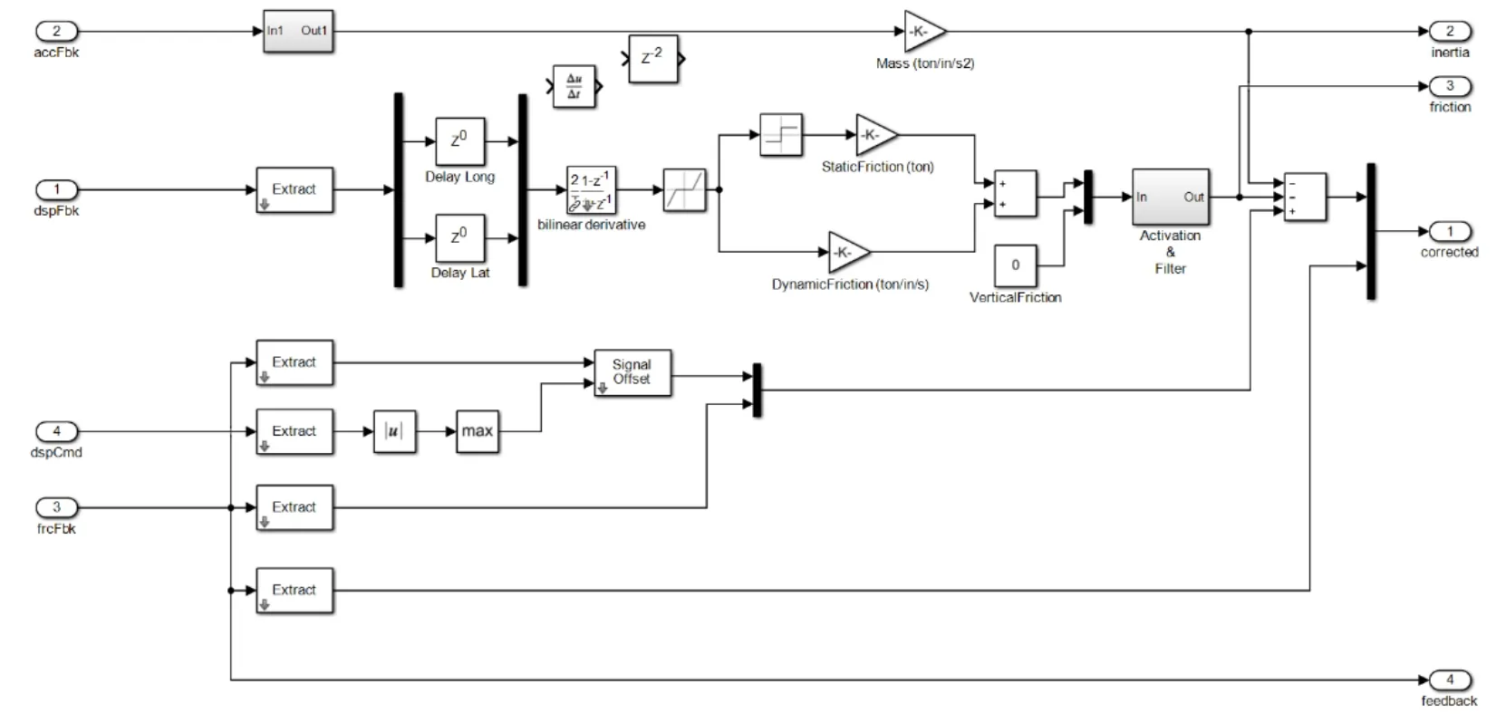
Figure 8:Model schematic to correct for friction,inertia and offset
Based on a study by Shortreed et al.[Shortreed,Seible,Filiatraut et al.(2001)],there is one additional source of friction in the SRMD that depends on the vertical load.Movement of the platen will involve nine different friction surfaces,eight on the outrigger actuators and one on the four vertical actuators beneath the table platen,see Fig.9.This vertical load dependent friction force is a function of the direction of motion,outrigger forces,vertical load and lift pressure.Based on the expected vertical load on the bearing during the hybrid simulations,constant friction values can be calculated for different directions.This friction force could be calculated in each time step and updated values could be used for the correction.However,variations of this portion of the friction force were found to be negligible for most tests and were not included.
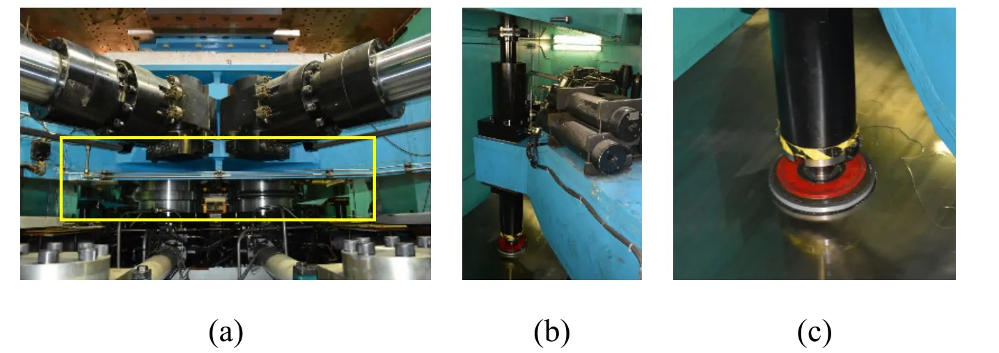
Figure 9:Machine contact surfaces:(a) vertical actuators under platen,(b) top and bottom outrigger supports,and (c) outrigger sliding surface
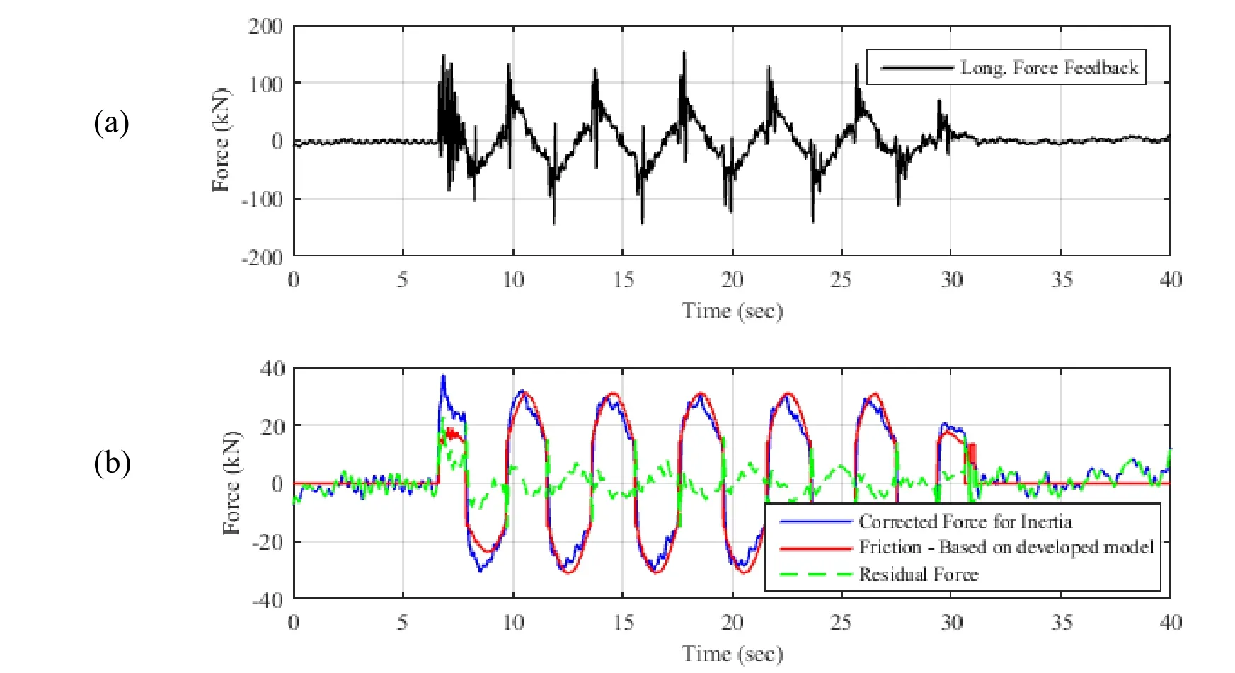
Figure 10:Sample correction of feedback forces (longitudinal direction):(a) raw force feedback,(b) friction forces and residual error between actual and predicted friction
Fig.10 shows an example of a correction procedure to recover the bearing resisting force.Here it is applied for an empty table run without a bearing where there should be ideally zero residual force after correction for inertia and friction.As shown,the residual force is mostly below 10 kN (~0.01% of the longitudinal SRMD force capacity) which is within the expected range of force accuracy.This procedure was applied to instantaneously correct bearing horizontal shear forces during the hybrid simulations.
4 Test setup
Hybrid simulations were conducted for a seismically isolated Archetype Nuclear Test (ANT) power plant model provided by KEPCO E&C.The ANT model represents a simplified version of the Korean Advanced Power Reactor (APR1400) nuclear power plant design with 486 bearings.Three variations of this ANT model were provided and tested in this testing program.The three models consisted of the same plant superstructure but used three different approaches to model the seismic isolation plane considering that only one bearing could be experimentally evaluated in the hybrid simulation.The first and simplest model utilized one equivalent bearing element to represent the entire isolation plane.The second model consisted of 5 bearings where each one of them represented a group of bearings under the four sections of the auxiliary building and the region under the reactor containment building.The third and most complex model included all 486 bearings in the isolation plane.The 1-bearing equivalent model experienced a somewhat different response than the other two hybrid models since the isolator response in this model was entirely determined by the experimental test specimen whereas in the other two models the response of the isolation system was mostly dictated by the numerical isolators.Also,for both the 5-bearing equivalent model and the 486-bearing model the experimental isolator represented a corner location where the isolator is affected by overturning effects.In contrast,for the 1-bearing equivalent model no overturning effects were captured.Details on the three analytical models,numerical bearing element models used for simulating the analytical bearings,and a discussion on how the numerical bearing model parameters were calibrated to be used for the hybrid simulations can be found in Schellenberg et al.[Schellenberg,Sarebanha,Schoettler et al.(2016)].
Three bearing manufacturers provided full-scale test specimens to be used as the physical subassemblies in these hybrid simulations.The three bearing types included a lead plug rubber bearing (LPRB),a friction sliding bearing with a flat sliding surface and compression springs (EQSB),and a triple pendulum friction bearing (TPFB),see Fig.11.The three specimens had significantly different design and ultimate displacement capacities.A summary of their design properties is provided in Tab.3.

Figure 11:(a) LPRB,(b) EQSB,and (c) TPFB bearings used in this testing program

Table 3:Summary of design properties for the seismic isolation bearings
5 Hybrid simulation test results
For brevity,only three test results from LPRB under 2D and 3D design basis earthquake level excitation are presented here.These tests and analyses presented utilized the 1-bearing equivalent ANT model to preclude any influence of the analytical bearing in the hybrid simulation results.Analytical simulations were conducted (using bearing properties calibrated based on characterization test results) with the LeadRubber-X bearing element in OpenSees.Future publications will examine behavior of the bearings in more detail.Results presented here focus on the structural responses recorded by OpenSees and OpenFresco.For each comparison,the behavior of the experimentally tested isolator is presented in terms of displacement and force demands and the in-structure response is presented in terms of floor response spectra.For the isolator specimen,hysteresis loops in longitudinal and lateral directions,the horizontal displacement orbit and the shear force interaction surface are provided.For the plant superstructure,floor response spectra are provided at three different elevations in the reactor containment building (RCB),the internal structure (INS),and the auxiliary complex building (ACB).The response spectra for the input ground motions are also included.The elastic response spectra were generated by analyzing 2 DOF linear-elastic systems with 5% damping and the reported spectral quantities are vector norms of the response quantities in the two horizontal directions.
5.1 Results:2D excitation-real time
Results are first shown for a real-time hybrid simulation with two horizontal components of ground motion excitation at the design hazard level for the considered structural model.Comparisons of the results for the hybrid and pure numerical simulation are given in Fig.12 for the bearing response.The maximum displacement demands from the hybrid test are 190 mm in the longitudinal and 206 mm in the lateral direction,which is smaller than the 233 mm and 308 mm demands from the analysis with bearing models calibrated to initial characterization tests on the same bearings.The comparison of the shear force interaction surfaces shows that typically the shear forces in the hybrid test are larger than in the analytical simulation.The maximum shear force in the hybrid test is 2,322 kN,which is larger than the 2,038 kN shear force from the numerical analysis.
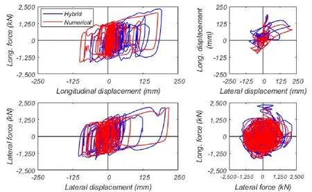
Figure 12:Comparison of hybrid simulation (real time) and purely numerical analysis using a LeadRubber-X bearing element and 2D excitation-Hysteretic response
The in-structure response is compared in Fig.13 with floor response spectra at an elevation of 47.5 m in the reactor containment building,internal structure,and auxiliary building.This figure also contains the analytical response of a fixed base ANT model,which demonstrates the reduction in high frequency spectral accelerations achieved by seismic isolation.It can also be seen that for frequencies above 6 Hz,the response spectra for the RCB,INS,and ACB are consistently greater for the hybrid simulation than the optimized numerical analysis.The spectral peak at 7.6 Hz corresponds to the first- and second-mode frequencies of the ACB.The difference between analytical and experimental results here are mainly due to added high frequency experimental errors.However,results from another test (x2 slower than real time) reported in Sarebanha et al.[Sarebanha,Schellenberg,Schoettler et al.(2018)] shows that when the tracking is improved,floor spectra from the hybrid test results have smaller amplitude than results from analytical models in the 7 to 11 Hz frequency range.This is due to smoothness of the actual measured bearing behavior compared to the behavior of the analytical bearing model.
In contrast,floor spectral accelerations from the hybrid simulation are lower than the numerical simulation at 2.8 Hz.This frequency corresponds to the isolator responding in its linear-elastic range and is more pronounced for the numerical simulations.
The effectiveness of the delay compensation method in terms of average delay and displacement errors between command and measured displacement for this hybrid test are shown in Fig.14.Average delays in the real-time test were 6.3 msec in longitudinal and 3.8 msec in lateral direction and normalized RMS errors were less than 1% during this test.
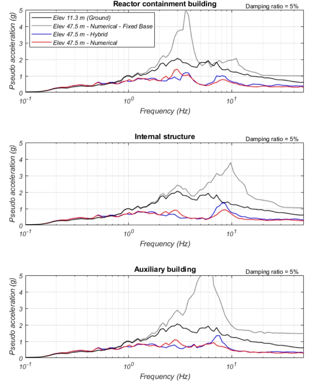
Figure 13:Comparison of hybrid simulation (real time) and purely numerical analysis using a LeadRubber-X bearing element and 2D excitation-In-structure floor response spectra
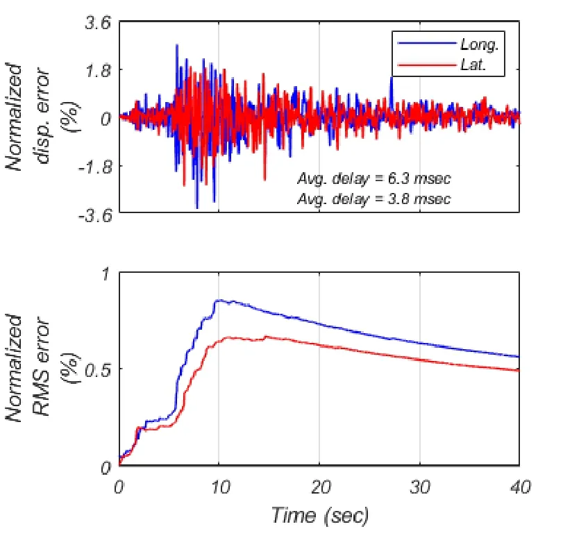
Figure 14:Normalized displacement and RMS errors for hybrid simulation (real time) using a LeadRubber-X bearing element and 2D excitation
5.2 Results:3D excitation-x10 slower than real-time
A hybrid simulation with all three components of the ground motion at the design hazard level was executed at a rate 10-times slower than real time due to limitations in the vertical control.The bearing response is compared to the corresponding numerical simulation in Fig.15.It can be seen that the maximum shear force from the hybrid simulation test is close to the optimized analysis results while shear-force fluctuations in the hybrid test are more pronounced than in the pure numerical results.
The in-structure response is compared in Fig.16 with floor response spectra at an elevation of 47.5 m.As shown,the analytical model lacks the ability to accurately capture the vertical-horizontal coupling behavior of the bearing which leads to an underestimation of spectral accelerations at higher frequencies (between 7 to 11 Hz).The spectral peaks in the hybrid test results occur at a frequency of ~8.5 Hz,which is very close to the fundamental vertical frequency of the plant superstructure at about 10 Hz.Note that these observation are not expected to be due to experimental errors as reported earlier since slower tests typically did not show the amplification show in Fig.13.Comparing the response of the fixed base and isolated structure,significant reduction in spectral acceleration was achieved by seismic isolation for frequencies above 0.6 Hz.
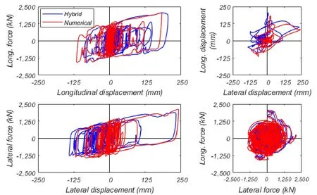
Figure 15:Comparison of hybrid simulation (x10 slower) and purely numerical analysis using a LeadRubber-X bearing element and 3D excitation-hysteretic response
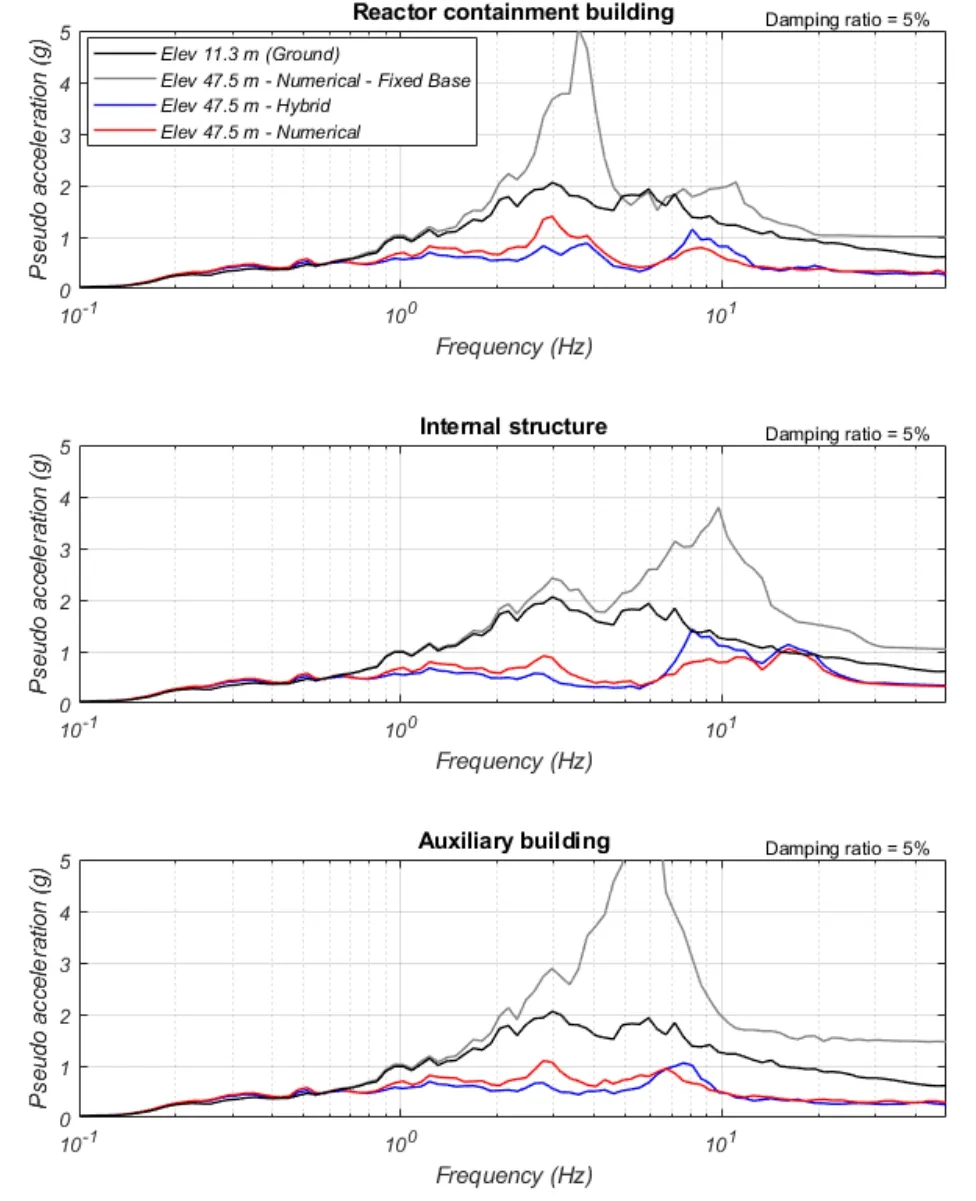
Figure 16:Comparison of hybrid simulation (x10 slower) and purely numerical analysis using a LeadRubber-X bearing element and 3D excitation-in-structure floor response spectra
6 Conclusions
This research program confirms that real-time hybrid simulation is a viable testing method to experimentally assess the behavior of large isolators at full-scale.It was demonstrated that a high-performance computing platform with parallel processing capabilities (OpenSeesSP) can be used to perform real-time hybrid simulations of large structures with many thousand DOFs.As part of this project,a new partitioning capability was implemented in OpenSeesSPto keep the experimental element(s) on the main processor (P0) to maintain communication between analysis solver and the real-time DSP throughout the tests.
The SRMD bearing test machine was successfully converted to perform fast and real-time hybrid simulation tests for very large numerical models.A fast digital communication network between different hardware components of the hybrid test system was successfully implemented in an effort to enable real-time hybrid simulation at the SRMD testing facility.During the experimental test program,the tracking performance (in terms of delays) was significantly improved by employing a combination of the Adaptive Time Series delay compensator and using feedforward-control in the actuator control system.Employing these advanced delay compensation techniques enabled real-time or near real-time hybrid testing for 1D and 2D excitations (controlling one or two horizontal displacement DOF).It was determined that 3D real-time hybrid simulations with the SRMD is not feasible due to insufficient vertical tracking performance.To achieve acceptable performance and accuracy in the force controlled vertical DOF,a hybrid simulation should be performed at a minimum 10x-slower than real time.
Despite the lack of a load cell to directly measure the experimental bearing forces,reliable test results were obtained by measuring forces from actuator load cells and correcting them instantaneously for friction and inertia force effects in the test setup.To this end,a new model for inertia and friction force correction was developed,implemented and then calibrated for different test setups using system identification techniques.
It is recommended to further improve the tracking performance of the SRMD machine for any future hybrid simulations performed on this testing system.Because it is apparent that real-time or near-real-time hybrid simulations of seismic isolation systems can more closely capture the true behavior of the isolators,it is recommended that strategies be developed to further minimize tracking errors and improve control in horizontal and more importantly vertical direction.
Acknowledgments:This research was supported from KEPCO Engineering and Construction Company,Inc.The authors are grateful for this financial support.The authors are grateful for the assistance of various experts on earthquake engineering including Professor James Kelly and Dr.Frank McKenna.The success of this project was due in large part due to the skill and efforts of staff at the Structural Response Modification Device Laboratory at UC San Diego.The authors are appreciative of the advice and technical support provided by the engineering staff of the KEPCO Engineering and Construction Company,Inc.,especially Mr.Jae-Hee Kim,Dr.Seung-Ryong Han,Dr.Ilhwan Moon,and Dr.Sang-Hoon Lee.Testing was facilitated by the presence of knowledgeable engineers from Unison eTech,ESCO RTS,and Earthquake Protection Systems.A significant gain in hybrid testing performance was achieved thanks to the assistance of Brad Thoen from MTS Systems Corp.
Any opinions,findings,and conclusions or recommendations expressed in this report are those of the authors and do not necessarily reflect those of KEPCO Engineering and Construction,the Pacific Earthquake Engineering Research Center,or the Regents of the University of California.
 Computer Modeling In Engineering&Sciences2019年9期
- Computer Modeling In Engineering&Sciences的其它文章
- Coupling of Peridynamics and Numerical Substructure Method for Modeling Structures with Local Discontinuities
- Fragility Assessment of Pre-Northridge Steel Moment Frames Using Finite-Length Plastic Hinge Elements and Concentrated Plasticity Fracture Elements
- The Behavior of Rectangular and Circular Reinforced Concrete Columns Under Biaxial Multiple Excitation
- Structural Finite Element Software Coupling Using Adapter Elements
- Experiment and Simulation for Controlling Propagation Direction of Hydrofracture By Multi-Boreholes Hydraulic Fracturing
- Determination of Working Pressure for Airport Runway Rubber Mark Cleaning Vehicle Based on Numeric Simulation
