Coupling of Peridynamics and Numerical Substructure Method for Modeling Structures with Local Discontinuities
Baoyin Sun ,Shaofan Li,Quan Gu , and Jinping Ou
Abstract: Peridynamics (PD) is a widely used theory to simulate discontinuities,but its application in real-world structural problems is somewhat limited due to the relatively low-efficiency.The numerical substructure method (NSM) presented by the authors and co-workers provides an efficient approach for modeling structures with local nonlinearities,which is usually restricted in problems of continuum mechanics.In this paper,an approach is presented to couple the PD theory with the NSM for modeling structures with local discontinuities,taking advantage of the powerful capability of the PD for discontinuities simulation and high computational efficiency of the NSM.The structure is simulated using liner elastic finite element (FE) model while the local cracking regions are isolated and simulated using a PD substructure model.A force corrector calculated from the PD model is applied on the FE model to consider the effect of discontinuities.The PD is integrated in the substructure model using interface elements with embedded PD nodes.The equations of motions of both the NSM system and the PD substructure are solved using the central difference method.Three examples of two-dimensional (2D) concrete cantilever beams under the concentrated force are investigated to verify the proposed coupling approach.
Keywords: Peridynamic,numerical substructure method,local discontinuities,crack.
1 Introduction
Fracture plays an essential role in the analysis of brittle structures,e.g.,concrete structures.However,it remains a challenge task in computational mechanics for simulations of the sudden discontinuities.Finite element method (FEM) based on continuum mechanics has a limitation in modeling the fracture,due to that displacement field is not continuous across the crack surface and derivatives are not available.In order to remedy the shortcoming,various ‘enhanced’ FE methods (e.g.,molecular dynamics [Ravelo and Holian (1995)],extended FEM [Cox (2009);Mohammadi (2008)],virtual crack closure technique [Leski (2007)],discontinuous FEM [Belytschko,Moës,Usui et al.(2001)],etc.) have been proposed to solve the discontinuous problems.Peridynamics (PD) is one of the most widely used methods for simulating the discontinuities [Silling (2000,2003);Silling and Askari (2004,2005);Silling and Bobaru (2005)].In the PD theory,the mathematical description of continuum mechanics is in the forms of integral equations rather than partial differential equations.Therefore,the spatial partial derivatives are not required,and the PD theory is able to simulate discontinuity behaviors,e.g.,cracks.In the PD theory,the integral region is discretized into a collection of particles,and each particle only interacts with other ones in a fixed-radius neighborhood.There are two types of PD models available,i.e.,bond-based PD and state-based PD models.The widely used bond-based PD model is capable of modeling three-dimensional (3D),twodimensional (2D) plane-stress and 2D plane-strain problems but with a fixed Poisson’s ratio of 1/4,1/3 and 1/4,respectively [Gerstle,Sau and Silling (2005,2007)].In order to circumvent the limitation of the fixed Poisson’s ratio,Gerstle et al.[Gerstle,Sau and Silling (2007)] proposed a micropolar peridynamic model,in which a Poisson’s ratio range from -1 to 0.5 is specified to compute the pairwise force and moments between particles.On the other hand,the state-based PD theory calculates the material strain at one particle based on the displacements of all particles within its neighborhood.A constitutive model from conventional continuum solid mechanics can be adopted to calculate the stresses of each particle [Silling,Epton,Weckner et al.(2007)].A large amount of research based on the state-based PD theory has been conducted in the past decade [Foster,Silling and Chen (2010);Foster,Silling and Chen (2011);Littlewood (2010);Warren,Silling,Askari et al.(2009)].
Although PD theory could well simulate the fracture behaviors or other discontinuities,it remains a difficult task to analyze the real-world practical engineering problems due to the prohibitive computational cost.Macek,Silling and their co-workers [Agwai,Guven and Madenci (2009);Lall,Shantaram and Panchagade (2010);Liu and Hong (2012);Lubineau,Azdoud,Han et al.(2012);Macek and Silling (2007);Madenci and Oterkus (2014a)] proposed an approach coupling of PD model and FEM,which is able to reduce the computational cost significantly.However,in the conventional PD and FEM coupling method,the local crack or fracture region needs to be pre-determined and the PD model is simulated during the whole process of analysis.Since that in the practical engineering,the location and area of crack region are unknown,in addition,the displacement field of the region may be still continuous before the crack occurs,and therefore,it is not necessary to use the PD model during the entire analysis process.In order to overcome these drawbacks of the FEM/PD coupling approach,this paper proposes a novel coupling approach based on an isolated substructure method [Sun,Gu,Zhang et al.(2017)],in which the global structural response is simulated using an elastic coarse-mesh FE model,named as the master model,while the local discontinuous region will be isolated and simulated using the PD substructure model.The Master model keeps unchanged during analysis,and the PD substructure models are created whenever new cracked regions occur.Therefore,there is no need to know the local discontinuous region in advance.
The proposed approach has several advantages compared with the conventional FEM/PD coupling approach:(1) The location and area of the local cracked region do not need to be pre-determined;(2) The PD substructure system is only performed when the master structure detects the cracking behavior of this region;(3) Various PD substructures are not dependent on each other and they can be computed in parallel;(4) The master structure system and the PD substructure systems can be simulated using the most convenient software platforms taking advantage of their powerful capacities of computation.
This paper is organized as follows.Section 2 briefly summaries the bond-based PD theory and NSM,and the coupling of the PD and NSM;Section 3 introduces the central difference methods adopted to solve the PD model and NSM and the integration technique of PD and NSM;Section 4 gives three application examples of 2D concrete cantilever beam with pre-crack and subject to concentrated end force to verify the coupling approach.
2 Coupling of peridynamic (PD) and numerical substructure method (NSM)
2.1 Bond-based peridynamic theory
In the conventional continuum mechanics,the equation of motion is satisfied at any material point.However,bond-based PD theory computes the material point force by integrating the forces exerted by all surrounding points within the horizonδ.The equation of motion of the particle xiin reference configuration as shown in Fig.1 can be written as,

wheretrepresents the time,denotes the acceleration of particle xi,b is the body force of the particle xi,ρindicates the material density,is the neighborhood of particle xi,f represents the pairwise force vector that particle xjexerts on particle xi,ξ = xj-xiindicates the relative position vector between the particles xiand xjat the reference configurationdenotes the relative displacement vector at the current configuration.
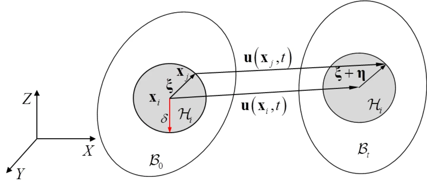
Figure 1:Schematic of PD in reference and current configurations
The pairwise force introduced in Huang et al.[Huang,Lu and Qiao (2015)] can be defined as,

wheresdenotes the bond stretch,given as,andis the micromodulus function indicating the stiffness of a pairwise bond,and kernel functiondescribes the spatial distribution of the intensity of long-range forces in the material [Huang,Lu and Qiao (2015)].The micromodulusc( 0,δ) is obtained based on the consistency between the strain energy densities using the PD theory and classical continuum theory,respectively.Parameteris a factor reflecting the breakage of bond between the particles xiand xj,

in whichs0indicates the critical stretch for bond failure,which can be computed by setting the work required to break all the bonds per unit volume identical to the energy release rateGf[Silling and Askari (2005)].
A damage or failure degree for the PD material at particle xican be defined by using the ratio of amount of broken bonds to the total bonds [Silling and Askari (2005)],

In the PD theory,the integral volume of the particles x and xˆ near the surface (see Fig.2),referred asV(x) andV(),are smaller than that of the inside particle with full spherein 3D andV0=πδ2in 2D).If the bond micromodulus near the surface is taken as that inside the material and,therefore,the strain energy density near the surface is smaller than that inside the material,resulting in a “softening effect” near the surface (named as surface effect herein).
It is reasonable that the strain energy density in each particle should be the same,thus,the computed bond micromodulus value near the surface should be larger than that inside the material.
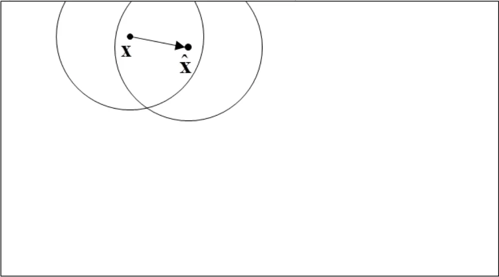
Figure 2:PD particles near the surface
In order to counteract the surface effect,several methods,such as the volume method [Bobaru,Foster,Geubelle et al.(2016);Le and Bobaru (2018)],the force density method [Le and Bobaru (2018);Madenci and Oterkus (2014a,2014b);Oterkus (2010)],the energy method and the force normalization method [Le and Bobaru (2018);Macek and Silling (2007)],have been proposed in the past few years.In this paper,the energy method is adopted to account for the surface effect,in which a multiplication correction vector is defined as,

wherewi(x ) (i=x,y,z) is the strain energy of the particle based on prescribing uniaxial tension boundary conditions in x,y,and z directions,respectively.Due to the symmetry inside the material,there is:w∞=wi(i=x,y,z ).
Since the multiplication correction vector h( xi) is only defined in the particle xi,the multiplication correction vector of the bond between xiand xjnear the surface can be expressed as,

After substituting Eq.(6) into Eq.(1),the equation of motion with surface correction is modified as,

It is worth mentioning that if the particles are inside the material,the multiplication correction vector k =[1 11]Tand there is no surface correction.
2.2 Numerical substructure method (NSM)
The numerical substructure method (NSM) [Sun,Gu,Zhang et al.(2017)] provides an efficient way to model structure with local nonlinearities.The whole structure is simulated using a linear elastic FE model denoted as master structural model,while each local nonlinear region is computed using an isolated and possibly refined substructure model.In the NSM,the equation of motion for a nonlinear structural system after spatial discretization can be expressed as,

where M and C are the mass and damping matrices,respectively,D indicates the nodal displacement vector,the dot and double dot on top of a variable denote the first and second derivative of that variable,R(D) and F represent the resisting force and external force vectors,respectively.A nonlinear force correctoris introduced for computing the difference between the linear elastic prediction KD and the nonlinear resisting force R,i.e.,

Substituting Eq.(9) into Eq.(8),yields,

It needs to point out that the nonlinear force correctoris only contributed by the nonlinear regions,i.e.,vanishes in the linear elastic regions.During analysis,the Master model keeps unchanged as indicated by the left hand side of Eq.(10),and new substructure models are created whenever new nonlinear regions are detected.There is no need to know the nonlinear region in advance.In this paper,the nonlinear force correctoris simulated by using the bond-based PD model.The coupling of PD model and NSM is presented in the following section.
2.3 Coupling of PD and NSM
In the coupling approach,the structure with local crack (see Fig.3(a)) is simulated using the FE elements (as illustrated in Fig.3(b)),and the local cracking region is modeled in an isolated substructure which is discretized into a collection of PD nodes as shown in Fig.3(c).In this paper,additional auxiliary FE elements with embedded PD nodes [Liu and Hong (2012)] are established to connect the PD nodes with the FE elements.And the integration and data transfer between the master structure system and the PD substructure is achieved by an efficient and reliable client-server (CS) technique [Gu and Ozcelik (2011)],as depicted in Fig.3.The procedures for coupling of PD and NSM are summarized as follows:
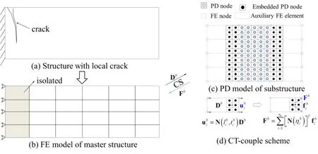
Figure 3:Coupling of PD and NSM
Step 1:The structure with local crack (Fig.3(a)) is discretized into an elastic linear FE model with coarse mesh (Fig.3(b)),and the cracked FE elements (grey elements in Fig.3(b)) are simulated in an isolated substructure using the PD model.A socket connection is established between the ‘grey’ elements and the PD substructure system using the CS technique to transfer displacements and nonlinear force correctors,which will be explained in the next section.
Step 2:The nodal displacements of the cracking elements (e.g.,nodal displacements of cracking and boundary elements) in the master structure system are transferred to the PD substructure through the CS socket.As shown in Fig.3(c),the nodal displacement of thei-thembedded PD node in theb-thauxiliary (boundary) FE element (i.e.,ubi) can be computed by interpolation from the nodal displacements of theb-thauxiliary element Db[Liu and Hong (2012)],i.e.,

wherenbandnneigdenote the numbers of total embedded PD nodes in theb-thauxiliary element and total auxiliary elements,respectively,Dbindicates the displacement vector of theb-thauxiliary element,libandtib
represent the natural coordinates of thei-thembedded PD node in theb-thauxiliary element,those can be obtained by inverse isoparametric mapping from the global coordinate of the PD node [Liu and Hong (2012)].Using the principle of virtual work,the virtual work of the embedded PD nodal force equals to that of the equivalent FE nodal force on the auxiliary elements attributed by the PD nodal force,i.e.,is the force of thei-thembedded PD node in theb-thauxiliary element,Fbdenotes the equivalent nodal force in theb-thauxiliary element contributed by allnbembedded PD nodes.After substituting Eq.(11) into Eq.(12),the equivalent nodal force yields,


In this paper,a ‘CT-couple scheme’ proposed in Liu et al.[Liu and Hong (2012)] was adopted,in which the coupling forces on the embedded PD nodes are divided to the boundary nodes of the auxiliary FE element(see Fig.3(d)).
Step 3:In the master structure model,after accumulating all the equivalent nodal force transferred from the PD substructure,the equivalent resisting force of the cracking elements (i.e.,the central finite elements in the Fig.2(c)) can be obtained as,

After substituting Eq.(14) into Eq.(9),the nonlinear force corrector for the cracking elements yields,

And substitute Eq.(15) into Eq.(10),the equation of motion for the coupling system can be expressed as,

in which,Ksand Dsdenote the stiffness matrix and nodal displacement vector of the crack elements,respectively.
Step 4:After the Eq.(16) is solved for the current time step,the linear elastic elements in the master structure models are checked to see whether there are new crack elements.If no one cracks,the above Steps 2-4 are repeated for the next time step analysis.Otherwise,the FE element is isolated and simulated by using a new PD model,when a new socket connection is established between the PD model and the element in the master structure,as described in Step 1.
3 Numerical implementation
3.1 PD substructure system
In order to quantitate the quasi-static elastic deformation and stationary discontinuous behaviors,artificial damping is a good way to avoid oscillation about the steady-state solution.However,the constant damping coefficient introduced into the PD equation of motion may not be the most effective strategy.Herein,an adaptive dynamic relaxation (ADR) method introduced in Kilic et al.[Kilic and Madenci (2010);Lai,Ren,Fan et al.(2015)] is adopted.
When the damping is considered,the equation of motion for a particle xiin accordance with Eq.(7) can be expressed as,

Therefore,the equation of motion for the whole PD model can be assembled as follows,

where Λ indicates the diagonal mass density matrixdenote positions and displacements at the collocation particles,respectively,Fsis the summation of internal and external forces and itsi-thcomponent yieldscrepresents the damping coefficient.U ′iand X′iare the displacement and coordinate of the neighborhood particles of particle xi.
Without loss of generality,the central difference method,taken as an example,is adopted to solve Eq.(18) in this paper,the update velocity and displacement vectors can be obtained as,

in which superscriptndenotesn-thtime step,Δtis time step size.
In each time step,the damping coefficientcnneeds to be computed to get the fastest path to the steady-state solution,i.e.,

Knis the diagonal “local” stiffness matrix,and its i-th diagonal component yields,

3.2 NSM master structure system
In the master structure system,the central difference method is also adopted to solve Eq.(16),the velocity at the mid-point of the time step and acceleration are given as,

Substitute Eqs.(23)-(24) to Eq.(16),the updated velocity and displacement vectors,respectively,are,

3.3 PD-NSM integration using the CS technique
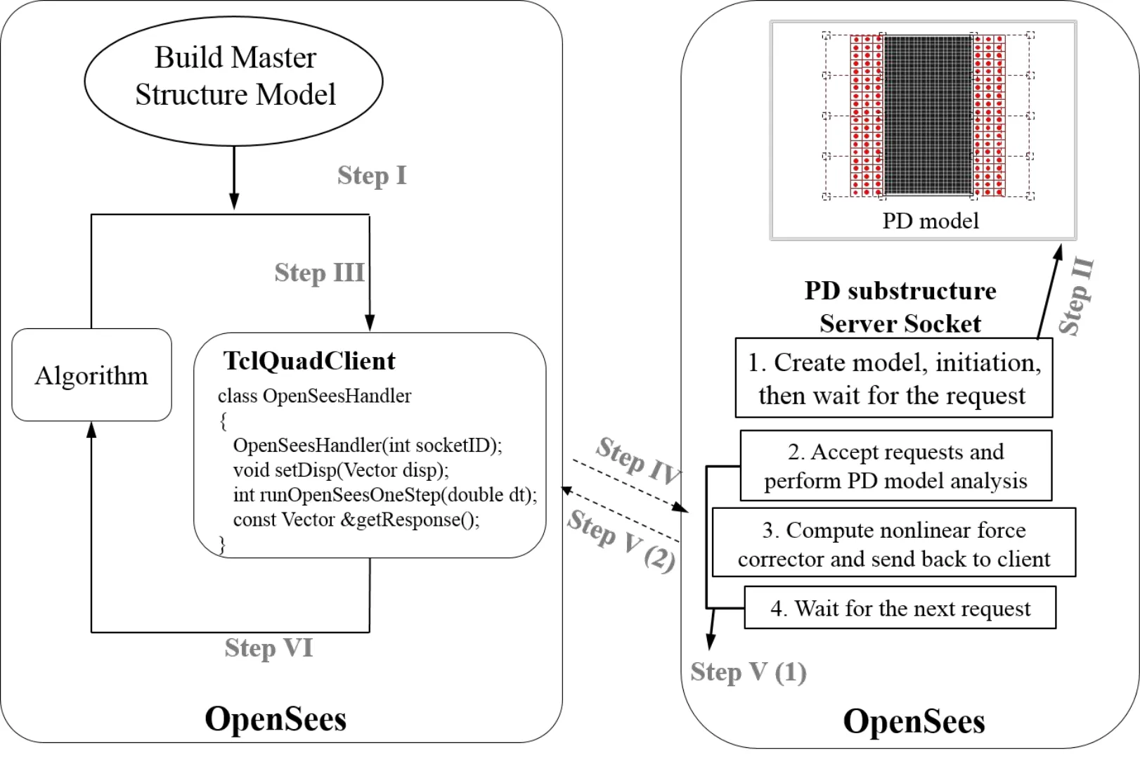
Figure 4:PD-NSM integration by using CS technique
In this study,the PD theory is implemented in an open-source software framework,OpenSees (abbreviated for Open System for Earthquake Engineering Simulation) [Mckenna (1997)].Both the master structure and the PD substructure are simulated by using the OpenSees platforms,as illustrated in Fig.4.The analytical procedures are expressed as follows:
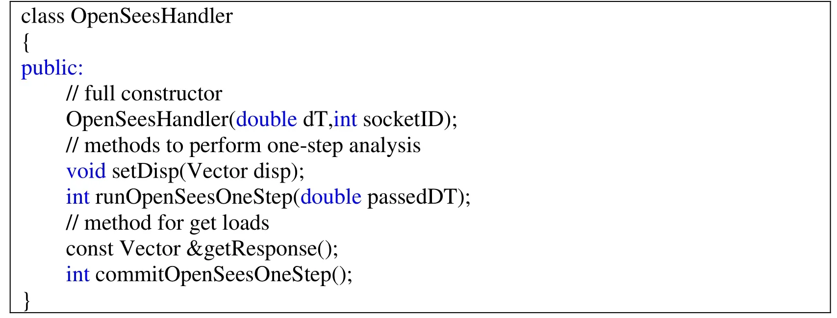
Step I:The master structure is built using 4-node “TclQuadClient” elements,which are similar to the “quad” element and developed in the OpenSees.The developed “TclQuadClient” element has a private object inherited the OpenSeesHandler class,which has following interfaces:
Step II:The PD theory is implemented in the OpenSees platform,therefore,the PD substructure model can be built using aTclscript file,named as “PDmodel.tcl”.After creation and initiation of the PD substructure model,the PD substructure server waits to connect with the master structure (i.e.,client) and then receives and deals with the request from the client.TheTclcommand for connection is:
socket -server accept socketID
in which,socketIDis an integer representing the socket channel number.
Step III:Based on responses of the master structure,determine whether all “TclClient” elements crack or not.Once there exists an element cracks,establish the connection between the “TclClient” element and the PD substructure using the interfaceOpenSeesHandler(double dT,int socket).The developed C++ pseudo-code in the OpenSees can be expressed as:
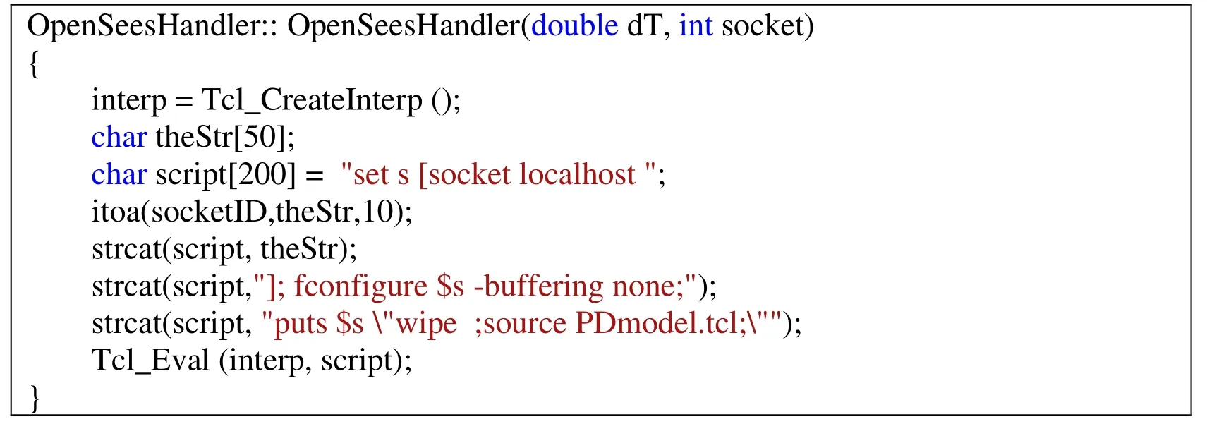
where “int” denotes that integer,socketrepresents the socket channel number,which is consistent withsocketID inthe PD substructure model.
Step IV:The master structure system conducts the numerical calculation and needs to obtain the nonlinear force corrector of the PD substructure,during which the client will send requests to the server,such as,setDisp,runOpenSeesOneStep,andgetResponse;
Step V:(1) After accepting the requestssetDispandrunOpenSeesOneStep,the displacement is applied on the boundary of the PD substructure and then the computation of the nonlinear force corrector is conducted,(2) the server sends back the results to the master structure and then waits for the next request.
Step VI:The master structure accumulates the nonlinear force correctors of all PD substructure servers and solves the governing equation using the central difference algorithm to obtain the responses of the master structure.And then perform the analysis of the next step and repeat Step III-Step VI.
4 Applications
In this section,a concrete cantilever beam with length ofL=1 m,height ofH=0.2 m and thickness of 0.2 m under concentrated load at the free end is investigated to verify the coupling approach,as illustrated in Fig.5.The elastic modulus and the Poisson’s ratio ν are 22 GPa and 1/3,respectively.

Figure 5:Geometry of the cantilever beam under concentrated load at one free end
4.1 Case I:the 2D concrete beam without pre-crack
In this section,the 2D beam without pre-crack is investigated to simulate the crack behavior of concrete material.The crack strains0in the PD substructure model is assumed to be 8e-5.
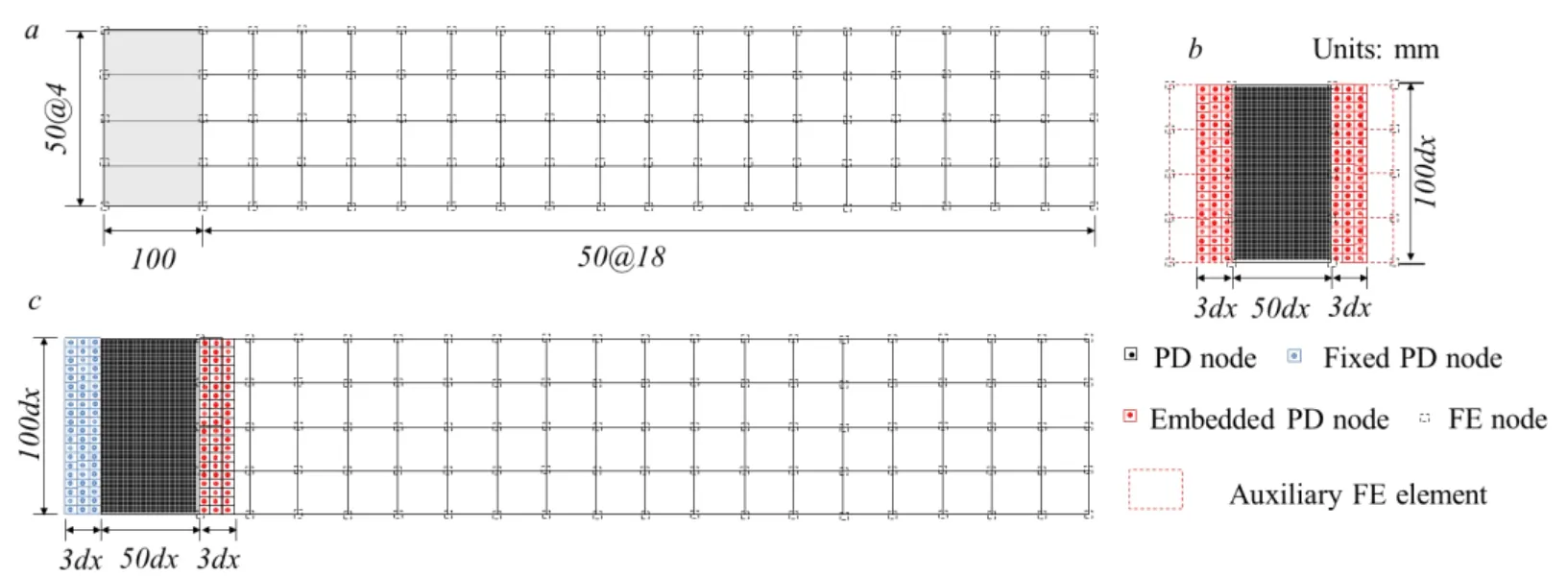
Figure 6:The models for the concrete cantilever beam (a) master FE model (b) PD substructure model (c) PD-FEM coupling model
In the proposed coupling approach,the beam is analyzed using 76 four-node quadratic elements (see Fig.6(a)) with four Gauss points for each element in the master structure.A plane-stress isotropic material constitutive model is adopted to simulate the behavior of the material point.The left cracking regions (e.g.,left four quadratic elements) are isolated and simulated using a PD substructure model (as shown in Fig.6(b)),which has 5000 (50×100) PD nodes and 600 embedded PD nodes.In the PD model,the space griddxand horizonδare taken as 0.002m and 0.006m,respectively,and the bond micromodulusc( 0,δ) is taken as 1.277×10¹⁸N/m6.These parameters remain unchanged in the following sections unless otherwise mentioned.In addition,the conventional FEM and PD coupling approach (i.e.,PD-FEM method) [Kilic and Madenci (2009);Liu and Hong (2012)] is adopted to verify the proposed PD-NSM coupling approach as illustrated in Fig.6(c).
During the analysis process,the concentrated force applied on one free end gradually increases with a load increment of 0.03 N,and the simulation results are recorded in every 500 time-steps.Fig.7 depicts the crack growth and damage of the cantilever beam using the proposed approach.It shows that the ultimate elastic and plastic loads using the proposed coupling approach are 1.545 kN and 1.995 kN,respectively.When the concentrated load exceeds the ultimate elastic load,the crack grows along the vertical direction until the load increases to 1.605 kN (see Fig.7(b)),and then extends towards bottom right when the load ranges from 1.605 kN to 1.775 kN (see Fig.7(c)) and towards bottom until the ultimate load 1.995 kN is reached (Fig.7(d)).

Figure 7:The crack growth obtained using the damage quantification for the cantilever without pre-crack by PD-NSM for increasing loads:(a) 1.545 kN;(b) 1.605 kN;(c) 1.755 kN;(d) 1.995 kN
To verify the proposed coupling method,the traditional PD-FEM coupling approach is used to re-analyze the same problem.The comparative numerical results of the cantilever beam using the PD-NSM and PD-FEM are shown in Figs.7 and 8.From these two figures,we can see that the crack path using the PD-NSM shows good agreement with that using the conventional PD-FEM.

Figure 8:The crack growth obtained using the damage quantification for the cantilever without pre-crack by PD-FEM for increasing loads:(a) 1.545 kN;(b) 1.605 kN;(c) 1.755 kN;(d) 1.995 kN
4.2 Case II:the 2D concrete beam with pre-crack in the left end
The concrete cantilever beam with pre-crack in the left end is investigated in this section.The initial crack is 50 mm depth from the top and located atx= 10mm.The PD-NSM models are given in Figs.9(a) and 9(b).Similar with those in the case I,the beam is built using 76 four-node quadratic elements in the master FE model (Fig.9(a)),and the left pre-crack regions (i.e.,the left four dark elements in Fig.9(a)) are isolated and simulated using the PD substructure model with 4975 PD nodes,600 embedded PD nodes and 8 auxiliary FE elements (as illustrated in Fig.9(b)).In addition,the conventional PD-FEM coupling model is shown in Fig.9(c),which contains 4975 PD nodes,300 fixed PD nodes,300 embedded PD nodes and 72 four-node quadratic elements.
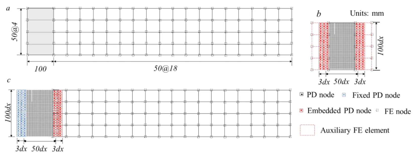
Figure 9:The models for the concrete cantilever beam with pre-crack in the left end (a) master FE model (b) PD substructure model (c) PD-FEM coupling model
The beam with pre-cracked in the left end is analyzed using the proposed PD-NSM approach,and it experiences elastic deformation until the concentrated load increases to 1.02 kN (see Fig.10(a)).Subsequently,the crack propagates along the vertical direction when the concentrated load is 1.125 kN (Fig.11(b)),and then grows along the right bottom direction until it reaches the ultimate plastic load of 1.74 kN,as illustrated in Figs.10(c),10(d).

Figure 10:The crack growth obtained using the damage quantification for the cantilever with pre-crack in the left end by PD-NSM for increasing loads:(a) 1.02 kN;(b) 1.125 kN;(c) 1.305 kN;(d) 1.74 kN.

Figure 11:The crack growth obtained using the damage quantification for the cantilever with pre-crack in the left end by PD-FEM for increasing loads:(a) 1.02;(b) 1.125 kN;(c) 1.305 kN;(d) 1.785 kN
Meanwhile,the pre-cracked beam is re-analyzed using the traditional PD-FEM coupling approach,as shown in Fig.11.The ultimate elastic load is same with that using the PD-NSM coupling approach,while the ultimate plastic load (i.e.,1.785 kN) is a little larger.From Fig.10 and Fig.11,the crack growing path and damage using PDNSM are slightly different with those using the conventional approach.Since a noniterative NSM is used in this paper,the boundary displacement sent from the master structure to the PD substructure in each time step is the previous ones,i.e.,has one-step delay.This may cause numerical inaccuracies and discrepancies between PD-NSM and PD-FEM.An iterative NSM may reduce the discrepancies,as shown in Sun et al.[Sun,Gu,Zhang et al.(2017)].
4.3 Case III:the 2D concrete beam with pre-crack in the middle
The concrete cantilever beam with pre-crack in the middle is studied.The initial crack is located in the middle (x=1000 mm) of the beam.In the proposed PD-NSM approach,the master FE model,as illustrated in Fig.12(a),consists of 76 four-node quadratic elements,in which the middle four element are isolated and simulated in the PD substructure model (Fig.12(b)),and the PD-FEM coupling model is established as shown in Fig.12(c).
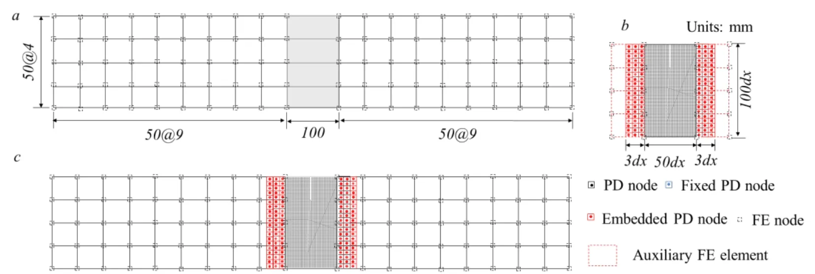
Figure 12:The models for the concrete cantilever beam with pre-crack in the middle (a) master FE model (b) PD substructure model (c) FE-FEM coupling model
The numerical results using the PD-NSM approach are depicted in Fig.13.The pre-crack does not grow until the concentrated load increases to 1.02 kN (Fig.13(a)).After then,it propagates along the vertical direction (see Figs.13(b),13(c)),and goes through the entire section when the load reaches 1.845 kN (Fig.13(d)).

Figure 13:The crack growth obtained using the damage quantification for the cantilever with pre-crack in the middle by PD-NSM for increasing loads:(a) 1.02 kN;(b) 1.17 kN;(c) 1.26 kN;(d) 1.845 kN
The simulating results using the conventional PD-FEM coupling approach are illustrated in Fig.14.By comparing Fig.13 and Fig.14,the crack growing path,the ultimate elastic load (i.e.,1.02 kN) and the ultimate plastic load (i.e.,1.845 kN) using the proposed PDNSM approach are close to those using the conventional PD-FEM approach;and the damages of material using these two approaches are almost the same.

Figure 14:The crack growth obtained using the damage quantification for the cantilever with pre-crack in the middle by PD-FEM for increasing loads:(a) 1.02 kN;(b) 1.17 kN;(c) 1.26 kN;(d) 1.845 kN
5 Conclusion
This paper presents an approach to couple the peridynamic (PD) theory with numerical substructure method (NSM) to simulate the structures with local discontinuities.The bond-based peridynamic theory and the NSM are briefly reviewed.Then the coupling of PD and NSM is presented,in which the structure is simulated using liner elastic finite element (FE) model while the local cracking regions are isolated and simulated using PD substructure models.A force corrector is calculated from the PD model and applied on the FE model to account for the contribution of the discontinuities.The PD model is integrated in the substructure model using interface elements with embedded PD nodes.The equations of motions of both NSM system and PD substructure are solved using the central difference method.Finally,three examples of two-dimensional (2D) concrete cantilever beams under the concentrated force at the free end are investigated.The analysis results are verified by using traditional PD-FEM coupling approach.It is observed that the PD-NSM approach shows good agreement with the PD-FEM in the sense of the crack growth behaviors,the ultimate elastic load and the ultimate plastic load.The presented method of coupling PD and NSM are demonstrated to be an effective method for modeling structures with local discontinuities.
Acknowledgement:Financial support by the National Key Research and Development program of China under Grant No.2016YFC0701106,the National Natural Science Foundation of China under grants No.51578473,and the program of China Scholarship Council (CSC,No.201606060083) are gratefully acknowledged.
 Computer Modeling In Engineering&Sciences2019年9期
- Computer Modeling In Engineering&Sciences的其它文章
- Structural Finite Element Software Coupling Using Adapter Elements
- Fragility Assessment of Pre-Northridge Steel Moment Frames Using Finite-Length Plastic Hinge Elements and Concentrated Plasticity Fracture Elements
- The Behavior of Rectangular and Circular Reinforced Concrete Columns Under Biaxial Multiple Excitation
- Real-Time Hybrid Simulation of Seismically Isolated Structures with Full-Scale Bearings and Large Computational Models
- Experiment and Simulation for Controlling Propagation Direction of Hydrofracture By Multi-Boreholes Hydraulic Fracturing
- Determination of Working Pressure for Airport Runway Rubber Mark Cleaning Vehicle Based on Numeric Simulation
