Time-Domain Analysis of Underground Station-Layered Soil Interaction Based on High-Order Doubly Asymptotic Transmitting Boundary
Tingjin Liu ,Siyuan Zheng,Xinwei Tang , , and Yichao Gao
Abstract: Based on the modified scale boundary finite element method and continued fraction solution,a high-order doubly asymptotic transmitting boundary (DATB) is derived and extended to the simulation of vector wave propagation in complex layered soils.The high-order DATB converges rapidly to the exact solution throughout the entire frequency range and its formulation is local in the time domain,possessing high accuracy and good efficiency.Combining with finite element method,a coupled model is constructed for time-domain analysis of underground station-layered soil interaction.The coupled model is divided into the near and far field by the truncated boundary,of which the near field is modelled by FEM while the far field is modelled by the high-order DATB.The coupled model is implemented in an open source finite element software,OpenSees,in which the DATB is employed as a super element.Numerical examples demonstrate that results of the coupled model are stable,accurate and efficient compared with those of the extended mesh model and the viscous-spring boundary model.Besides,it has also shown the fitness for long-time seismic response analysis of underground station-layered soil interaction.Therefore,it is believed that the coupled model could provide a new approach for seismic analysis of underground station-layered soil interaction and could be further developed for engineering.
Keywords: Time-domain analysis,layered soil,scaled boundary finite element method,transmitting boundary,continued fraction.
1 Introduction
The fast development of urbanization has catalyzed for underground space exploitation,especially urban rail transit.The dynamic response of embedded structures in layered soil such as metro station and tunnels is greatly affected by soil-structure interaction (SSI) [Wolf (1989)],of which the radiation damping of the semi-infinite foundation is the main difficulty and key point of simulation.Extensive numerical approaches have been developed over the past 40 years to model the unbounded domain.Most of them could be summarized as approximate and rigorous methods.Approximate methods like the artificial boundary conditions [Dan (1999,2004)] are spatially and temporally local,which are computationally efficient but must be set with a quite distance from the interested region to obtain required accuracy [Lysmer (1969)].Besides,most of the artificial boundaries are only singly asymptotic at high-frequency,resulting in a very high order of approximation for reasonable accuracy [Hagstrom and Hariharan (1998)] when confronting the evanescent wave decayed promptly in semi-infinite layered medium.While rigorous methods like the boundary element method (BEM) [Estorff and Hagen (2005);Luco and Barros (2010)],the thin layer method (TLM) [Kausel and Peek (1982);Kausel (2010)] and the scaled boundary finite element method (SBFEM) [Song and Wolf (1997);Wolf (2004)] are spatially and temporally global,thus computationally expensive.The SBFEM is a semi-analytical method,of which only the boundary is discretized and no fundamental solution is required to satisfy the damping condition of unbounded domain.Therefore,it is an appealing method for researching the unbounded domain.The application of the SBFEM could be found in Bazyar et al.[Bazyar and Song (2010a,2010b);Bransch and Lehmann (2011);Yaseri,Bazyar and Hataf (2014)],but it is still lack in efficiency because of globalization in the time domain,restricting the broad application of SBFEM.
To balance well between accuracy and computational efficiency,there are many researches on the application of SBFEM in layered soils.Birk et al.[Birk and Behnke (2012)] modify the SBFEM in the case of layered soils by replacing the scale center with line and successfully apply it to the three-dimension problems.Chen et al.[Chen,Birk and Song (2015)] apply SBFEM to elastic wave propagation simulation in layered soil in the time domain.However,it is time-consuming because of convolutional integration solution.Based on the SBFEM,Bazyar et al.[Bazyar and Song (2008)] construct a highorder transmitting boundary using continued fraction solution,realizing time localization.Extra factor matrices are introduced by Birk et al.[Birk and Song (2009)] to improve the numerical stability,making it suitable for large-scale problems.However,it could not model evanescent waves because of singly asymptotic at high-frequency and only the propagating waves is absorbed.Hence,a high-order doubly asymptotic transmitting boundary (DATB) is proposed by Prempramote et al.[Prempramote,Song,Tin-Loi et al.(2010)] for scalar wave propagation in semi-infinite layered medium,in which continued fraction solution is expanded at both high and low frequency,obtaining dynamic stiffness solution closed to the exact solution.Wang et al.[Wang,Jin,Prempramote et al.(2011)] and Gao et al.[Gao,Jin,Wang et al.(2011)] expand this boundary to unbounded reservoir and apply it with FEM to the seismic response analysis of dam-reservoir systems.Furthermore,the high-order DATB is applied for problem of vector wave propagation in single layered soil [Prempramote (2011)].However,it does not go further application on complicated layers situation.
In all,lots of researches have concentrated on the solution in the frequency domain and it is still relied on time-consuming convolutional integration solution in the time domain,resulting in low efficiency.Besides,it is rarely reported the application of high-order DATB on time-domain analysis of underground station-layered soil interaction,especially in multiple layered soils.
In this paper,the excellent high-order DATB is extended to simulation of the vector wave propagation in the complicated layered soils.Combining the high-order DATB with the finite element method (FEM),a coupled model is constructed for the seismic response analysis of the realistic complicated underground station-layered soil systems.The coupled model is numerically implemented in OpenSees to study the seismic response of the underground station-layered soil systems.OpenSees,the open system for earthquake engineering simulation (http://opensees.berkeley.edu),is an open source general purpose finite element software for modeling structural and geotechnical systems.The accuracy and efficiency of the coupled model are validated by numerical examples.
2 Summary of SBFEM of semi-infinite layers with constant depth
Underground station is usually buried in the complicated layered soils.Thus,the key equations of the SBFEM for vector wave problem in layered soils [Prempramote,Song,Tin-Loi et al.(2010)] are briefly presented in this section.
As shown in Fig.1,elastic semi-infinite layers with constant depth are assumed to be isotropic.As a special case,the scaling center of semi-infinite layers in the SBFEM is located at infinity [Li,Cheng,Deeks et al.(2005)].The model is divided into the near field and far field by the truncated boundary.One-dimensional line element is brought in to discretize the truncated boundaryBvshown in Fig.1(a) and a typical line element is shown in Fig.1(b).Besides,free boundary condition is imposed on the upper boundaryBuand fixed boundary condition is imposed on the bottom boundaryBb.
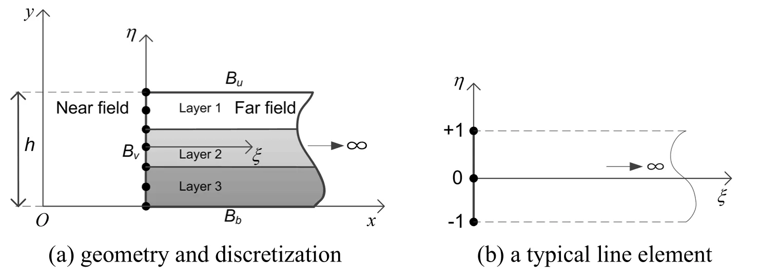
Figure 1:Elastic semi-infinite layers with constant depth
The geometry of the line element in the scaled boundary coordinates (ξ,η) is expressed as

whereξ≥ 0 (ξ= 0 denotes the vertical boundaryBv),[N(η) ] is the shape function vector formulated in the coordinateηand {yb} is the vertical coordinate vector of nodes on the vertical boundaryBv.
For two-dimensional problem of semi-infinite layers,the scaled boundary finite element (SBFE) equation in displacement is derived by using the scale boundary transformation as well as Galerkin weighted residual method and formulated in the frequency domain as

where the coefficient matrices are independent ofξand defined in the Prempramote [Prempramote (2011)].
The dynamic stiffness matrix of an unbounded domain [S∞(ω)] (superscript ∞ denotes for unbounded domain) is defined by the excitation force-displacement relationship as

where {R} is nodal forces on the truncated boundary.
Following the derivation in Prempramote [Prempramote (2011)],Eq.(2) can be transformed into the formulation in dynamic stiffness as

whereωis the excitation frequency.Based on Eq.(4),the high-order DATB could be constructed with the help of continued fraction solution and would be described in Section 3.
3 High-order doubly asymptotic transmitting boundary
In this section,continued fraction solution is applied in Eq.(4) to approximate the dynamic stiffness matrix of unbounded domain at both high-frequency and lowfrequency range.The transmitting boundary condition is constructed using the continued fraction solution of dynamic stiffness matrix and the auxiliary variable technique.The solution process of the continued fraction expansion at both high frequency and low frequency range can be found in Prempramote [Prempramote (2011)],only the key equations are presented.
To start with,the continued fraction solution is firstly determined at the high-frequency limit (ω→∞) and is expressed as

where [K∞] and [C∞] are stiffness matrix and damping matrix of unbounded domain respectively.[Y0(i)] and [Y1(i)] are coefficient matrices to be determined recursively in the solution procedure.[X(i)] is the factor matrix introduced to improve numerical stability.MHis the order of the continued fraction solution at high frequency range.
To determine a valid solution over the whole frequency range,the continued fraction solution for the residual of the high frequency range is constructed at the low-frequency limit (ω→ 0).Introducing [YL(ω) ]=[Y(MH+1)(ω)],the continued fraction solution of [YL(ω)] at the low-frequency limit is expressed as

Substituting continued fraction solution of dynamic stiffness matrix (Eqs.(5)-(6)) into Eq.(3) as well as introducing auxiliary variables,the high-order DATB in the frequency domain is constructed.Apply the inverse Fourier transform,this transmitting boundary is formulated in the time domain as:

where [KZ] is the generalized stiffness matrix and [CZ] is the generalized damping matrix.{uz} denotes the displacement amplitude and the auxiliary variables on the boundaryBv.{fz} denotes the amplitude of the excitation forces on the boundaryBv.All of them are the frequency-independent coefficient matrices and defined as:

where the block matrices [K1],[KA] and [CA] are defined as
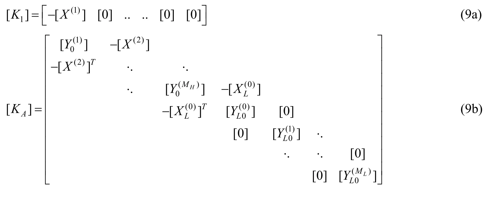

where subscript “A” represents the auxiliary variables.
Eq.(7) is a first order ordinary differential equation and can be solved using the standard time integration scheme,such as Newmark method.Thus,the time-consuming convolutional integration is avoided in the transient analysis and the computational efficiency is improved.
4 Coupled model and implementation in OpenSees
Employing the same grids and shape functions at the common boundary (i.e.,Bv),the high-order doubly asymptotic transmitting boundary can be seamlessly coupled with FEM.Regardless of material damping,the finite element equation modeling near-field in the time domain is expressed as

where matrices [M] and [K] stand for the mass matrix and the stiffness matrix respectively,subscript “s” denotes all the other degree of freedom except those on the boundary and “b” denotes the degree of freedom on the boundary.{us} and {ub} are the displacement vector.{fs} and {rb} are the nodal force vector.
Combining Eqs.(7) and (10),the coupled model could be built.As the coefficient matrices of Eq.(8) result from the repeated inversion in the continued fraction solution,possible spurious modes may exist,resulting in the instability of Eq.(10).To guarantee the numerical stability,a spectrum shifting technique is proposed by Birk et al.[Birk,Prempramote and Song (2012)] to remove spurious modes,where [KZ] is modified while [CZ] remains still.
Marking superscript “~” for modification of the stiffness matrices,the coupling equation is obtained by substituting Eq.(7) into Eq.(10) as:

Eq.(11) has the same characteristics as the finite element equation,i.e.,the coefficient matrices are symmetric and sparse.This coupled model is implemented in the open source finite element software OpenSees.The high-order DATB is employed as a super element in OpenSees.As the coeffect matrices of the super element are constant,they can be solved only once by MATLAB and read into OpenSees during the analysis.The main solution procedure of the coefficient matrices in MATLAB are summarized as Fig.2.
Moreover,the TCL (Tool Command Language) script for the input of the DATB super element is also generated by MATLAB.As the coefficient matrices of the DATB super element is solved and stored in binary file before the transient analysis,the DATB super element in OpenSees simply reads in the coefficient matrices according to the analysis procedure and thus computationally efficient.
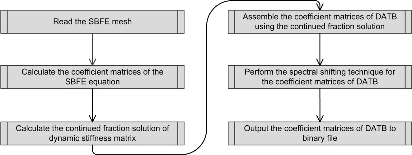
Figure 2:The main solution procedure of the coefficient matrices in MATLAB
5 Numerical examples
In this section,the accuracy and efficiency of the coupled model are examined in the time domain by two numerical examples.As the coupled model is constructed on the highorder DATB,the results of the coupled model are denoted by DATB for simplicity.The extend mesh model (EMM) is analyzed by FEM to provide a reference solution.Besides,the viscous-spring boundary model [Liu,Du,Du et al.(2006)] (VSB) is also employed to make a comparison with DATB.All the methods are conducted through using the open source finite element software OpenSees.
In Section 5.1,surface traction is applied at double semi-infinite layered soil.And in Section 5.2,a metro station buried in double layered soil subjected to El-Centro seismic wave is analyzed.Moreover,in Section 5.3,the calculation efficiency is discussed among numerical examples.
5.1 Semi-infinite layered soil under surface traction of triangular impulse
In this example,the double semi-infinite layered soil subjected to surface traction in the inclined direction of 45° is illustrated in Fig.3.The top of the soil is free boundary condition and the bottom of the soil is fixed.Both have the height of 0.5.The material properties of soils are presented in Fig.3.
Standard four-node quadrilateral element in OpenSees is selected to model near and far field for plane-strain condition.The near field needs to be discretized with 100 quadrilateral elements (size of element is 0.1×0.1).As for the boundary between near and far field,10 two-node line elements of equal length are used for discretization in the DATB model.While for the EMM,total discretization area is 80×1 so that responses are not affected by the waves reflected at the truncated boundary under correspondingly analyzing time.8000 quadrilateral elements (size of element is 0.1×0.1) are used for discretization.
The time history of triangle impulsep(t) is plotted in Fig.4 and the maximum surface traction is denoted asP.The total analyzing time is 30 and the dimensionless time step Δtis 0.1.
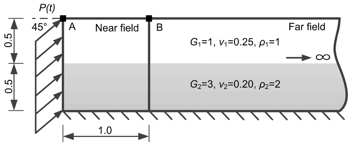
Figure 3:Double semi-infinite layered soils subjected to inclined surface traction
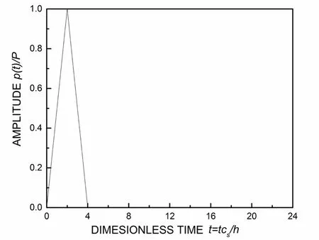
Figure 4:Time history of triangular impulse
The accuracy of the DATB is investigated with the order ofMH=ML= 4.The displacement responses at Point A and B are plotted in Figs.5 and 6,respectively.Excellent agreement is shown between the response of the DATB and the EMM through the whole calculating time,demonstrating the high accuracy of the DATB.As for the VSB,unsatisfactory results can be seen in both Point A and B.Besides,the results of Point B deviate much more from the EMM than those of Point A,manifesting a significant error at the boundary of the VSB.It is indicated the deficiency of the VSB in the long-time dynamic analysis.
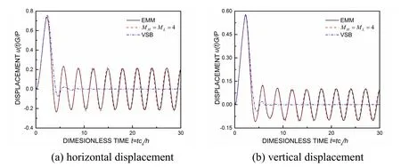
Figure 5:Displacement responses at point A
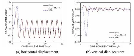
Figure 6:Displacement responses at point B
5.2 Metro station embedded in semi-infinite layered soil
In Section 5.2,a metro station embedded in semi-infinite layered soil is studied under El-Centro wave.Two layered soils are selected and the metro station is chosen as doublelayered island platform station.
As shown in Fig.7,the physical dimension of the near field model is 66 m×55 m and the metro station is horizontally located in the middle of near field.The top of the soil (the ground surface) is free boundary condition and the bottom of the soil is fixed.Three observant Point A,B and C are selected for displacement.
As depicted in Fig.8,the metro station is mainly consisted of the roof slab (RS),the middle slab (MS),the base slab (BS),the lateral wall (LW) and the columns.The thickness of RS,MS,BS and LW is 0.8 m,0.5 m,0.9 m and 0.8 m,respectively.The columns are spatial in practical and the principle of equivalent stiffness is introduced considering the plane-strain condition.Therefore,the width of the columns is equivalent to 0.4 m.
The near field soils are modeled by 3300 quadrilateral elements (size of elements is 1 m×1 m).Another 55 two-node line elements are used for discretizing the vertical boundary to model far field in the DATB.As for the EMM,the entire discretization area is determined as 3000 m×55 m.Totally 84171 elements are used to model near field soil as well as underground station in the EMM.186 quadrilateral elements are applied to model the metro station.The metro station is assumed to deform together with the soils during the seismic as one kind of the soil-structure interaction (SSI).Therefore,the common girds are shared by station and soils in modeling.The mesh model of the near field is illustrated in Fig.9.
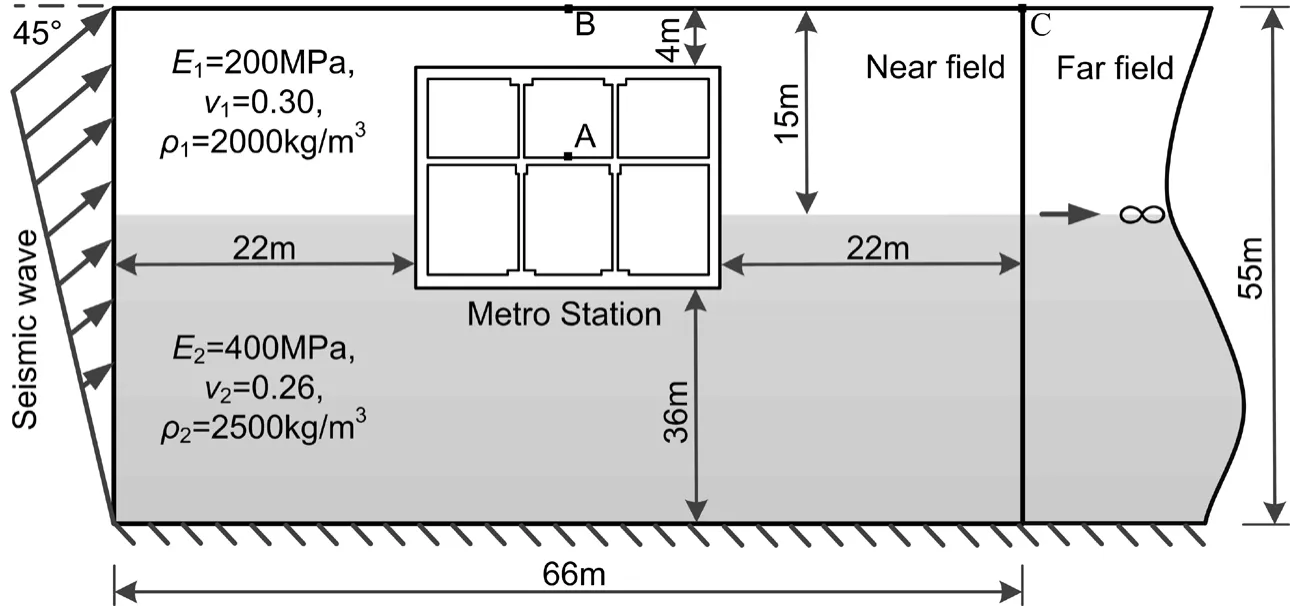
Figure 7:Metro station embedded in semi-infinite layered soil suffered by El-Centro wave
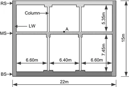
Figure 8:Details and geometry of the metro station

Figure 9:The mesh model of the near field
The material constants of the soils are presented in Fig.7.And material of the metro station is C30 concrete with the Young’s modulusEc= 3000 MPa ,mass density c onsidered as elastic constitutive model.ρc= 2500 kg/m3and Poisson’s ratioνc= 0.20.Both the metro station and the soils are
El-Centro wave is selected as input seismic wave and loaded as the time history of acceleration at the nodes on the left boundary in Fig.7.It is triangularly inclined distributed at a direction of 45° to horizontal line.The time history of acceleration of El-Centro wave and its Fourier transform are plotted in Fig.10.The entire duration lasts for 10s and time step Δtis 0.02 s.

Figure 10:El-Centro seismic wave
The comparisons of the displacement responses under El-Centro wave among the DATB,the VSB and the EMM are shown in Figs.11,12 and 13.The DATB is calculated with an orderMH=ML= 4.It can be observed from three figures that excellent agreement exists between the DATB and the EMM in both horizontal and vertical displacement among three observant points.However,the results of the VSB are less accurate compared with the DATB.Similar as the observations from Section 5.1,the results of the boundary (Point C) as plotted in Fig.13 have a much more deviation than those of the inside points (A and B).
Through the examples,it can be concluded that the DATB is much more accurate in modeling semi-infinite layered medium as well as solving time-domain problem than the VSB.The excellent agreement in Section 5.2 between the DATB and the EMM indicates that the DATB might be applicable to practical engineering project.
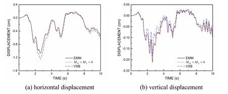
Figure 11:Displacement responses at point A

Figure 12:Displacement responses at point B

Figure 13:Displacement responses at point C
5.3 Comparison of the calculation efficiency
To evaluate the efficiency of the coupled model,the computer times spent on the above time-domain analyze of two numerical examples are listed in Tab.1.The times are recorded on a desktop computer with an Intel(R) Core(TM) i7-6700K 4.00 GHz CPU and 48.0 GB of RAM.In Tab.1,numerical examples (1) and (2) represent the example in Section 5.1 and metro station example in Section 5.2.
For numerical example Ⅰ as well as Ⅱ,the calculation time of the DATB is close to that of the VSB,showing a good efficiency while ensuring a high accuracy.Therefore,it is shown that high-order doubly transmitting boundary balances well between accuracy with efficiency as it can greatly improve the accuracy while does not spend too much time.

Table 1:Comparison on computer times of numerical examples
So far,the high-order doubly asymptotic boundary has been proved accurate and efficient.It is demonstrated that this coupled model is well suitable for long-time analysis of underground station-layered soil interaction in the time domain.
6 Conclusions
The high-order DATB is extended to the simulation of elastic wave propagation in semiinfinite multiply layered soils.This transmitting boundary converges to the exact solution rapidly throughout the entire frequency range.A coupled model is constructed by combining the excellent DATB and FEM.This coupled model is implemented in the open source finite element software OpenSees by employing a super element representing the high-order DATB.The coefficient matrices of the super element are constant matrices and solved only once by MATLAB.
Numerical examples have witnessed the accuracy and efficiency of the coupled model.The coupled model is of high accuracy as excellent agreement shown between the results by DATB and the EMM.While compared with the VSB,the coupled model does not spend too much time on calculation,showing a better balance of accuracy and efficiency.It is also demonstrated that the coupled model is suitable for long-time analysis of underground station-layered soil interaction.Besides,the coupled model is achieved through OpenSees and can be further developed for engineering application.
Acknowledgement:This research investigation was supported by the National Natural Science Foundation of China (Grant No.51678248 and Grant No.51878296) and the Fundamental Research Funds for the Central Universities.And sincere thanks also to State Key Lab of Subtropical Building Science,South China University of Technology under Grant No.2017KB15 and the Open Research Fund of State Key Laboratory of Simulation and Regulation of Water Cycle in River Basin under Grant No.IWHRSKL- KF201818.
 Computer Modeling In Engineering&Sciences2019年9期
- Computer Modeling In Engineering&Sciences的其它文章
- Coupling of Peridynamics and Numerical Substructure Method for Modeling Structures with Local Discontinuities
- The Behavior of Rectangular and Circular Reinforced Concrete Columns Under Biaxial Multiple Excitation
- Real-Time Hybrid Simulation of Seismically Isolated Structures with Full-Scale Bearings and Large Computational Models
- Structural Finite Element Software Coupling Using Adapter Elements
- Experiment and Simulation for Controlling Propagation Direction of Hydrofracture By Multi-Boreholes Hydraulic Fracturing
- Determination of Working Pressure for Airport Runway Rubber Mark Cleaning Vehicle Based on Numeric Simulation
