
Radial consolidation characteristics of soft undisturbed clay based on large specimens
2018-12-20 11:11PnkjBrlCholchtRujikitkmjornBuddhimIndrrtnRichrdKelly
Pnkj Brl,Cholcht Rujikitkmjorn,Buddhim Indrrtn,*,Richrd Kelly
aResearch Centre for Geomechanics and Railway Engineering,Faculty of Engineering and Information Sciences,University of Wollongong,Wollongong,NSW,2522,Australia
bSMEC-Australia and New Zealand Division,Brisbane,Queensland,Australia
Keywords:Consolidation Soft soil Vertical drain Undisturbed clay
A B S T R A C T In recent years,reconstituted small samples have often been used to assess the performance of radial consolidation due to prefabricated vertical drains(PVDs),but the permeability and compressibility of samples of undisturbed soil often differ from those of the remoulded ones.The problem seems more complex in marine environment due to the presence of random coarse particles including gravels,shells and natural partings.Performing small-scale laboratory experiment with reconstituted samples,especially in marine environment,cannot predict the exact soil behaviour in the field.This paper describes an experimental programme that measures radial consolidation using a conventional Rowe cell and a largescale consolidometer,where the samples of undisturbed soil obtained from a site along the Pacific Highway(north of Sydney)were compared using measured settlements and excess pore pressures.Moreover,this paper highlights the implications of the smear effect and sample size influence,which are imperative in translating the laboratory testing practices to actual real-life behaviour.The effect of vacuum pressure on the coefficient of radial consolidation of a large-scale undisturbed test specimen is also discussed.The paper demonstrates that the extent of smear zone in the field can be very similar to the large-scale laboratory consolidation test using a scaled-down drain and mandrel,but considerably different from the data obtained for small laboratory specimens.
1.Introduction
Advancements in soil improvement techniques over recent years have led to the construction of a number of highways and railway embankments over deposits of soft soil using stone columns,piles,vibro-compaction and preloading combined with prefabricated vertical drains(PVDs),etc.Among them,PVDs combined with surcharge and vacuum preloading are used to limit the post-construction excessive and differential settlement of highly compressible soil with very low undrained shear strength(i.e.<5 kPa),by prior consolidation of the soil.PVDs are mainly used to reduce the drainage path and they hasten the dissipation process of excess pore water pressure.Their effectiveness has been proven in many ground improvement projects and land reclamation work in coastal Australia and other parts of the world(Bergado et al.,1991;Chai and Miura,1999;Indraratna and Redana,2000;Arulrajah et al.,2004;Chai et al.,2004;Chu et al.,2004;Bo et al.,2005;Hansbo,2005;Indraratna et al.,2005a,b,2018;Rowe and Li,2005).It is imperative to evaluate the soil properties using laboratory specimens in order to match the field conditions,so that the rate of compression as well as the consolidation time can be accurately predicted.According to Rowe(1968)and Garga(1988),the compressibility parameters obtained via conventional laboratory equipment using oedometer samples cannot always be used to accurately predict the rate of consolidation in the field.Later,Larsson and Mattsson(2003)used an oedometer to test a relatively small sample(50 mm in diameter)and found that a central drain resulted in a higher rate of compression in the laboratory compared to field conditions.This implies that in order to accurately evaluate or predict the performance of PVDs,a consolidation test should mimic in situ conditions as accurately as possible,especially the rate of compression,the direction of flow during consolidation and the type of soil.
Application of vacuum along with surcharge preloading in the embankment stabilised with PVDs accelerates the excess pore water pressure dissipation more rapidly and prepares the ground for superstructure construction faster compared with an embankment stabilised with PVDs only.Several case studies have been conducted worldwide to investigate the effectiveness of vacuum in ground improvement projects;accordingly,there exist numerous analytical and numerical models describing the theory of vacuum consolidation (Qian et al.,1992; Bergado et al.,2002;Mohamedelhassan and Shang,2002;Indraratna et al.,2005a,b).
This paper describes a comparison between the consolidation of samples of undisturbed soil using a large-scale consolidometer(US1)of 350 mm in diameter and 700 mm in height,a Rowe cell(US2)of 75 mm in diameter and 20 mm in height,and a large-scale consolidometer(US3)of the same dimensions as US1 but with the application of vacuum pressure.In this comparison,the coefficients of radial consolidation for all three samples were evaluated based on the settlement and pore water pressure measurements.This paper also provides a corroboration between the coefficients of radial consolidation obtained from large undisturbed samples and conventional Rowe cell testing.In addition,it gives significant insight to the vacuum consolidation techniques applied to undisturbed samples encompassing the scale effect and other limitations of laboratory testing.Moreover,the coefficients of radial consolidation and permeability within the undisturbed zone with and without the effect of vacuum pressure(US3)are also compared.
2.Testing programme
Soft clay samples in marine environment were obtained from a trial site(BFTF)along the Pacific Highway in the town of Ballina,south of Brisbane(see Fig.1).A sample of undisturbed soil was extracted from a depth of 1.5 m,and the sub-soil within 1.3-2.2 m depth can be classified as highly compressible marine clay with very low permeability and high plasticity(CH).The basic properties obtained from this undisturbed soil sample are tabulated in Table 1.The values of undrained shear strength are taken from Indraratna et al.(2015)using field vane testing.

Fig.1.Location of extracted sample(BFTF,Ballina,New South Wales).
To extract this sample of undisturbed soil(US1),a 350 mm diameter by 700 mm long cylindrical corer was pushed into the soil by a light excavator to a depth of 1.5-2.2 m;this static push method prevents the corer from rotating,thus ensuring a high-quality sample(Andresen and Kolstad,1979).Furthermore,the quality of sample in relation to the degree of disturbances was ensured by calculating the area ratio for 5 mm wall thickness and 345 mm internal diameter,which turned out to be as small as 2.9%,confirming that the degree of disturbance during retrieval stage was insignificant,because this ratio(i.e.2.9%)was far less than 10%(Hvorslev,1949).The corer also had a top cap that stops any loss of moisture whilst being pushed into the ground.After the corer was filled with soil,the surrounding soil was excavated and then the corer was removed from the bottom of the pit.The sample was then trimmed to remove the excess height(which prevented the disturbance of the sample top)and sealed at both ends with wax.Both end caps were re-attached and tightened so that there was no air gap at both ends of the sample.This technique also helps to prevent any stress relief.The samples were then transferred to the laboratory and stored in a room with controlled humidity(refer to Fig.2 for the sample extraction technique).
Testing procedures for a large-scale consolidometer with a 350 mm diameter specimen under both vacuum and surcharge loading conditions and a conventional Rowe cell(75 mm diameter specimen)are described herein.
2.1.Large-scale consolidometer
A schematic diagram of the combined two-in-one large-scale corer and consolidometer is shown in Fig.3.It consists of a cylindrical corer,a loading rig platform and rig,and a pneumatic air pressure chamber as follows:
(1)Cylindrical corer:The corer was manufactured by rolling 5 mm thick steel plate into a 350 mm diameter by 700 mm long cylinder and then it was cut longitudinally into two halves.Teflon spray was applied to the inner wall to reduce friction,and two pore pressure transducers were located beneath the bottom lid:one at the centre and one 96.25 mm from the centre.A custom-made piston with two O-ring grooves could transfer the load from a pneumatic air pressure chamber on top of the sample.O-rings were placed into the grooves to prevent air or water leakage.
(2)The platform and loading rig:The lower part of the corer was attached to the base of the platform while the upper part of the corer,along with the piston and air pressure chamber,was attached to the loading rig.
(3)The pneumatic air pressure chamber:An air pressure chamber was used to provide the required amount of load to the sample during testing,and a load cell was used to measure the load applied onto the sample.
A traditional band-shaped drain(100 mm×3 mm),based on the equivalent diameter and spacing in the field,was scaled down for the purpose of laboratory simulation,hence a model PVD of 25 mm×3 mm(i.e.equivalent wick drain radius,rw=7 mm)was used.A hollow rectangular mandrel(30 mm×5 mm)was used to insert the model PVD into the laboratory sample.This hollow rectangular mandrel had an equivalent mandrel diameter(dm)of 13.8 mm.The model PVD was installed by pushing the mandrel at a constant speed along a vertical guide to the required depth inside the corer containing the undisturbed sample(US1),and then withdrawing it immediately after reaching the sample base.A linear variable differential transformer(LVDT)was connected on top of the piston to measure the vertical displacement of the sample.Two pore water pressure transducers were connected to the bottom base at different locations,and then the undisturbed sample(US1)was compressed under an axial pressure of 80 kPa.As the yield stress(i.e.maximum past pressure)for this clay was measured earlier to be 67 kPa from oedometer tests,which is in the range of 65-70 kPa for the same depth as reported by Pineda et al.(2016),the consolidation under the currently applied load could ensure compression of the test specimen along the normally consolidated line.

Table 1 Properties of Ballina clay(at 1.3-2.2 m depth).

Fig.2.Sample extraction procedure:(a)Excavation of trench,(b)Insertion of cylinder cum corer(350 mm diameter),(c)Large-scale sample with undisturbed Ballina clay,and(d)Transporting undisturbed specimens to University of Wollongong(UOW)laboratory.
2.2.Rowe cell testing
A sample(US2)of 75 mm in diameter and 20 mm in thickness was extruded from an 85.9 mm long piston sampler and then subjected to radial consolidation inside a Rowe cell(Fig.4)that was originally developed by Rowe and Barden(1966).A 40-50 mm thick portion was cut from the sampling tube using a pipe vice.A thin wire was rotated around the internal periphery of the sampling tube to separate the sample from the sampler.This sample was further trimmed using a turning trimmer made at UOW;a 20 mm thick sample was cut from the larger sample,and then a 5.35 mm diameter sand drain was inserted through the centre of the small sample.The pre-bored sand drain was installed at the centre of sample in a non-displacement manner so that the occurrence of smear during installation was insignificant.For the purpose of comparison,both small and large samples(350 mm in diameter)were retrieved from the same depth and had the same drain to equivalent diameter ratio(n).In addition,all three samples were subjected to back pressure to ensure 100%degree of saturation prior to loading and Skempton’sBparameter >0.95 to ensure the consistency.The sample of undisturbed soil(US2)was then subjected to a surcharge load of 80 kPa.
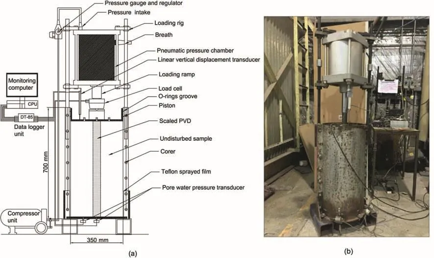
Fig.3.Large-scale consolidometer with US1:(a)Schematic diagram,and(b)Laboratory setup.
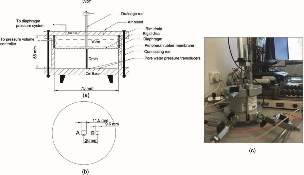
Fig.4.75 mm diameter Rowe cell with US2:(a)Schematic diagram,(b)Baseplate showing the location of the pore pressure transducers,and(c)Laboratory setup.
2.3.Large-scale consolidometer with vacuum preloading
The large-scale consolidometer(as described in Section 2.1)was modified to allow lateral deformation of the undisturbed sample(US3).The modification includes the installation of a 1.5 mm diameter porous plastic sheet around the inner wall of the corer with a 1.5 mm thick rubber membrane between the sample and the porous plastic sheet(Fig.5).A rim drain was then fitted around the piston and connected to a pressure volume controller.The rubber membrane and the wall of the corer can be separated upon the inward movement of the soil due to vacuum consolidation.Based on the volume of water flow in the gap between the wall and the rubber membrane with time,the lateral deformation of the sample could be calculated.A surcharge load of 20 kPa and a vacuum pressure of 60 kPa(vacuum surcharge ratio,VSR=0.75)were applied to the consolidometer(US3).
3.Results and discussion
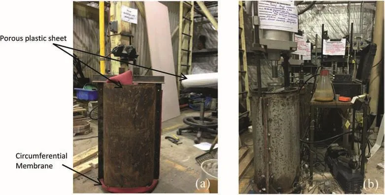
Fig.5.(a)Installation of membrane around the undisturbed specimen for vacuum case(US3),and(b)Final setup of sample for vacuum case.
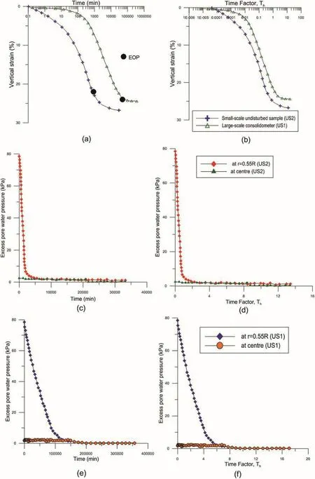
Fig.6.(a)Strain-time curves,(b)Strain-time factor curves,(c)Excess pore water pressure curves for US2 with time,(d)Excess pore water pressure curves for US2 with time factor,(e)Excess pore water pressure curves for US1 with time,and(f)Excess pore water pressure curves for US1 with time factor.
Fig.6 shows the settlement and pore water dissipation curves with time,and the time factor (Th=Cht/D2e)obtained from the large-scale consolidometer with the undisturbed sample(US1)and the Rowe cell with undisturbed samples(US2),whereChis the coefficient of radial consolidation,Deis the diameter of the influence zone,andtis the time taken.The settlement and pore water pressure curves with time for the large-scale consolidometer with vacuum pressure(US3)are plotted in Fig.7 recognising the different time scales in relation to Fig.6.
Fig.6 shows that the rates of consolidation and excess pore water dissipation of the large undisturbed sample(US1)are lower than those of the small undisturbed sample(US2).Based on the time-strain and excess pore water pressure dissipation curves shown in Fig.6,when 90%of the excess pore water pressure was dissipated,the end of primary consolidation(EOP)occurred at 20%level of strain in the small undisturbed sample(US2),which was less than that observed for the large-scale consolidometer(24.2%).The coefficient of secondary compression(Cα)for both samples was evaluated and tabulated in Table 2,and not surprisingly,the value ofCαis apparently smaller for the large-scale undisturbed sample(US1)than the undisturbed counterpart(US2).The response of the small-scale undisturbed test specimen(US2)followed the traditional consolidation behaviour,where the primary consolidation could be determined using conventional methods prior to any secondary consolidation effects(Mesri and Godlewski,1979;Choi,1982;Feng,1991).In the large-scale consolidometer,the difference between the time-settlement plots may lend support to some structural viscosity based on creep that may commence even during the initial consolidation phase(Kim and Leroueil,2001;Yin et al.,2002;Imai et al.,2003),as excess pore water pressure is being dissipated,thereby resulting in larger deformation.It also appears that the axial strain at the EOP increases with the laboratory specimen height,although it still may not resemble the exact in situ behaviour of the much thicker clay deposit in the field.
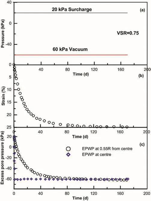
Fig.7.(a)Loading stages,(b)Time-strain plot,and(c)Excess pore water pressure(EPWP)dissipation plot of large-scale consolidometer test(US3)on undisturbed Ballina clay with scaled-down PVD under combined and vacuum preloadings.
Furthermore,the effect of vacuum pressure on coefficient of radial consolidation was investigated by conducting a large-scale consolidometer test(US3)with an undisturbed specimen subjected to a VSR of 0.75.The time-strain and the excess pore water dissipation trends are plotted together in Fig.7.The strain at the end of the primary consolidation for both of the large-scale samples(24.2%for US1 and 25.1%for US3)appeared as almost the same,resulting in almost identical volume compressibility coefficient(mv);but the coefficient of secondary compression(Cα)for US3 was relatively smaller(0.0005)than that of US1(0.0038).This is attributed to the accelerated radial drainage by vacuum consolidation,and in particular,the corresponding rapid initial settlement.To investigate the effects of vacuum pressure on the coefficients of radial consolidation and horizontal permeability in an undisturbed zone,a comparison between the two large-scale specimens US1 and US3 was performed without and with vacuum,respectively.
With the large samples(US1 and US3),the soil surrounding the mandrel is inevitably disturbed while installing the vertical drain,which results in a smear zone.To evaluate the extent of this smear zone,a graph showing the normalised reduction in water content((Wmax-W)/Wmax)and the ratio of the equivalent radius to the mandrel radius(r/rm)was plotted(Fig.8),whereWmaxis the maximum water content.The smear zone obtained from the larger samples(US1 and US3)was then compared with the in situ smear zone determined experimentally for single and multi-drain cases(Indraratna et al.,2015),following the experimental approach by Sathananthan and Indraratna(2006).It is found that the radius of the smear zone can be almost 5 times the radius of the mandrel(r/rm=5)for the large undisturbed sample and the field study(both single and multi-drain),but this ratio was double that obtained from the small laboratory specimens(r/rm=2.5).The smear zone obtained from the 350 mm-diameter specimen with a scaled down mandrel and drain is similar to the in situ smear zone,indicating that the use of large undisturbed samples is more appropriate to represent the field behaviour for this particular marine clay where natural partings and relics of marine environment(e.g.sea shells as shown in Fig.9)may influence the consolidation behaviour.
Based on the time-settlement curve,the coefficient of radial consolidation was determined using the following approaches:(1)the steepest tangent method(Vinod et al.,2010),(2)the square root method(Sridharan et al.,1996),and(3)the log-log method(Robinson,2009),while the coefficient of radial consolidation can also be determined based on the pore water pressure measurements(one at the centre and 0.55Rfrom the centre,representing average pore pressure,as shown in Fig.4b,whereRis the radius of base plate).Fig.6c-e and 7c show the dissipation of pore water pressure at different radii for both large and small samples with time,which confirmed that the rate of dissipation was much faster in small sample than that in large sample due to the scale effect.In addition,these dissipation plots at different radii were used to calculate the coefficient of radial consolidation for both samples.The following equation(Hansbo,1981)was used to calculate the coefficient of radial consolidation(Ch)based on pore water pressure measurements:

whereμis a characteristic parameter of the smear zone,andUpis the average degree of consolidation based on pore water pressure dissipation.

Table 2 Values of coefficient of radial consolidation(Ch).
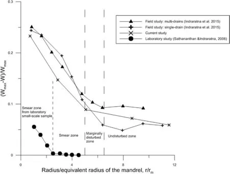
Fig.8.Variations of normalised reduction in the water content.
The average coefficients of radial consolidation determined from different approaches are tabulated in Table 2.The value obtained from the steepest tangent method is always the highest,whereas theChobtained from log-log method is always the lowest.With each method used to calculateCh,there is a slight decrease in the value ofChfor the large undisturbed sample(US1)compared to the small undisturbed sample(US2)tested in the Rowe cell.This can be attributed to two main factors:smear zone effect and scale effect.Two ratiosα1and α2can be defined for the corresponding effect,respectively.In this regard,α1is the ratio ofChof the smear zone to that of the undisturbed zone(US1),the value of which is unity in Rowe cell specimen(US2)due to the use of a pre-bored central drain.Similarly,α2is the ratio ofChof small undisturbed sample(US2)to that of the undisturbed zone of the large sample(US1),which represents the sample size effect.In order to determine these two factors,theChvalue in the undisturbed(i.e.nonsmear)zone was back-calculated using smear zone characteristics,as shown in Fig.8.The factor representing smear zone effect(α1)is found to be 0.75 whereas the factor representing the sample size effect(α2)is 0.8.In a practical sense,this implies that small or conventional undisturbed specimens may still be used for radial consolidation testing,but the value ofChdetermined may need to be adjusted accordingly on the basis of these two factors(α1and α2).Similarly,for large-scale sample with vacuum(US3),the coefficient of radial consolidation(Ch)in the smear zone is very similar to that of US1,which is probably due to th e use of the same mandrel(along with same shoe)and identical installation method adopted in the laboratory.However,the value ofChin the undisturbed zone for US3 is found to be significantly high(more than 35%)than that of US1(non-vacuum).

Fig.9.Soil sample showing the presence of large shells and natural partings.

Table 3 Consolidation parameters.
Table 3 shows the summary of consolidation parameters in terms of coefficient of horizontal permeability (kh),average compressibility (mv)and coefficient of radial consolidation (Ch)for all three samples.The compressibility parameter was calculated using the strain-time graph considering the EOP,as shown in Figs.6a and 7b.It is found that the large undisturbed sample(US1)is more compressible by at least 1.2 times larger than the small(traditional)undisturbed sample(US2).In other words,if a standard or conventional test specimen is used,then a correction factor of 1.2 may be applied to its compressibility(mv)to corroborate with actual field value which is more representative of the large(350 mm diameter)undisturbed specimen,and can relate the compressibility of the field more closely than that of small-scale specimens.The coefficients of compressibility for both of the large specimens(US1 and US3)are almost identical because both of the large-scale undisturbed specimens were extracted from the same depth and within close proximity to each other(5 m).
Furthermore,the coefficient of horizontal permeability for all three samples was calculated using the conventional analysis(kh=Chmvγw,where γwis the unit weight of water).As expected,it was found that the coefficient of horizontal permeability was greater for the largeun disturbed sample(US1)in comparison to the small undisturbed sample(US2)by almost 150%.This can be attributed to the greater extent of natural partings and imperfections existing within a large sample(see Fig.6)which can act as conduits to increase the hydraulic conductivity with the increasing sample size.Moreover,the coefficients of radial consolidation and horizontal permeability for US3(with vacuum)were found to be larger by 36%and 40%,respectively,compared with those of US1,which is solely due to the effect of vacuum application.The obvious differences when using large undisturbed samples over traditional small samples were discussed.Where possible,one may obtain better representation of the actual field consolidation behaviour through large undisturbed soil testing,especially where marine clay may have random coarse particles including gravels,shells and natural partings.
4.Conclusions
The following conclusions can be drawn based on the test results of this study:
(1)The consolidation behaviour in the large consolidometer with undisturbed test specimen(US1)may support the argument that some structural viscosity including creep effects may influence deformation even during the initial consolidation phase,hence an increased settlement.
(2)Two factors(α1andα2)representing smear effect and sample size effect which influence the coefficient of radial consolidation(Ch)were found to be 0.75 and 0.8,respectively.These factors can be used to correct theChvalue obtained from(conventional)undisturbed sample to account for the scale and smear effects,respectively.
(3)The extent of the smear zone obtained from the large undisturbed sample(US1)was comparable to the smear zone associated with the field study(i.e.5 times the equivalent diameter of the mandrel).
(4)The coefficients of radial consolidation and horizontal permeability were accelerated with the application of vacuum for large-scale undisturbed specimen and theChandkhvalues were found to increase by 36%and 40%,respectively,compared to the non-vacuum case.
(5)The coefficient of secondary consolidation for large-scale consolidometer is significantly reduced from 0.0038(for US1)to 0.0005(for US3)with the application of vacuum pressure.
(6)For predicting the behaviour of soft marine clay that is typically characterised by random coarse particles,shells or other relics of beach environment as well as by structural viscosity,a testing program undertaking large undisturbed samples seems more appropriate than traditional small specimen testing.
Conflicts of interest
We wish to confirm that there are no known conflicts of interest associated with this publication and there has been no significant financial support for this work that could have influenced its outcome.
Acknowledgements
The authors would like to thank the Australian Research Council(ARC)Centre of Excellence in Geotechnical Science and Engineering and the Centre for Geomechanics and Railway Engineering(CGRE)of University of Wollongong(UOW)for the financial support during the PhD of the first author.The authors wish to thank the technical staff of CGRE,especially Alan Grant,Cameron Neilson and Ritchie Mclean for their help during field visit and laboratory setup.
 Journal of Rock Mechanics and Geotechnical Engineering2018年6期
- Journal of Rock Mechanics and Geotechnical Engineering的其它文章
- Estimates for the local permeability of the Cobourg limestone
- Numerical modeling of deep-seated landslides interacting with man-made structures
- Influence of data analysis when exploiting DFN model representation in the application of rock mass classification systems
- Hydro-mechanical behavior of an argillaceous limestone considered as a potential host formation for radioactive waste disposal
- A simplified approach to assess seismic stability of tailings dams
- Finite element analyses of slope stability problems using non-associated plasticity