Modeling and Analysis of Spoke-Type Permanent Magnet Vernier Machine Based on Equivalent Magnetic Network Method
Shan Jiang, Guohai Liu, Wenxiang Zhao*, Liang Xu, and Qian Chen
(1. School of Electrical and Information Engineering, Jiangsu University, Zhenjiang 212013, China;2. Jiangsu Key Laboratory of Drive and Intelligent Control for Electric Vehicle, Zhenjiang 212013, China)
Abstract: In this paper, a new equivalent magnetic network(EMN) model is established for a spoke-type permanent magnet(PM) vernier(PMV) machine. Two different modeling methods are proposed for different parts of the PMV machine, considering that their magnetic field distributions are quite different. Hierarchical modeling method is proposed for the modeling of the rotor as the magnetic intensity of the rotor iron core presents gradient distribution along the radial direction. Mesh based reluctance network method is used for the modeling of flux modulation poles with irregular and unstable magnetic field distributions. Moreover, accurate PM leakage permeance calculation formulae are deduced to improve the simulation precision. The electromagnetic parameters, such as flux linkage,back electromagnetic force, electromagnetic torque and iron loss are predicted by the proposed EMN model. Finally, finite element analysis(FEA) and experimental results are given to verify the effectiveness of the proposed methods.
Keywords: Equivalent magnetic network(EMN), permanent magnet vernier(PMV) machine,hierarchical modeling method, mesh based reluctance network, finite element analysis(FEA).
1 Introduction
Permanent magnet(PM) vernier(PMV) machines have received increasing attention in wind power generation and direct-drive applications due to their inherently low speed and high torque characteristics[1-4].In order to further improve performance, a hybrid stator fault-tolerant(FT) PMV(FTPMV) machine was proposed in [5]. By adopting the new stator and spoke-type PMs,the performance of torque density, power factor and efficiency were improved. However, due to the multipole and spoke-type arrangement of the PMs, this machine suffers from serious PM flux leakage, tooth-tip flux leakage and complex flux distribution in fluxmodulation poles (FMPs), which greatly increases the modeling difficulty of equivalent magnetic network(EMN) methodology.
The PM flux leakage and tooth-tip flux leakage have significant influence on the simulation accuracy of the EMN model[6-12], but relevant research about PMV machines is limited[13-14]. In [13], an EMN model for a surface-mounted PMV machine was established to analyze the tooth-tip flux leakage. However, iron core saturation was ignored and the model can only be applied to no-load condition. In [14], a novel calculation method for air-gap permeance and tooth tip permeance was proposed. As this method cannot be applied to on-load condition and no-load condition at the same time, separate EMN models were built for the two working conditions, indicating that the modeling solutions for PMV machine were not mature enough.However, the EMN models of salient pole machine and spoke-type PM machine can be used as a reference, as the two types of machines and the spoke-type FTPMV machine have similar topology. In [6], EMN models were built for a mutually coupled linear switched reluctance machine and a surface mounted linear PM machine, in which piecewise linearization method was adopted to calculate the air-gap permeance by introducing overlapping coefficient of translator teeth and stator teeth. In [15] and [16], the machines have large slot opening width, and the magnetic lines in air gap region are scattering, thereby, the effective length and cross-sectional area of air-gap permeance will change with position. The air-gap regions were then divided into many segments to accurately calculate the effective lengths of flux paths so as to obtain higher accuracy. The modeling of pole shoe is also a key point,because the uneven flux distribution in pole shoe area may lead to local iron saturation[17-18]. The impact of local magnetic saturation on simulation accuracy was studied in [17], where results show that the errors under various areas of saturation regions were changed from-5% to 5%. In [18], a fitting method was used to model the saturation distribution on poles. By integrating the variables of geometry and rotor position, the fitting data was dependent on the pole pair position and phase current, making the calculation of flux linkage characteristics simpler and more accurate. As well, an EMN model for a spoke-type PM machine was investigated in [19], in which the modeling method for spoke-type PM and air-gap were introduced. However,the PM end leakage was omitted, even though this issue was an important topic in improving simulation precision.
For the spoke-type FTPMV machine, the flux density distribution of rotor iron core is uneven, which leads to different degrees of magnetic saturation.Additionally, the PM end leakage has a more significant effect on simulation precision. These issues are specific to the spoke-type FTPMV machine and the purpose of this paper is to solve such difficulties. Many different modeling methods are proposed for different parts of the FTPMV machine to better account for magnetic saturation, flux leakage and complex magnetic field distribution. An EMN model is built for this machine,and can be used for optimal design and performance prediction. In Section 2, the topology and design parameters of the FTPMV machine are briefly introduced. The modeling details are then presented in Section 3 and the solution process is given in Section 4.In Section 5, simulation results are given to make a comparison with that of finite element(FE) analysis(FEA)and experimental tests. Finally, conclusions are drawn in Section 6.
2 Machine specifications
The cross-sectional topology and photograph of the spoke-type FTPMV machine are shown in Fig.1(a) and Fig.1(b), respectively. The spoke-array PMs with flux concentration are inlaid in the rotor iron core. The armature teeth and FT teeth are alternately distributed in the circumferential direction, and the FMPs are formed by both the straight teeth and split-teeth. Single-layer concentrated winding design is adopted to reduce electromagnetic coupling of phases. The design parameters are listed in Table 1.
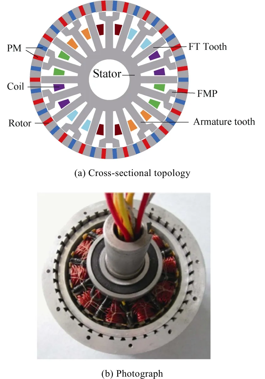
Fig.1 Spoke-type FTPMV machine
Fig.2(a) and Fig.2(b) show the magnetic field distributions of the spoke-type FTPMV machine when the rotor position (θ) are 0° and 90° (electrical angle),respectively. It can be seen that the flux distributions in air-gap and FMPs are irregular and complex, and will be influenced by rotor position and armature magnetomotive force. It seems that the flux line distribution of the spoke-type FTPMV machine is similar to that of the PMV machine proposed in [14], but the rotor flux distributions of the two machines have great differences. In addition, the PM end leakage in the spoke-array FTPMV machine is more sensitive to the main flux. It is necessary to establish accurate models for rotor and PM end leakage, and the main contribution of this paper is to propose corresponding solutions for these issues.
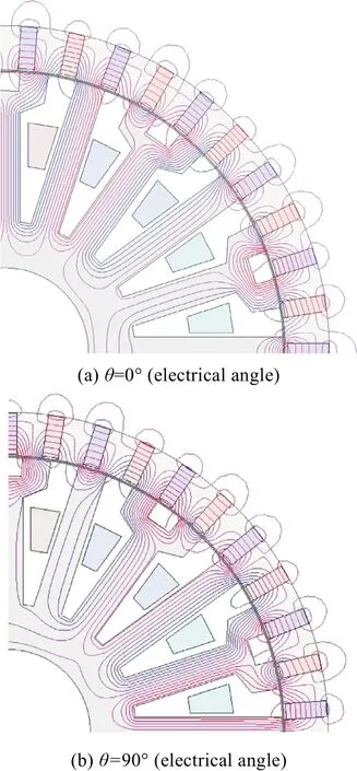
Fig.2 Magnetic flux distributions of the spoke-type FTPMV machine at different rotor positions
3 Modeling process
3.1 Rotor
Since the magnetic lines in the boundary region of PMs will form leakage circuits, the rotor iron core cannot be simply considered as a magnetic equipotential body. As shown in Fig.3, the magnetic intensity of the rotor iron presents gradient distribution along the radial direction. For simplicity, the PMs and the rotor iron core are divided into four layers along the radial direction,and the equivalent EMN model can thus be built as shown in Fig.4, where Gairis the external air gap leakage permeance, Gpmand Gironare the permeances of PM and iron core, respectively. The region shape of Gairis a semi annular, where its calculation formula can be expressed as:

where Ldis the stack length, r1, r2are the inner radius and outer radius of the semi annular, respectively. The region shapes of Gpmand Gironare regular rectangle, and their values can be obtained by a unified mathematical expression:

where G represents permeance, µ0is vacuum permeability, µris relative permeability, S and L are the effective sectional area and the effective length,respectively. Besides, the magnetomotive force of the spoke-type PM (Fpm) can be expressed as:

where Hcand lpmare the magnetic field intensity and excitation length of PM.
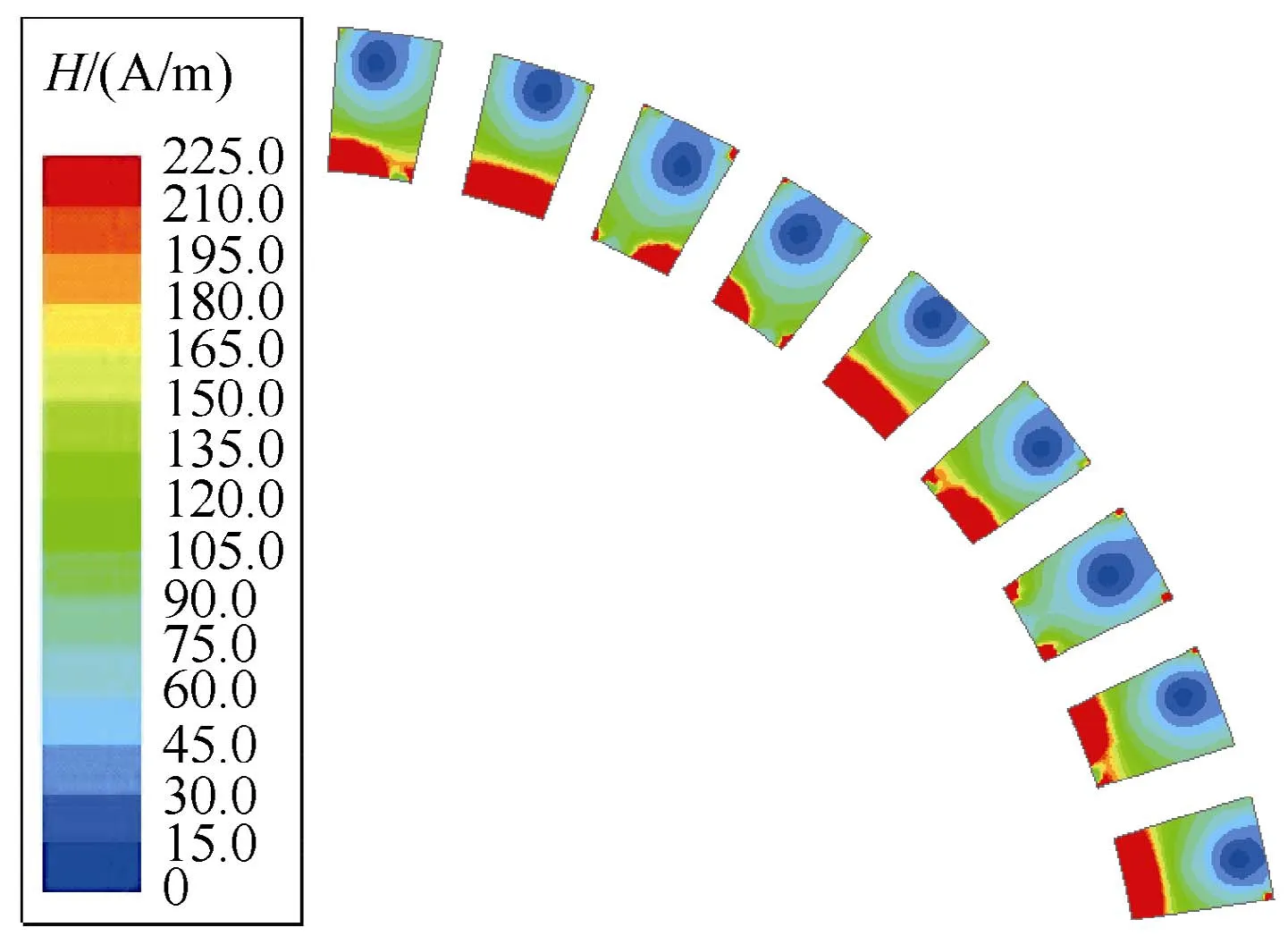
Fig.3 Magnetic intensity distribution nephogram of the rotor iron core
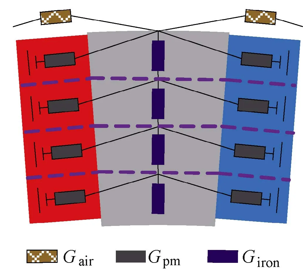
Fig.4 EMN model of rotor
3.2 Stator
The stator yokes, FT teeth and armature teeth are regular-shaped and the flux distributions of these regions are regular. Hence, their permeances can be calculated using (2). However, as the flux distributions in FMPs are irregular and unstable, they are hard to model using traditional magnetic circuit methods. As discussed in[20], using a mesh-based reluctance network taking the circumferential and radial branches into account, is an effective way to simulate the magnetic field distribution with different flux flow directions. This method can be employed for the modeling of FMPs. In Fig.5, the FMP is divided into four parts. Gxand Gyare the permeance components in the circumferential direction and the radial direction, respectively, and they can be calculated by

where a and b are the length and width of the FMP,respectively. The magnetomotive force of winding follows the current low, in which the displacement current is neglected and only the conduction current is considered. Hence the winding magnetomotive force(Fw)can be denoted as:

where Ncand i are the winding turns per coil and current,respectively.
The EMN model of stator is established as shown in Fig.6, where Gsy, Gat, Gft, Gps, and Gfmpare the permeances of stator yoke, armature tooth, FT tooth,armature tooth pole shoe and FMP, respectively.
3.3 Air-gap
According to the magnetic field boundary condition and minimum reluctance principle, the regions of air-gap permeances are rectangular and fan-shaped. These rectangular air-gap permeances should be calculated by(2), and these fan-shaped ones as shown in Fig.7 can be calculated by:

Fig.5 Mesh-based reluctance network

Fig.6 EMN model of stator
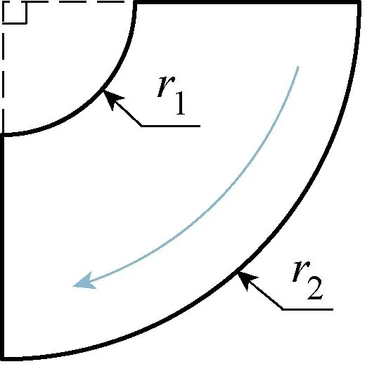
Fig.7 Fan-shaped air-gap region

where r1and r2are the inside and outside radius of the fan-shaped region, respectively.
Taking into account the PM flux leakage in the air-gap region, there are three relative positions between the rotor PM and FMP, namely the non-overlapping,the partial overlapping and the exact overlapping,corresponding to Fig.8(a)~Fig.8(c). The PM leakage flux paths of the three cases are depicted by blue lines with arrows.
In Fig.8(a), the flux paths are a series of arcs with differing radius. The corresponding region shape can be regarded as an isosceles triangle (the base length and height are wpmand wg1, respectively), and the effective length of flux path is approximately equal to the length of waist line. Letting Gnl1be the permeance of the area where the red line frame located, its calculation can be written as:
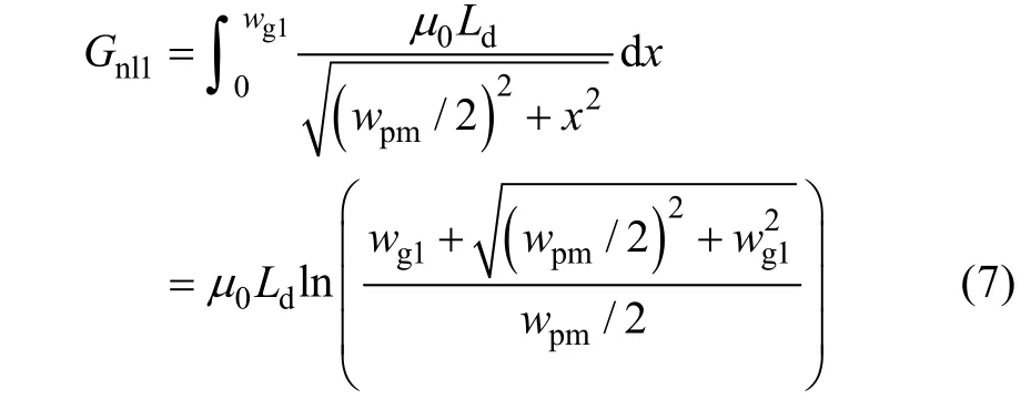
where wpmis the width of PM, wg1is the distance between PM and stator. The flux leakage permeance of the this case (Gnl) can hence be denoted by:

In Fig.8(b), the leakage permeance (Gpl) consists two parts: Gpl1and Gpl2, and their regions are marked with red wireframe. Gpl1and Gpl2are calculated by:
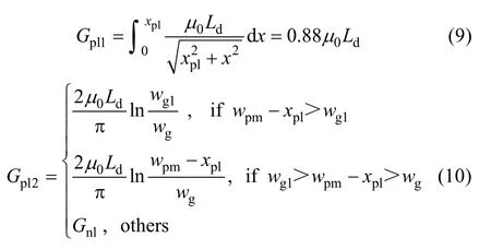
where xplis the non-overlapping length of PM and FMP,wgis air-gap width. Then Gplcan be gained by:

In Fig.8(c), the flux lines will flow through the FMP along the tangential direction, however, the magnetic potential drop can be neglected. Then the permeance of PM leakage flux (Gol) can be written as(12).
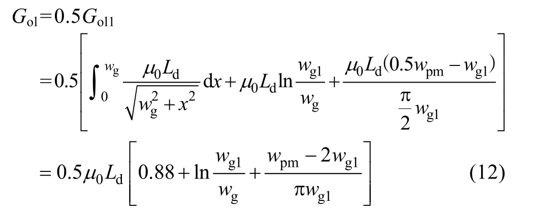
Finally, the complete EMN model for the spoketype FTPMV machine is built as shown in Fig.9.
4 Solution process
The solution process contains the following steps:

Fig.8 Relative positions between PM and FMP
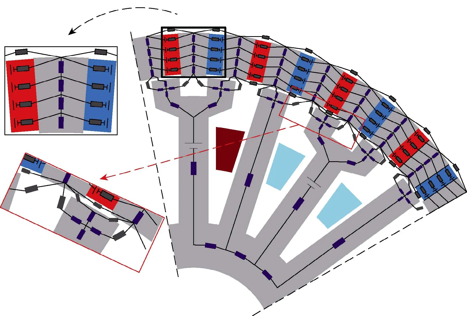
Fig.9 EMN model of the spoke-type FTPMV machine
Step 1: Set the initial position of rotor, simulation cycle and simulation step size.
Step 2: Calculate all of the permeances and magnetomotive forces, then establish nodal current equations.
The initial permeability should be first obtained to initialize the nonlinear permeances, and can be set as:

where μiniis the initial permeability, (HBH(1), BBH(1))and (HBH(2), BBH(2)) are the first point and the second point of the B-H curve. Meanwhile, the nodal current equations in matrix form can be listed using Kirchhoff’s current law:

It can be abbreviated as:

where G, F and Φ are the permeance matrix, nodal potential matrix and flux matrix, respectively.
Step 3: Solve nodal current equations.
In (15), F is the unknown variable, and can be solved using Matlab code:

The flux linkage (Φ ) and flux density (B) can be calculated by:

where i and j are the node numbers of the both ends of a permeance, S is the cross-sectional area where Φ pass through.
Step 4: Update the permeability of nonlinear material.
The permeability of nonlinear material should be updated by searching B-H curve:

where μnewis the updated permeability. In order to enhance iterative convergence, the newly obtained permeability should be reset using a correction factor:

where k represents iteration number, fcis the correction factor (0<fc<1) and it’s optimum value is 0.31.
Step 5: Update nodal current equations until the error requirement is met.
The μ(k)obtained in step 4 will be used to rebuilt the nodal current equations listed as (14), and the iterative process can be finalized when the following criterion is satisfied.

where ζ is the error tolerance, it’s value can be set as 1.0e-5.
Step 6: Change rotor position to obtain the complete simulation waveform of an electrical cycle.
The corresponding flowchart of the process is drawn in Fig.10.
5 Results validation
In order to validate the effectiveness of the proposed model, a two dimension FE model was built and experimental tests were carried out. The comparison results are given as follow.
5.1 Flux linkage and electromotive force
The flux linkages of every phase can be acquired by(17), and the back electromotive forces (back-EMFs)can be obtained by:

where E is the back-EMF, Ncis the number of turns per coil, and Φphis the flux linkage of armature tooth.

Fig.11 Comparison of flux linkage and back-EMF
The no-load flux linkage and back-EMF of phase A obtained by EMN model, FE model and experimental test are compared in Fig.11. The flux linkage amplitudes of EMN result and FE result are 51.79mWb and 51.71mWb, respectively (the error is less than 2%). The back-EMF amplitudes of EMN method, FEA and test are 72.0V, 71.5V and 70.0V, respectively. Meanwhile,harmonic content of back-EMF waveforms are analyzed in Fig.12. The content of the third harmonics have obvious errors, which is mainly caused by the machining error of prototype and the modeling error of the EMN model. However, it is found from Fig.12 that the magnitudes of the 3rd harmonics are far less than that of fundamental waves, and the errors in 3rd harmonic content do not significantly affect the main waveforms.Generally, the results are in good agreement with each other, which confirms the accuracy of the proposed model.
In addition, Fig.13 studies the effect of PM leakage permeance on main flux linkage. The amplitude error of the two waveforms is as high as 15%, hence, it is necessary to take PM end leakage into consideration for the spoke-type FTPMV machine. Moreover, flux linkage versus PM thickness is compared in Fig.14, it is seen that the increase rate of flux linkage becomes slow when the PM thickness is more than 3.5mm. The results of EMN method and FEA show slight deviation when the PM thickness is less than 3mm, which is caused by the simplification of the PM leakage circuits
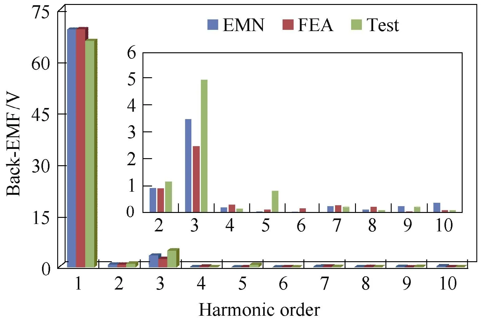
Fig.12 Harmonic analysis of back-EMF
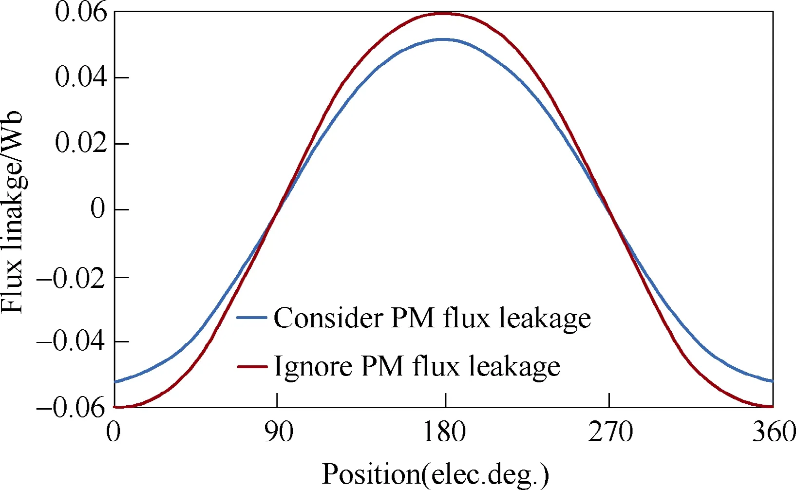
Fig.13 Effect of PM flux leakage on main flux
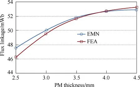
Fig.14 Flux linkage amplitude versus PM thickness
5.2 Air-gap flux density
The air-gap flux density (Bair) can be obtained by:

where ΔF and l are the magnetic potential drop and the effective length of air-gap flux lines. Hence, as shown in Fig.15, the air-gap flux density of position ① and position ② should be calculated by (23) and (24),respectively.
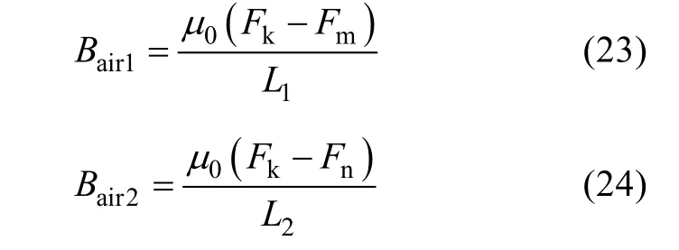
where Fk, Fmand Fnare nodal magnetic potentials, L1and L2are the effective lengths of the air-gap flux lines in position ① and position ②, respectively. The air-gap flux densities in other positions can also be obtained using the same method, and the simulation results of EMN model and FE model are compared in Fig.16. It can be seen that the waveforms in Fig.16 have very good agreement with each other.
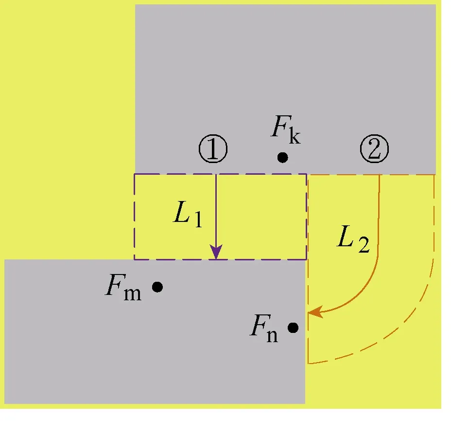
Fig.15 Calculation of air gap flux density
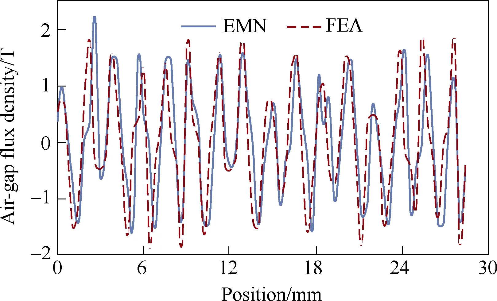
Fig.16 Air-gap flux density
5.3 Electromagnetic torque
The electromagnetic torque (T) is calculated by:

where Upvand Ipvare the peak value of back-EMF and current, respectively. θ is internal active power angle and Ω is the mechanical angular velocity of rotor. The simulation results of EMN model and FE model are compared with the experimental test (the current is 2.6A,rotor speed is 238r/min), as shown in Fig.17. The torque ripple of the test result is caused by cogging torque and mechanical friction, however, these issues do not have significant influence on the electromagnetic torque component. The mean values of the waveforms are 6.96N·m(EMN), 7.12N·m(FEA) and 7.07N·m(Test),respectively, the errors are less than 1.6%. Fig.18 shows the current-torque characteristic of the FTPMV machine,indicating the error between EMN result and FEA result is less than 5.7%.
5.4 Iron loss
Finally, iron loss is predicted using the discrete calculation method[20]:

where PFerepresents iron loss, f is frequency and B is flux density. kh, kcand keare the coefficients of hysteresis loss, eddy current loss and excess loss,respectively. The calculation results of iron loss versus current are compared in Fig.19. It is observed that the increasing tendencies of iron loss with current show good agreement, and the calculation error between EMN method and FEA is less than 7.7%, which further confirms the accuracy of the proposed model.

Fig.17 Electromagnetic torque

Fig.18 Electromagnetic torque versus current

Fig.19 Iron loss versus current
6 Conclusion
In this paper, a nonlinear EMN model is proposed for the performance analysis of a spoke-type FTPMV machine, in which a hierarchical modeling method and mesh-based reluctance network are employed for the modeling of rotor and FMPs, taking unequal magnetic potential distribution and complex flux distribution into account. PM flux leakage is also considered and the corresponding permeance calculations are deduced.Simulation results show that the proposed model has very high precision. Compared with FE model, the time requirement for the solution process of the EMN model is greatly reduced by approximately a factor of 24 (the EMN model only takes 5 minutes while the FE model takes about 2 hours), hence the EMN method presents great superiority in computational efficiency.
 Chinese Journal of Electrical Engineering2018年2期
- Chinese Journal of Electrical Engineering的其它文章
- Brushless Doubly-Fed Machines:Opportunities and Challenges
- Control and Applications of Direct Matrix Converters: A Review
- An Optimal Charging/Discharging Strategy for Smart Electrical Car Parks
- Two-Stage Transformerless Dual-Buck PV Grid-Connected Inverters with High Efficiency
- A New Active Gate Driver for MOSFET to Suppress Turn-Off Spike and Oscillation
- Dual-Coupled Robust Wireless Power Transfer Based on Parity-Time-symmetric Model
