Control and Applications of Direct Matrix Converters: A Review
Jianwei Zhang, Li Li, and David G. Dorrell
(1. Faculty of Engineering and IT, University of Technology Sydney, Sydney, Australia;2. Howard College Campus, University of KwaZulu-Natal, Durban, South Africa)
Abstract: In recent decades, the matrix converter (MC) has emerged as a promising AC/AC converter that performs the direct AC-to-AC conversion. Because of its attractive features such as compact volume, bidirectional power flow, controllable input power factor and sinusoidal waveforms,there has been an increase in MC related research work. Many control techniques have been proposed to control MCs and many potential applications have been investigated. This paper presents the state-of-the-art review in the recent development of control strategies and applications of MCs, starting with MC fundamentals. Some relevant simulation and experimental results are presented to show the performance of the corresponding controllers in specific applications. A wide range of control techniques and potential application fields are covered. Industrial products and modules are also discussed. Comparisons of different control strategies and different applications are summarized and presented. It is concluded that the MC is a promising converter and more research and industry interest is expected, particularly in AC motor drives and renewable energy microgrids.
Keywords: Matrix converter, AC/AC conversion, control strategies, model predictive control(MPC), motor drive, microgrid.
1 Introduction
AC-to-AC converters are widely used in various areas, including motor drives, renewable generation,grid interface, and unified power flow controllers(UPFCs). In industrial applications, AC-to-AC power conversion is usually accomplished by indirect converters. In these converters, AC power is first converted to DC by a rectifier, and then back to AC by an inverter. The rectifier and inverter are connected via a DC link with a bulky capacitor for charge storage. A typical example of this converter is the back-to-back converter as shown in Fig.1. The DC-link capacitor makes the volume bulky, reduces the lifetime of the device, increases the design complexity and decreases the system efficiency.Therefore, it is of benefit to remove the capacitor or propose a new converter topology. Some research work has addressed this issue. The AC-to-AC converter should have the following desirable features: sinusoidal input and output waveforms, low harmonic component,bidirectional power flow, small volume energy-storage devices, controllable power factor[1]. Matrix converters(MCs) appeared to be a possible solution since it can fulfill the above requirements.

Fig.1 Back-to-back converter topology
The concept of a direct MC appeared in the literature as early as the 1970s[2-3]. More extensive research started with the work of Venturini and Alesina in the 1980s[4-6]. An MC is composed of an array of controlled bidirectional switches that perform direct energy conversion without any energy storage elements in an intermediate link. A three-phase direct MC comprises nine bidirectional semiconductor switches arranged in a 3×3 matrix form to realize the direct AC-to-AC conversion. A three-phase direct MC is shown in Fig.2. In contrast to the conventional AC-DC-AC conversion, the MC does not require the DC-link capacitor, and completes the power conversion in one stage. The absence of the DC-link capacitor reduces the volume, enhances the efficiency, increases the lifetime and simplifies the control schemes. It only requires small filters to suppress the ripples generated by the switching actions[7]. The MC has received attention because of its advantages: sinusoidal input and output waveforms, controllable power factor,bidirectional power flow and the compact nature[4].
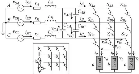
Fig.2 Three-phase direct MC circuit
MCs have attracted research interest, and many projects on the MC have been reported. This paper provides an overview of recent developments in control methods and potential application areas of MCs. Section 2 introduces some MC basics. Section 3 reviews the control techniques for MCs. Section 4 reviews the potential application fields and the industrial development. Section 5 concludes this paper.
2 Matrix converter basics
2.1 Bidirectional switches
Because of the required controlled bidirectional power flow, MC switches are bidirectional semiconductor devices. However, a single device that can control current and block the voltage in both directions is currently not commercially available[8]. Therefore, the bidirectional switches are usually formed from an appropriate connection of more devices. For MCs, typical bidirectional switching devices are implemented using various topologies: diode bridge arrangement[1,8-9];reverse block arrangement[8,10]; common emitter arrangement; and (d) common collector structure[1,8-9,11].These structures are shown in Fig.3. Here the insulated gate bipolar transistor (IBGT) is used as a representative of the controlled switch.
For MCs, (a) requires nine independent drive power supplies to build the MC circuit, i.e., one driver supply for each switch cell. The losses are relatively high since there are three devices in the conduction path. Moreover,it is difficult to control current direction through the switch. Fig.3(b) requires two controlled switches. The diodes that provide reverse blocking capability are removed. Six independent drive supplies are required to build the MC circuit. Fig.3(c) and Fig.3(d) facilitate the bidirectional control. These are good for solving the four-quadrant commutation problem. In the common emitter structure, nine independent drivers are needed to control the IGBTs, while in the common collector configuration only six drivers are required[12]. In addition,the configurations in Fig.3(c) and Fig.3(d) can provide an inherent auxiliary commutating current path, which enables the implementation of advanced commutation techniques[13].
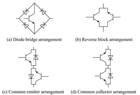
Fig.3 Topologies for bidirectional switches
It should be pointed out that the development of semiconductor device technology influences the properties (switching frequency, voltage blocking capability, voltage and power ratings, etc.) of the converters. Fast power switches are desirable as the volume of filters may be reduced by increasing the frequency[14]. The development of novel semiconductor devices such as SiC (silicon carbide) or GaN (gallium nitride) switches can potentially improve the converter performance.
2.2 MC switch matrix
There are nine bidirectional semiconductor switches in a three-phase direct MC, as shown in Fig.2. These nine switches form a 3×3 matrix and allow 27 valid switch states. The relationship between the inputs and outputs of the MC can be established as
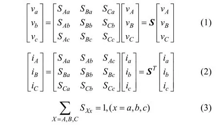
where S (transpose ST) is the switch matrix and vA,B,Care the output phase voltages. Other variables are denoted in Fig.2. Elements SXxin the switch matrix can be assigned either a value of one (for the ON state) or zero (for the OFF state). The output voltage and input current can be controlled by controlling the switch matrix. The constraint (3) is used to exclude the invalid switch states that short-circuit the input sources or open-circuit the loads. These invalid switch states can cause detrimental overvoltage and overcurrent.
2.3 MC space vectors
The three-phase system variables can be expressed by space vectors by using the transformation:

where x1,2,3are the variables in the three-phase system;α=ej(2π/3)and α2=ej(4π/3)and xsis the corresponding space vector after the transformation.
In the MC, 27 space vectors are formed by 27 switch combinations. These space vectors can be classified into three groups: active, zero and rotating vectors. Only active and zero vectors can be usefully applied in space vector modulation (SVM) to synthesize the desired vectors. The detailed descriptions of these space vectors can be found in [7, 15-16].
3 Control strategies of MCs
Many modulation and control strategies have been proposed for MCs[17]. Generally, the modulation strategies can be classified into: 1) scalar techniques (e.g., Venturini method[18]); 2) PWM methods (carrier based and SVM)[7];and 3) other control strategies (such as hysteresis current control[19-20], predictive control[21], sliding mode control(SMC)[22], direct torque control(DTC)[23], fuzzy method[24]and neural networks[25]). Some of these methods have been recently investigated. In addition, proportionalintegral (PI) and proportional-resonant (PR) controllers based on SVM have been investigated for the MC[26-27].
3.1 Venturini method
The Venturini method is a direct modulation technique. Based on the direct transfer function approach, the switch timings are directly calculated from input voltages and target output voltages. Computation of these timings is cumbersome for practical implementation. Another drawback of this method is that the voltage transfer ratio cannot exceed 0.5[28]. To improve the voltage transfer ratio, the optimized Venturini method was proposed. In this method, the voltage transfer ratio is improved from 0.5 to 0.866 by the third harmonic injection method[12]. A description of the Venturini method can be found in [17-18].
3.2 SVM
Pulse width modulation (PWM) techniques for MCs include carrier based and SVM modulation approaches. In the carrier-based modulation, the input power factor can be regulated by using the offset voltage and changing the slope of the carrier[29-30]. The SVM is a more popular method and it has the potential to make the best use of input voltage to reduce the number of commutations, to control the input power factor and to provide better power quality[28,31]. Based on the space vector representation, the SVM combines the adjacent two vectors and zero state vectors to generate the desired reference[32]. SVM can generalize the modulation issue of MCs. There are direct and indirect SVMs for MCs.Direct SVM provides a better understanding of the operation and modulation process due to the absence of a fictitious DC link[12]. The indirect SVM is easier to implement.
The synthesis of the output voltage and input current vectors are based on duty cycles. The duty cycles for direct SVM are obtained using [16]:

where 0≤θρ≤π/3 is the angular difference between the desired output(input) space vector and its corresponding right-hand adjacent vector. tx1, tx2and ty1, ty2are working times for the selected vectors and Tsis the cycle period.For m and n (m, n = 1, 2, 3, 4, 5, 6), these represent the mth output voltage vector sector and the nth input current vector sector.
The corresponding times of tγα, tδα, tγβ, tδβand t0in the indirect SVM are obtained using[15]:

where 0≤θR(θI)≤π/3 is the angle between the desired output (input) space vector and the right-hand adjacent vector; m = mi×mvis the modulation index.
Indirect conversion is capable of controlling output frequency, amplitude and input current phase displacement[7,33]. This method can decouple the modulation of the virtual rectifier stage and the virtual inverter stage, thus making it possible to combine different modulation strategies of two stages[34]. This is illustrated in Fig.4. In addition, the indirect conversion scheme facilitates the analysis of input voltage unbalance[35].
Fig.5 shows the experimental results for indirect SVM of MC. Fig.5(a) shows the MC input voltage and current and Fig.5(b) shows the output currents. As can be seen, the SVM controlled MC can generate sinusoidal waveforms. However, open-loop SVM becomes ineffective in controlling the output currents to the desired values when the load is unknown.
Based on SVM, the closed-loop controllers such as PI, PR and SMC have been investigated for the MC[26-27].These controllers are simple and independent of the system model because of current loops. In [26], a modified PI controller with current feedforward was proposed to reduce the steady-state error when tracking sinusoidal references. A PR controller was also investigated to improve the tracking performance[27].

Fig.4 Illustration of overall modulation with virtual rectifier, inverter and DC link

Fig.5 Experimental results of SVM
3.3 Hysteresis band(HB) control
The HB current controller features inherent current limiting capability, robustness, no modulation stage, and simple implementation, in addition to the excellent dynamic and tracking performance. The HB control has been mainly constrained to the voltage source inverter(VSI), and active research on this includes constant switching frequency control, online computation of bands, and multi-band hysteresis control. In [36], a comparative study for fixed-band and sinusoidal-band hysteresis current controllers (F-HB and S-HB) was carried out for VSIs; however, the used hysteresis bands are impractical, and the comparison needs further evaluation for various band widths and sampling frequencies. In [19], both F-HB and S-HB are investigated and compared for an MC based permanent magnet synchronous motor (PMSM) drive. The F-HB control of MC is shown in Fig.6 for a single-phase current control[19].
In the F-HB control of an MC, the maximum or minimum voltage is applied to increase or decrease the currents as explained by:
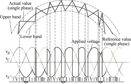
Fig.6 HB for three-phase direct MC
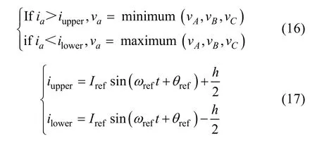
where iref= Irefsin(ωreft + θref) is the reference current for iaand h is the hysteresis band width. iupperand ilowerare the upper and lower bands. vA,B,Care MC input voltages. It is worth noting that the MC offers more flexibility compared to the VSI since it offers more voltage choices. In general, there are three levels of voltages available in the MC rather than two in the VSI.This flexibility benefits the implementation of multi-band HB control.
Fig.7 shows the MC output current and voltage waveforms regulated by the HB control to drive a PMSM. The HB control is a very simple control method for the MC and has very light computational burden.Therefore, it is more practical to implement compared to other control methods for MCs. In addition to F-HB,S-HB was investigated, and comparative results are obtained in [19].
3.4 DTC
The DTC is especially relevant when the MC is used to drive an AC motor[23,37-39]. This controller has been widely used in high-performance motor drives because of fast torque dynamic response and robustness.As its name implies, DTC controls the torque and flux directly. It is a simple yet powerful control technique for motor drives, and it offers various benefits including fast torque response, robustness, no coordinate transformations (angle detection), no modulation stage,and no current controllers required[40-42]. DTC does not require any other motor parameters except for the stator resistance; this enhances the robustness of the controller.DTC can also operate in sensorless mode-torque control mode. These contribute to the fast development of DTC,in both research and industry, for the applications of high-performance drives[43]. DTC for MCs has attracted interest. A DTC control structure for a motor drive is shown in Fig.8[39].

Fig.7 Experimental results of HB controlled MC-PMSM
In DTC, the stator flux and torque are controlled by selecting the appropriate voltage vector. The available voltage vectors can be obtained using the method described in Section II. Fig.9 shows the influence of different voltage vectors on the stator flux and torque. In this figure, F↑, T↓ indicates that the flux and torque will be increased and decreased respectively if that voltage vector is selected[39]. DTC is a widely researched topic for MCs, and results can be readily found in the literature, e.g. [41].
3.5 Model predictive control(MPC)
Another popular control tool for the power electronic converters including MCs is MPC[44]. With the development of microprocessors, MPC has become an increasingly researched topic in recent decades[45].This controller can provide flexibility to control different variables, and the constraints can be considered in the controller. In the literature, many studies on the predictive control of MCs have been reported[46-47].
MPC utilizes the system model to predict the future behavior and selects the optimum switch action based on the user-defined cost function. Depending on the control objectives (which can be voltage, current or others),corresponding predictive models can be developed.
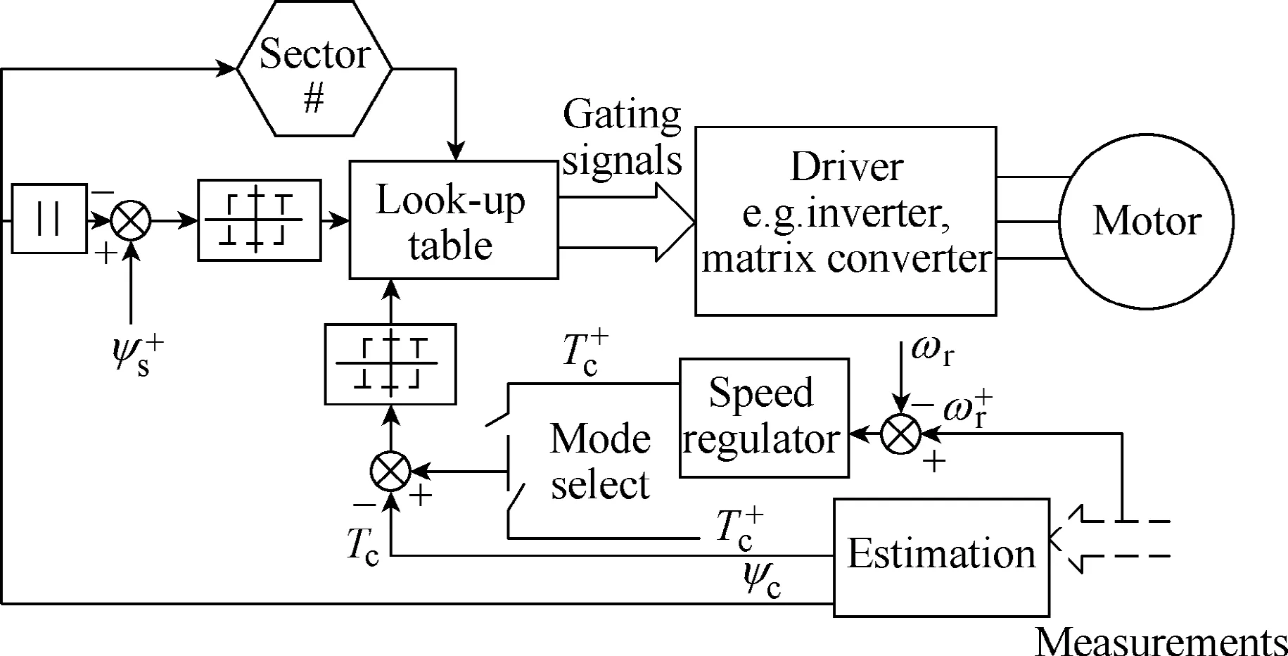
Fig.8 Block diagram of DTC for a motor drive with inverter or MC
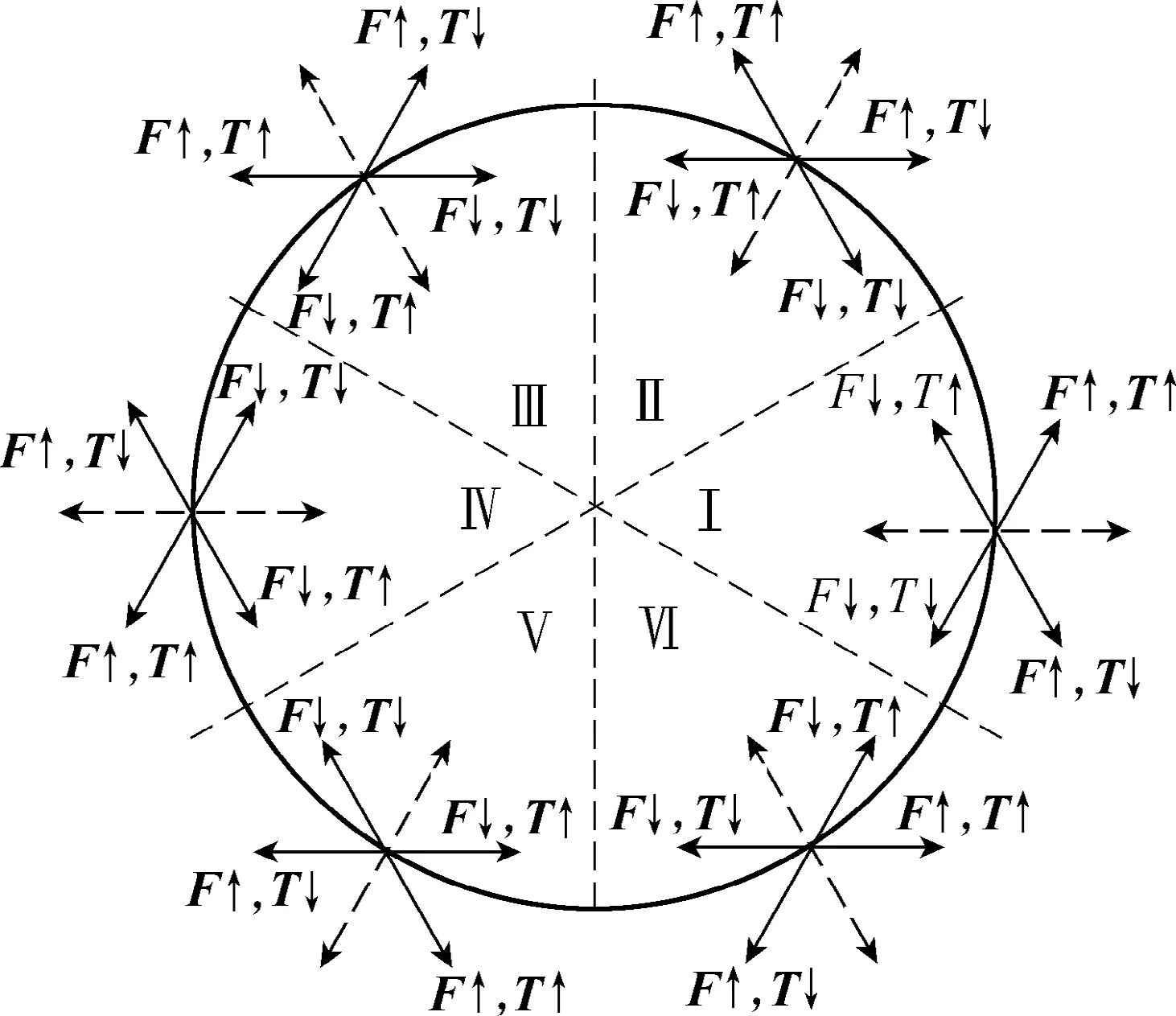
Fig.9 DTC illustration diagram with the MC voltage vectors
3.5.1 Predictive voltage control
In predictive voltage control, the main control objective is the sinusoidal output voltage. To achieve this, an LC filter is utilized and the predictive model is established based on the model of this filter. In [48], a predictive voltage control strategy of MC was proposed for application to renewable distributed generation and microgrid. The following cost function is used to optimize the switch selection:

Fig.10 shows the experimental results of predictive voltage control under the condition of load disconnection.As observed, the output voltage can be regulated effectively.
3.5.2 Predictive current control
In the predictive current control, the main control objective is the sinusoidal output current. The cost function to evaluate the switch states becomes

where i*represents the reference signal and iprepresents the predicted values. In order to include the input power factor regulation, the overall cost function is modified to

Here λ is the weighting factor which specifies the relative importance of the control objective. The weighting factor is usually obtained by time-consuming empirical methods through a complex process, which is a significant drawback of MPC.

Fig.10 Experimental results of the output voltage and current responses to load disconnection
Fig.11 shows the experimental result of MC output currents controlled by the predictive current control. The output currents are controlled effectively to track the references.
In order to address the issue of complex weighting factor design, the sequential MPC(SMPC) was proposed[49,50]. In the SMPC, g1and g2are evaluated individually in sequential order. The switch states are evaluated in g1first, and two most suitable switch states that render the minimum values of g1are selected. Then these two switch states are evaluated in g2to select the final switch state to be applied. g1is evaluated first because the output current regulation is more important than the input power factor control. Fig.12 shows the experimental result of MC output currents controlled by the SMPC. Similar results compared to the standard MPC are achieved, but the complex weighting factor design is eliminated. The SMPC also helps reduce the computational burden.
3.6 SMC
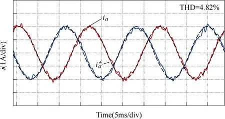
Fig.11 Experimental results of load currents regulated by MPC

Fig.12 Experimental results of load currents regulated by SMPC
The SMC control strategy has been designed for the three-phase MC[51]. SMC can provide advantages such as stability against large disturbances, fast dynamic response and suitability for nonlinear systems[52]. It has been proven to have improved robustness in providing fast transient responses over a wide range of operating conditions[53]. The sliding mode based direct power control was proposed for an MC to control the power flow of a transmission line[22]. This scheme enables the real-time selection of appropriate state space vectors to regulate the input and output variables. It also exhibits robust behavior and immunity against the nonlinearity of power system. The results for the SMC of MC can be found in [22, 51].
The performance comparison of some control strategies for MCs is shown in Table 1. Among these controllers, the investigation of the hysteresis controller for MCs remains underexplored. At present, the Venturini method is not attracting much attention. However, the research on SVM, DTC and predictive control are still very active. The predictive control appears as a promising control tool because of its simplicity, good performance and flexibility to include additional control objectives and system constraints. The derivatives of predictive control for power converters and drives can include predictive current control, predictive voltage control, predictive power control and predictive torque control.
4 Potential application areas of MCs
The MCs can be applied in a wide range of areas,and it is particularly suitable for the applications that require a compact volume, low weight and reliability[54].However, only a very low percentage of industry applications has been achieved so far[55]. Even so, there are already some commercially available MC products and modules. Some examples of these products are the Yaskawa FSDrive-MX1S series, U1000, AC7, Eupec ECONOMAC FM35R12KE3ENG and Fuji FRENIC-Mx.Table 2 summarizes the information of the MC related commercial products. In this table, only the maximum available rating is listed for voltage and capacity,although the products with lower ratings are available.The power ratings are not converted in order to keep consistency with the data in the technical specifications.In addition to the MC products, there are many commercially available power switch modules that can be used to construct an MC. As observed from Table 2,most MC manufacturers have oriented the target application to motor drives.
In the literature, the motor drive is the most widely investigated application area of MCs[25,56-58]. The MC has been proposed for the applications such as UPFCs[59-62], mobile utility power supplies[63-65], wind turbines[66-69]and microgrids[15,48,70,71]. The summarized information and features of these application areas are provided in Table 3. These application areas are described below.

Table 1 Performance comparison of some MC control techniques

Table 2 Information of some MC products and modules

Table 3 Summarized information of investigated applications areas of MC
4.1 AC motor drives
The area in which the MC can be most potentially exploited both in industry and academia is the AC motor drive. Nowadays, the motor drive applications are dominated by voltage source converters. For a high-inertia system that requires dynamic braking, the VSI-based drive system usually requires a rectifier stage to supply the DC voltage and the braking chopper to absorb the kinetic energy generated from the motor deceleration. These will make the system bulkier,decrease the efficiency and increase the complexity.Because of the capability of bidirectional power flow, an MC-based drive system does not require the braking chopper that is essential in the VSI-based drive to absorb the energy during motor deceleration or reverse rotation if a back-to-back inverter system is not used.Therefore, the efficiency is improved, and maintenance is alleviated. Fig.13 illustrates the structure of an AC motor drive with VSI or MC. In the literature, many control methods have been investigated for the MC-fed motor drives. These include DTC, field-oriented control(FOC) and MPC. The tested motor types include induction motor and PMSM.
Fig.14 shows the experimental results for a PMSM driven by an MC[19]. As seen in Fig.14, the rotor speed can track the target speed effectively with the MC-based drive system. The input power factor can be readily regulated, which is an advantage of the MC-based drive.This is hard to achieve with a VSI-fed drive.
4.2 UPFC
The MC has been investigated for the UPFC in flexible alternating current transmission systems[59-62].
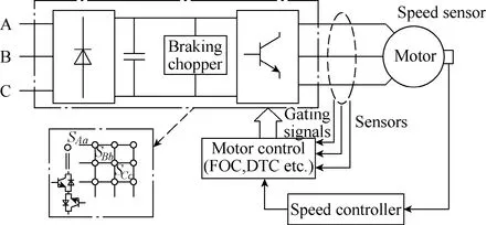
Fig.13 Comparison of VSI and MC based motor drive system
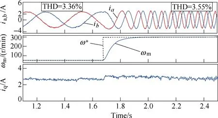
Fig.14 Experimental PMSM stator currents, rotor speed and q-axis component current responses to command speed step change from 50 to 300r/min when TL = 1.5N∙m
The traditional UPFC employs a back-to-back converter that can fulfill the AC-to-AC conversion indirectly.The traditional UPFC combines a static synchronous compensator(STATCOM, shunt controller) and a static synchronous series compensator(SSSC, series controller).These two controllers are connected via a DC capacitor link. A UPFC can improve the capacity of a transmission system. However, the capacitor in the traditional UPFC produces losses, increases the weight and volume,reduces equipment lifetime and requires DC voltage control. In contrast, there is no bulky DC-link capacitor needed in an MC-based UPFC(MC-UPFC), as shown in Fig.15. This structure has advantages such as compact configuration, less weight, bidirectional power flow,high efficiency, controllable input power factor, and longer lifetime. Some research work on MC-UPFC has been carried out to test the performance, and some good results have been reported in the literature[61,71].

Fig.15 MC-UPFC in a double-line transmission system
In [71], the decoupling controller is designed for MC-UPFC, and the controllable region is analyzed.Fig.16 shows the regulated active and reactive power in a transmission line. The active and reactive power can be controlled to track the prescribed reference effectively. The flexibility in power control can enhance the transmission capacity of a transmission system.
4.3 Renewable energy generation
In terms of renewable power generation, the wind turbine has become a popular topic[66-69]. In the application of wind turbines, the MC has been employed to regulate the performance of a wind generator and achieve the maximum power extraction, thus better efficiency. Wind power generation is regulated to produce electricity for a wide range of wind speeds. In a conventional scheme, a very large DC-link capacitor almost separates the control of the generator and grid-side.In contrast, the generator and grid-side quantities are controlled simultaneously in the MC based scheme.Therefore, a better cooperative control can be achieved.Grid-side reactive power can be effectively regulated,which is desirable in a grid-connected wind turbine. The MC based scheme is particularly suitable for the offshore wind generation because of low weight, compact size,high efficiency and reduced transportation cost. Many control strategies have been studied in this area.
4.4 Utility power supply
Another potential application area that has been investigated is the mobile power supply[63-65]. In this application, an MC is integrated with a variable speed diesel generator to serve as a utility supply. There are growing interests in utilizing the static power converters to supply high-performance AC power in uninterrupted power supply, programmable AC source and mobile supply unit. An MC based mobile AC ground supply unit was proposed for aircraft servicing[65]. The use of this unit removes the auxiliary power unit on the aircraft that is supplied by burning jet fuel. Therefore, the noise,air pollution, and maintenance are reduced, which is beneficial to the aircraft. This application is an interesting field which can attract attention from the industry and academia.
4.5 Microgrid
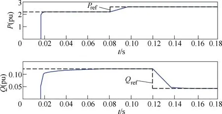
Fig.16 Simulated response of the sending-end power to the step change in active and reactive power

Fig.17 Experimental results of output voltages and currents for the unbalanced load test
MCs can also be applied in microgrids for interfacing the distributed renewable generations into the utility grid[48,70,72]. However, this application area remains underexplored. In terms of microgrid applications, there are two operation modes, i.e., islanded and grid-connected mode. In each mode, the main control objectives are different. This is a significant application that needs more research attention and further investigation.
The application of MC in the islanded microgrid with distributed generation is investigated in [48].Various tests including unbalanced load, nonlinear load and input intermittent disturbance are carried out. Fig.17 shows the experimental results of the unbalanced load test in an MC-based islanded microgrid. In addition, the work on the grid-connected MC is presented in [70]. It is expected that more research interests will be attracted in this field.
5 Conclusions
An MC is a direct AC/AC converter and it has attracted interest. Compared with traditional AC/DC/AC converters, MCs have many benefits because of the absence of large energy storage elements. Many research works and projects have been reported recently. This paper reviews the state-of-the-art development of MCs regarding the control strategies and application areas.Many control strategies and applications are covered and compared. It is concluded that the HB controller is a very simple control method for MCs and it is especially suitable for practical MC-fed motor drives. MPC is a promising control technique that is flexible in controlling power converters including MCs. It is believed that the MC is a promising converter and more research and industry interest are expected, particularly in AC motor drives and renewable energy microgrids.
 Chinese Journal of Electrical Engineering2018年2期
- Chinese Journal of Electrical Engineering的其它文章
- Brushless Doubly-Fed Machines:Opportunities and Challenges
- An Optimal Charging/Discharging Strategy for Smart Electrical Car Parks
- Two-Stage Transformerless Dual-Buck PV Grid-Connected Inverters with High Efficiency
- A New Active Gate Driver for MOSFET to Suppress Turn-Off Spike and Oscillation
- Dual-Coupled Robust Wireless Power Transfer Based on Parity-Time-symmetric Model
- A Modular DC/DC Photovoltic Generation System for HVDC Grid Connection
