Dual-Coupled Robust Wireless Power Transfer Based on Parity-Time-symmetric Model
(School of Electric Power, South China University of Technology, Guangzhou 510640, China)
Abstract: The characteristics of the wireless power transfer(WPT) system vary under different transfer distances. As distance increases, efficiency drops off sharply, limiting the wider use of WPT technology. In order to mitigate this problem, this paper proposes a novel dual-coupled WPT system,where both electric-coupled mechanism and magnetic-coupled mechanism are utilized to enhance the transfer efficiency. Furthermore, a Parity-Time(PT)-symmetric circuit is utilized to realize robustness of the system. The coupled-mode model of the system is established and the expressions of operating frequency, transfer efficiency and output power are deduced. Analysis results indicate that in the unbroken PT-symmetric state, compared with single-coupled systems, the proposed system can keep constant performance within a longer distance; in broken PT-symmetric state, the proposed system has higher transfer efficiency. Simulated results and comparative results are in accordance with the theoretical analysis. Within 1.4m, this scheme can transfer power with constant efficiency of 77% and constant output power of 70W.
Keywords: Wireless power transfer(WPT), parity-time(PT)-symmetric, coupled-mode model,robust.
1 Introduction
Since the idea of wireless power transfer(WPT)was put forward by Tesla[1], this technology has experienced a long process of development. There are two main categories of WPT: magnetic-coupled power transfer and electric-coupled power transfer. Until now, a slew of real-world applications use the former technology to achieve wireless charging, such as implantable medical devices[2-3], portable equipment[4-5]and electric vehicle[6-7]. The latter technology can be applied to dynamic devices and occasions limited by space, such as synchronous machines[8]and internal isolations[9]. However, most of these traditional WPT systems only work efficiently at a specific transfer distance, and the efficiency drops off sharply with increasing distance. In 2007, scientists from MIT successfully lit a 60W bulb wirelessly at a medium distance based on the principle of magnetic-coupled resonance[10]. In their experiment, the transfer efficiency is about 70% when the transfer distance is 1.5 m. However, when the distance is extended to 2m,the efficiency drops to 45%. Takehiro Imura et.al from the University of Tokyo developed a system for charging wirelessly for electric vehicles[11]. At the distance of 20cm, the transfer efficiency is as high as 97%, whereas it drops to lower than 20% when the distance is extended to 40cm. In order to mitigate this problem, Ref.[12] presented an inductive and capacitive combined WPT system, in which the efficiency is enhanced to some extent. Nevertheless,this system is still not robust against variations in distance. The concept of Parity-Time(PT)-symmetry was first raised in optics[13], and now it has been widely used in this field. Ref.[14] introduced this concept into WPT field and proposed a robust WPT system. This system uses an operational amplifier to attain a PT-symmetric mode, realizes efficiency-constant power transfer within 70 cm, and provides milliwatt power to the load. Ref.[15] raised a single-wire electric-coupled power transfer system using PT-symmetric model, whereas the efficiency is relatively low due to the non-negligible internal resistances.
Inspired by above references, in this paper, a dual-coupled robust WPT system based on PT-symmetric model is presented, where both electric-coupled mechanism and magnetic-coupled mechanism are utilized. In this scheme, a half-bridge inverter with feedback is used to achieve PT-symmetric mode, which can realize high-power and high-efficiency robust power transfer. Based on state space average model,coupled-mode model of the system is deduced.Characteristics such as operating frequency, transfer efficiency and output power are analyzed according to the model. The analysis results indicate that when the modal fields satisfy the unbroken PT-symmetric arrangement, the transfer efficiency and output power of the system stay constant versus different values of transfer distance. The system performance in the broken PT-symmetric arrangement is also studied.Compared with other single-coupled systems, the proposed system can keep unbroken PT-symmetric state within a longer distance, and can have higher transfer efficiency in the broken PT-symmetric state.A circuit model has been built and the simulated results verify the theoretical analysis.
2 System structure and modeling
Generally, traditional magnetic-coupled power transfer systems make use of inductive coils to transfer power via the magnetic field, and traditional electric-coupled power transfer systems make use of mental plates to transfer power via the electric field.The difference is that the proposed system utilizes two kinds of mechanisms simultaneously, and the structure is shown in Fig.1.
Fig.2 illustrates the equivalent circuit of the system,consisting of a half-bridge inverter with current feedback,internal resistances R1and R2, coil inductances L1and L2, compensation capacitances C1and C2, equivalent coupling capacitance Csresulting from metal plates,mutual inductance M resulting from coils, and equivalent load resistance RL. Besides, i1and i2denote the currents through L1and L2, respectively; u1and u2denote the voltages on C1and C2, respectively. Note that the coupling polarity of L1and L2should be opposite, otherwise two coupling mechanisms will cancel out each other.
State-space equations of the system are listed first, as shown in (1).
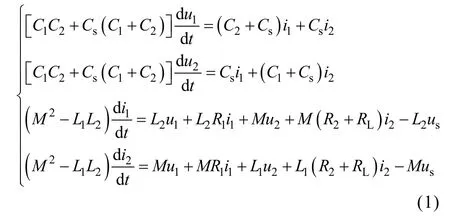
Here, usdenotes the equivalent input voltage provided by source module, and it depends on the current waveform of i1due to the feedback. According to Ref.[16], the expression of usis shown in (2), where Vinrepresents the voltage of DC source in the inverter.

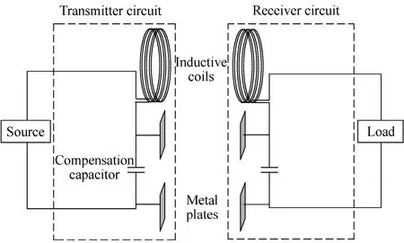
Fig.1 Structure of the dual-coupled robust WPT system
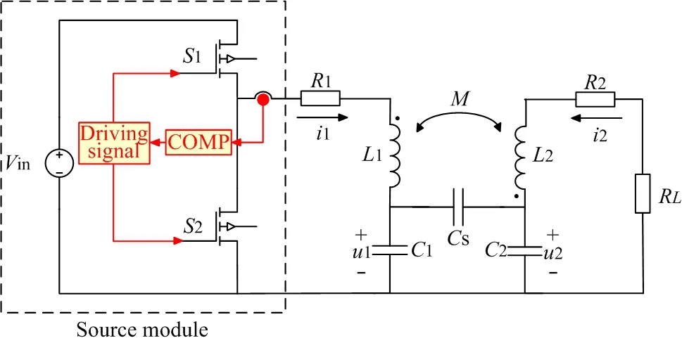
Fig.2 Equivalent circuit of the system
By defining complex variables
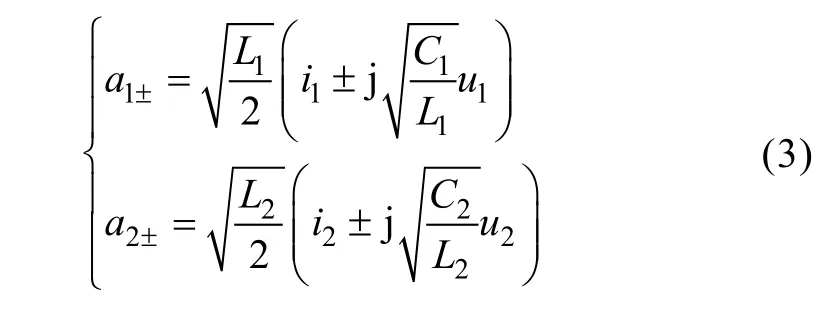
we can obtain the expressions of in, unand their derivatives represented by an±, as shown in (4), where n=1,2.
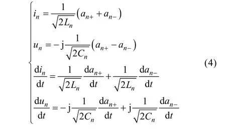
To substitute (3)~(4) into (1) and ignore the relations between an+and, the results as (5) can be obtained.

Here, the following variable substitutions have been defined and implemented: natural angular frequenciesnatural loss ratesload rate γL= RL/(2L2),inductive coupling rateand capacitive coupling rate
To deduce the coupled-mode model, following assumptions are established:
(1) Generally, in WPT systems, the natural angular frequencies of two resonant cavities are almost equal to each other such that we define ω1=ω2=ω0.
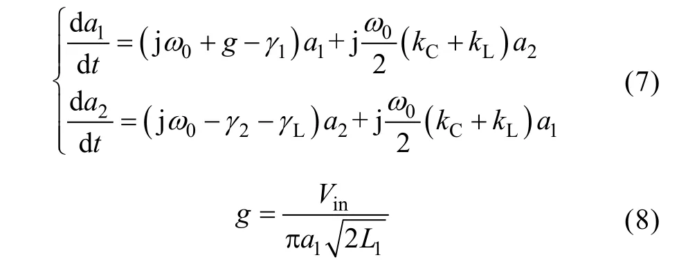
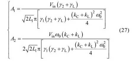
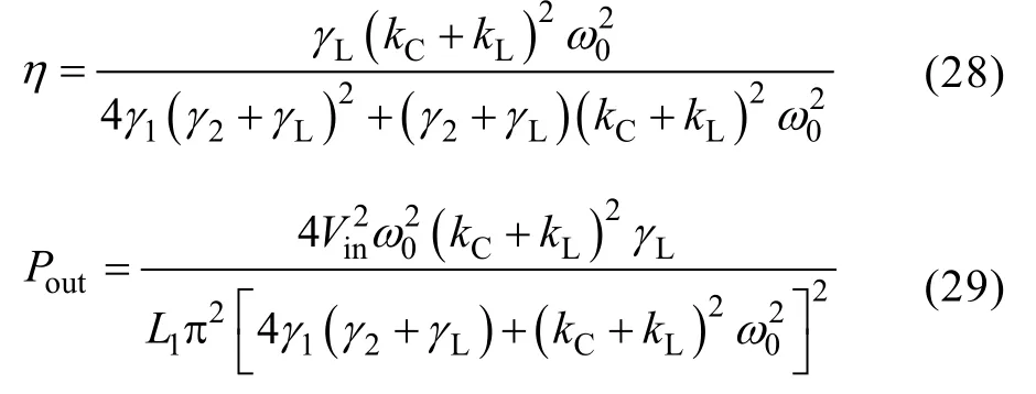
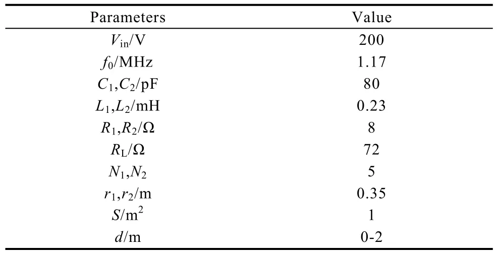
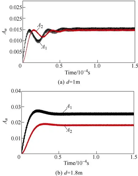
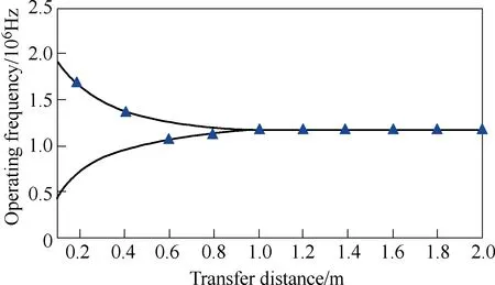
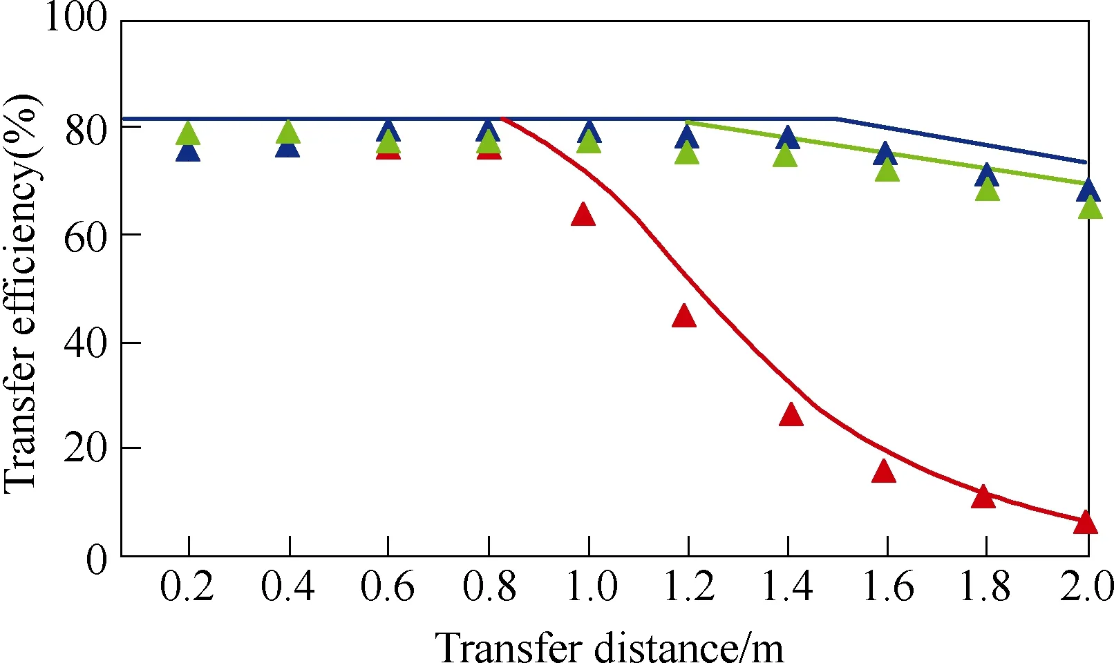
(2) Assume that Cs< Then the coupled-mode model of the system can be provided by neglecting relatively small items in (5),as presented in (6). As a+and a-are equivalent, for simplification,only a1+and a2+are chosen here and denoted by a1and a2, respectively. In (6), the coupling item contains the sum of kLand kC, which reveals that two kinds of coupling mechanisms overlap with each other. To specify the action mechanism of the system,(6) is rewritten, and the results are shown in (7),where the gain rate g can be expressed by (8). According to Ref [18], for a long-range system,the steady solutions of (7) can be defined as [a1a2]T=[A1A2]Tejωt. Here, A1and A2are the amplitudes of a1and a2, respectively; ω is operating angular frequency of the system. The characteristic equation can be deduced, as presented by (9). Then the expression of ω can be presented by(10). Based on (10), we consider that the modal solutions have two cases as follows. Case 1: kC+kL≥2(γ2+γL)/ω0. In this case, the system gets the unbroken PT-symmetric state, and we have Here, and sinθ=(g–γ1+γ2+γL)/[(kC+kL)ω0]. It is important to note that θ only exists under the condition where kC+kL≥(g-γ1+γ2+γL)/ω0. Expression (8) indicates that, resulting from the current feedback mechanism, the value of g is influenced by a1. When the system just starts, the value of a1is approximately equal to zero. This makes the value of g high enough so that the real part of the exponent in (11) is greater than zero, that is [g–(γ1+γ2+γL)]/2>0. Thus the amplitudes of a1and a2begin to increase. On the other hand, the increase of a1results in the decrease of g,which slows the modal growth. Once g is smaller than the threshold value and makes the system satisfy the condition [g–(γ1+γ2+γL)]/2<0, the amplitudes of a1and a2begin to decrease, which leads to the increase of g again. The above process repeats, and finally the system would reach a stable state, where the value of g keeps constant: To substitute (13) into (11), the modal solutions can be rewritten, as shown in (14). Here, Case 2: kC+kL<2(γ2+γL)/ω0. In this case, the system gets the broken PT-symmetric state, and we have Here, Differently from case 1, in this case, θ only exists under the condition where kC+kL<(g-γ1+γ2+γL)/ω0.According to (16), the threshold value of g has also been changed, and the condition of modal growth is presented in (17). Similarly, when the condition in (17) is satisfied, the amplitudes of a1and a2will increase, otherwise they will undergo a damping. After a dynamic process, the stabilization will be reached, where the value of g can be expressed by (18). To substitute (18) into (16), the modal solutions can be rewritten, as shown in (19).According to the above analysis, the proposed system can reach steady state under arbitrary values of the sum of coupling rates (kC+kL). Based on the analysis in section 3, when the system satisfies the condition of case 1, the expression of operating angular frequency ω is:As the coupling rates are included in (20), the value of ω is not a constant and varies with the value of(kC+kL). Besides, in this case, a bifurcation appears.Without any tuning, the system adjusts its operating angular frequency to one of two branches under different coupling condition, so that the stable state in(14) can be reached. To substitute (13) and (20) into (7), the result as(21) can be obtained. Since |a1|2and |a2|2represent the energy stored in the transmitting resonant circuit and receiving resonant circuit respectively, (21) reveals that the system has realized a complete energy transfer. From (8), (13) and (21), the result as (22) can be deduced. Then the transfer efficiency and output power of the system can be calculated by (23) and (24),respectively. According to (23)~(24), in this region, both η and Poutkeep constant under different values of kCand kL. On the other hand, when the system satisfies the condition of case 2, the expression of operating angular frequency ω is: It indicates that in this case, the aforementioned bifurcation of ω disappears. The value of ω remains unchanged with the variation of (kC+kL), and equals to the natural angular frequency of the resonant circuit. To substitute (18) and (25) into (7), the result as(26) can be obtained. Equation (26) reveals that, in this region, only part of the energy stored in the transmitting resonant circuit is transferred to the receiving resonant circuit,and the degree of the transfer is influenced by the value of (kC+kL). From (8), (18) and (26), the result as (27) can be obtained. Then the transfer efficiency and output power of the system can be calculated by (28) and (29),respectively. It is important to note that the coupling rate of the dual-coupled system is the sum of the coupling rates of two single-coupled systems, which has a favorable impact on the transfer characteristics: in case 1, the transfer distance of constant-characteristics has been extended since the critical coupling rate increases (the smaller coupling rate corresponds to the larger transfer distance); furthermore, in case 2, the transfer efficiency has also been improved due to the superposition of coupling mechanisms. There are many kinds of structure for inductive coils and metal plates. In this section, space spiral coils and parallel plates are adopted without loss of generality, and the mutual inductance and plate equivalent capacitance can be calculated by (30) and(31)[19-20]. Here, μ is air permeability, d is transfer distance,N1and r1are the number of turns and radius of the transmitting coil, and N2and r2are the number of turns and radius of the receiving coil, respectively. Here, ε is air permittivity, and S is effective coupling area of the plates. For a determined system, the value of kLdepends on M, and the value of kCdepends on Cs. based on (30)and (31), since the values of M and Csdepend on d,different values of d determine different values of kLand kC. According to the analysis in section 3 and section 4, is the critical condition of two cases. Here, we define a critical distance dcr, and when d=dcr, the condition in(32) can be satisfied. To verify the theoretical analysis, a circuit simulation model in PSIM is built and the main parameters used for simulated analysis are presented in Table 1. Based on (3) and the data of simulated currents and voltages, the curves of Ancan be gotten, as shown in Fig.3. Here, the black solid lines denote A1and the red solid lines denote A2. When d=1m, the system is under the condition of case 1, A1and A2are nearly equal to each other when the system reaches the stable state. When d=1.8m, the system is under the condition of case 2, two amplitudes are not the same anymore,and A2is much smaller than A1. Table 1 Main parameters for simulations Fig.3 Curves of An versus time By substituting the values of parameters in Tab.1 into (20) and (25), the theoretical curve of the operating frequency can be obtained, presented by the black solid lines in Fig.4. The blue triangles denote the simulated data. When d<dcr, a bifurcation can be observed and the value of operating frequency switches between the two branches (for example,the simulated result is consistent with the branch of high frequency when d is 0.2m or 0.4m, and consistent with the branch of low frequency when d is 0.6m or 0.8m). When d>dcr, the bifurcation disappears and the operating frequency equals to ω0. In Fig.5, the transfer efficiencies of three kinds of WPT systems are compared. The blue solid line and triangles denote the theoretical curve and simulated data of the proposed dual-coupled system, while the green and red marks denote those of robust electric-coupled power transfer system and robust magnetic-coupled power transfer system, respectively. Here, the robust electric-coupled power transfer system is realized by setting the value of kLto zero, such that only the electric-coupled mechanism works. Similarly, the robust magnetic-coupled power transfer system is realized by setting the value of kCto zero, such that only the magnetic-coupled mechanism works. Besides,all the theoretical curves are obtained by substituting the values of parameters in Table into (23) and (28).The theoretical values of dcrof the three systems are 1.48m, 1.18m and 0.83m and the simulated values are about 1.4m, 1.2m and 0.8m respectively. It indicates that the proposed system has the longer critical transfer distance. When d<dcr, all the systems keep nearly 77% of the efficiency constantly, while the theoretical value is 81.8%. Furthermore, when d>dcr,all three systems have a descrease in efficiency, while the efficiency of the proposed system is clearly higher than the other two single-coupled systems. Specially,when the distance is 2 m, the efficiency of the robust electric-coupled systems has decreased to about 60%,the efficiey of the robust magnetic-coupled systems has decreased to about 5%(little power can be transferred), while the proposed system maintains about 70% of the efficiency. Fig.4 Operating frequency versus transfer distance Fig.5 Transfer efficiency of the three kinds of WPT system versus transfer distance Fig.6 Output power versus transfer distance In Fig.6, the black solid line is the theoretical curve of the output power based on (24) and (29), and the blue triangles are the simulated data. The results show that when d<dcr, the system provides nearly 70W to the load constantly, while the theoretical value is 75.3W. As well, when d>dcr, an increase of the output power can be observed. The above simulated results and comparative results are in accordance with the theoretical analysis. This paper proposes a dual-coupled robust WPT system based on PT-symmetric model, where two kinds of coupling mechanisms are used to enhance the transfer efficiency and a PT-symmetric circuit is used to achieve system robustness. The coupled-mode model is built to describe the system, based on which the system performance is studied. Compared with single-coupled systems, this scheme can realize constant-characteristics power transfer within a longer distance. As well, the transfer efficiency is also enhanced. Simulated results verify the theoretical analysis.
3 Action mechanism of the system


4 Analysis on transfer characteristics


5 Simulation and discussion



6 Conclusion
 Chinese Journal of Electrical Engineering2018年2期
- Chinese Journal of Electrical Engineering的其它文章
- Brushless Doubly-Fed Machines:Opportunities and Challenges
- Control and Applications of Direct Matrix Converters: A Review
- An Optimal Charging/Discharging Strategy for Smart Electrical Car Parks
- Two-Stage Transformerless Dual-Buck PV Grid-Connected Inverters with High Efficiency
- A New Active Gate Driver for MOSFET to Suppress Turn-Off Spike and Oscillation
- A Modular DC/DC Photovoltic Generation System for HVDC Grid Connection
