Brushless Doubly-Fed Machines:Opportunities and Challenges
P
(1. School of Electrical Engineering, Southeast University, Nanjing 210096, China;2. Warwick Manufacturing Group, University of Warwick, Coventry, UK;3. Faculty of Engineering and Environment, Northumbria University, Newcastle upon Tyne, UK)
Abstract: The brushless doubly-fed machine(BDFM) is a family of multiport electric machines with two ac electrical ports and a common mechanical port. Different from the conventional singly-fed machines whose synchronous speed is solely determined by a single supply frequency and the actual pole pair number, the BDFM has two supply frequencies and two different pole pair numbers to control the rotor speed. By the two accessible electrical ports, all BDFMs are endowed with more degrees of freedom for speed and power control, inherent fault-tolerant capability and high reliability. The BDFM in its broad sense has been extensively investigated as a promising alternative to the conventional slip-ring doubly-fed induction machine(DFIM) during the past decades, for both limited and wide speed range applications. This paper presents a new theoretical framework of the BDFM within which all topological variants can be closely linked by the similarities in working principle. The individualities of each machine topology are presented first, followed by the commonalities such as the modeling techniques, modes of operation, design considerations and control strategies. The challenges are identified and highlighted based on recent developments and possible opportunities are predicted considering the unique nature of this special AC machine type.
Keywords: Brushless doubly-fed machine, multiport electric machine, modeling techniques,modes of operation, design considerations, control strategies.
1 Introduction
Doubly-fed machines(DFMs), including the traditional slip-ring doubly-fed induction machine(DFIM)and various brushless versions, pertain to the emerging multiport electrical machines and play an indispensable role in efficient and flexible energy conversion, transfer and/or recovery. Recent research trends in this broad area have highlighted the distinct advantages of brushless doubly-fed machines(BDFMs) over the slip-ring DFIM and even conventional singly-fed machines in some aspects, such as the enhanced reliability due to the robust brushless rotor configuration and multiple modes of operation, the low-cost fractionally-rated power electronics converter for limited speed range applications,flexible control of active and reactive power, crowbarless low voltage ride-through(LVRT) grid integration capability, etc., showing their promising prospects in variable speed drive and generation systems. It is worth noting that by the BDFM term the authors do not refer to the specific construction with a nested-loop or reluctance rotor, but rather to a family of brushless AC machines of the following common features:
·There are two relatively independent AC electrical ports [i.e., power winding(PW) and control winding(CW)] with the ability to handle bidirectional power flow on the stator.
·There is a single physical mechanical port(the shaft)to input or output mechanical power.
·Doubly-fed synchronous operation can be realized.
·Asynchronous operation is possible if one of the two electrical ports is short-circuited.
A broad body of work has been published during the past years and this paper aims at providing an up-to-date reference of the published work and the systematic background knowledge by developing a new theoretical framework of the BDFM in its broad sense to help research and industrial communities keep track of the recent progress in this fast-growing area.
To the best of the authors' knowledge, the first attempt to categorize the DFMs was made in 2001[1].The frequency behavior, power flow, modeling and control aspects of the DFIM and its brushless counterparts were mainly focused on, and a brief comparison in terms of ease of manufacture, converter rating and control complexity was conducted in this work to foresee the commercial future of different topologies. A historical evolution of cascading two DFIMs into the modern brushless DFIM (BDFIM) is detailed in [2]. The control methods for the brushless doubly-fed reluctance machine (BDFRM) have been reviewed in [3]. Starting with a concise description of the origin and development of BDFMs with nested-loop and reluctance rotors, the material presented in [4] places more emphasis on the structural diversity of rotor topologies.
This paper is concerned with the available designs,operating modes and applications of the BDFM in a totally different manner from, and in many respects it augments in content, the reviews hitherto published on the subject[1-4]. The work is also closely relevant to research on brushless electrically-excited synchronous machines(EESMs) and multiphase machines. It is organized as follows. Section 2 deals with the proposed classification and key definitions related to BDFMs.Section 3 overviews the basic topologies, working principles and electromagnetic performances of a wide variety of BDFMs reported in the literature. Section 4 describes the modeling issues, whereas the modes of operation and the main target applications are summarized in Section 5. In Sections 6 and 7, the considerations in design of BDFMs(torque ripples and time-harmonic distortion, iron saturation effects, core losses, vibration and acoustic noise) and control strategies, mainly including the mostly studied field oriented control(FOC) and direct control methods, are presented. Concluding remarks and directions for further research are given in Section 8.
2 Classification and key definitions
All BDFMs can be conceptually conceived as the outgrowths of removing the brush gear of the DFIM,which can be generally accomplished either by PM excitation, cascading or modulation. The PM excitation reduces the number of ac electrical ports and as such is excluded from the scope of BDFMs. Cascading means maintaining the basic DFIM configuration with an extra power device to transfer power onto the rotor winding in a contactless fashion, while the modulation represents a sophisticated utilization of short-circuited coils, variable reluctance or flux guides to provide magnetic cross-coupling between two distributed stator windings of different pole pairs[5]. Either way, the stator windings—PW and CW, are indirectly coupled through the rotor action, as illustrated in Fig.1.
With respect to the cascading type, the contactless power transfer from a static power supply to the rotor winding can be achieved by cascading another DFIM(within the same frame or not) or using a rotary transformer (RT). Consequently, the cascaded DFIM(CDFIM)[6]and the DFIM with RT(DFIM-RT)[7]come to realization.
As for the modulation type, the rotor structure is of utmost importance because it provides the only means to indirectly couple the stator windings through the airgap field modulation behavior. To this extent, the rotor can be designed with short-circuited coils, salient-pole blocks or flux-barrier segments. The short-circuited coils give birth to the nested-loop rotor BDFIM and multilayer wound rotor BDFIM[8], while the salient-pole blocks and flux-barrier segments bring about the BDFRM[9], whose rotor usually takes three different forms in practice, namely, the simple salient pole, the multi-layer flux-barrier, and the axially laminated design.A number of hybrid rotors can be further derived from these basic rotor constructions. For instance, the hybrid rotor in [10] is virtually a combination of short-circuited coils and flux-barrier segments. The magnetic circuit optimization is realized by introducing flux-barrier blocks into the BDFIM with a nested-loop rotor[11]. A detailed classification of the BDFM is shown in Fig.2.
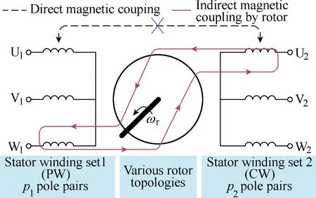
Fig.1 The schematic diagram of the BDFM in its broad sense
Thanks to this classification based on operating principles, previous research on all BDFMs can be reorganized in a unified way. Though differing a lot in terms of structure(i.e., the structural diversity), BDFM topologies of the same type considered in Section 1 share nearly the same vector models, modes of operation,design aspects and control strategies, as will be discussed in detail in Sections 3~7. The key definitions and angular velocity relationships are introduced here first in order to characterize the operation of all BDFMs in consistent terminologies though some of them have already been proposed for the BDFIM with a nested-loop rotor[12].
There are in total three synchronous speeds in BDFMs, i.e., the PW-synchronous speed(ωp/pp), the CW-synchronous speed(ωc/pc) and the doubly-fed synchronous speed (ωs), which can be expressed as:

where ωpand ωcare angular frequencies of the 2pp-pole PW and 2pc-pole CW, respectively, and peqdenotes the number of equivalent pole pairs. The latter can either be the sum or the absolute difference of ppand pc. The cascading (or modulation) type is termed as sum cascading (or sum modulation) only if peq=pp+pc, where the torques produced by the ppand pcpole pair magnetic fields are co-acting. On the contrary, the cascading (or modulation) type is termed as difference cascading (or difference modulation) if peq=|pp-pc|, where these torques are counter-acting. Therefore, the sum cascading(modulation) is usually used for high torque and low speed applications whereas the difference cascading(modulation) is more suitable for high speed operation[8].In the modulation version (sum or difference modulation),ppand pcshould be different to avoid direct magnetic interaction between the stator windings. However, for the cascading type, pp≠pcis only required for the difference cascading, otherwise the machine turns out to be a tandem induction machine (IM) and (1) is no longer applicable. The BDFM works in doubly-fed synchronous mode, i.e., synchronous operation, only if the rotor speed is given by (1), otherwise, it is in asynchronous operation.
In a special case when the CW is fed by DC, the BDFM degrades into a brushless EESM, whose dc field winding and AC armature windings are located on the same stator core and indirectly coupled by a passive rotor, and the corresponding doubly-fed synchronous speed is then termed as natural synchronous speed,which is:

Fig.2 The classification of BDFMs

The BDFM works in natural synchronous operation only if it runs at the natural synchronous speed formulated by (2). Below this speed, it is operated in the sub-natural-synchronous mode, and if above, it enters the super-natural-synchronous mode. Similarly, the BDFM is in super-PW-synchronous mode if the rotor speed exceeds the PW-synchronous speed. The synchronous speeds and associated operating modes are summarized in Fig.3 for convenience.
3 Basic topologies and fundamental principles
3.1 Cascading type
This BDFM type can be explained straightforwardly by the electrical equivalent circuit (EEC). As illustrated in Fig.4, the DFIM has directly-coupled stator and rotor windings and is therefore equivalent to a two-port network. The two-port structure will remain by connecting an additional two-port network to the DFIM in cascade, while eliminating the brushes and slip rings in the process. The two-port network can be another DFIM or a transformer. It is obvious that there is no direct coupling between the two stator windings of the cascading type due to the spatial separation.

Fig.3 Synchronous speeds and operating modes of BDFMs
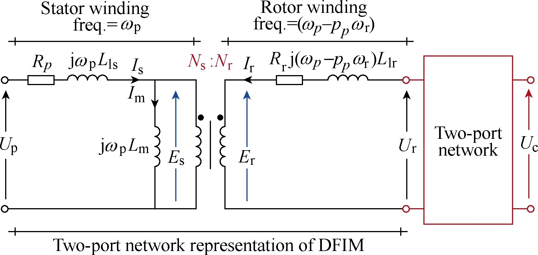
Fig.4 Operating principle of the cascading type from the point of view of electric circuit theory
Once DC components, such as DC excitation windings or uncontrollable rectifiers appear in the cascade system, the whole system will become singly-fed because one of the two electrical ports loses the capability for bidirectional power flow. Typical examples are the classical multi-stage synchronous generator with brushless excitation and the recently proposed synchronous machine(SM) with capacitive power transfer[13]. The brushless system realized by cascading a DFIM with an inverted SM via a rotating power converter also turns out to be a singly-fed one,though it is also sometimes termed as BDFIM in the literature [14].
3.1.1 CDFIM
The CDFIM is the ancestor of BDFMs and can be dated back to the cascade concept in poly-phase traction motors[6]. A typical cascading system comprised of two DFIMs is schematically depicted in Fig.5(a), whereby the two IMs are arranged with the shaft mechanically coupled and slip-rings of the primary motor connected to the stator windings of the secondary motor. The stator windings of the primary motor are directly fed from the main supply, while the slip-rings of the secondary motor are short-circuited through the starting or regulating resistances, i.e., the rheostats. To avoid the unreliable slip-rings, the cascade connection between the two rotors (instead of rotor-stator) was proposed, resulting in the well-recognized configuration of CDFIM shown in Fig.5(b)[15]. Note that, to achieve the sum cascading, the stator and rotor windings in Fig.5(a) should be connected in the same phase sequence (i.e., a-A, b-B,c-C), but for the CDFIM in Fig.5(b), the two rotor windings should be connected with the reversed phase sequence (i.e., a-c, b-b, c-a). The synchronous torque characteristic produced in doubly-fed operating mode is quite similar to the conventional SM, as will be shown in Section 5. However, apart from the desired synchronous torque, there are some non-zero parasitic asynchronous torque components caused by the rotor resistance (corresponding to the d-q axes cross-coupling phenomena) that increase the control complexity especially near the PW-synchronous speed. The pole-pair combination has been recommended to meet the pp≥pcconstraint for better performance in terms of power flow, converter size, system efficiency and machine utilization[16].
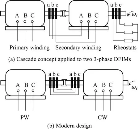
Fig.5 The CDFIM evolution
Though it is theoretically feasible to cascade any two DFIMs to form a CDFIM, it is still unclear as to what kind of combination will be the optimal for the cascading construction. Sometimes, the two stators are enclosed in the same frame and the interconnected rotors are replaced by a crossover squirrel-cage rotor to form the single-frame CDFIM. To reduce the envelope volume and improve the mechanical integrity of the CDFIM, an intuitive idea of integrating a small IM into the internal vacancy of the DFIM brings about the dual-stator BDFIM(DS-BDFIM) design[17]. A non-magnetic rotor support layer is always required to eliminate the direct coupling between the two magnetic fields traveling in the inner and outer airgaps.
3.1.2 DFIM-RT
The DFIM-RT is a DFIM cascaded by a RT, which enables contactless inductive power transfer to the rotor winding from a static power converter, as illustrated in Fig.6[7]. It can be regarded as a special case of the CDFIM when the number of pole pair of CW is set to null. In contrast to the CDFIM, the control side produces no parasitic asynchronous torque due to the permanent alignment of the rotor and the stator windings of the RT.Generally, the option of using three single-phase transformers is preferable to avoid unbalanced magnetizing flux. Both radial and axial airgaps can be adopted, except that the latter introduces axial force on the bearing due to magnetic attraction.
3.2 Modulation type
Unlike the cascaded version, the BDFM modulation type relies on the asynchronous modulation behavior of the specially-designed rotors. The operating principles can be explained by the general airgap field modulation theory[5]. The primitive magnetizing magnetomotive force (MMF) established by one of the stator windings,is asynchronously modulated by the rotor to generate a full spectrum of MMF harmonics, among which one principal harmonic couples the complementary stator winding to produce effective flux and electromotive force in generating mode or electro-magnetic torque by injecting current in motoring mode. Despite the apparent differences in rotor constructions, the modulated MMFs have a similar spectrum distribution, and the effective harmonic of Nr-pc(for the sum cascading or modulation)or Nr+pc(for the difference cascading or modulation)pole pairs takes a relatively large proportion in coupling with the complementary stator winding, where Nris the number of rotor nests, rotor salient poles or multi-barrier segments. Since the PW and CW are accommodated in the same stator core, special care should be taken in the design process to avoid potential direct coupling between them, which is closely related to the pole pair combination, number of parallel paths, the winding type and winding connection[18-19].

Fig.6 The DFIM-RT[7]
3.2.1 BDFIM
Research on pole changing and pole amplitude modulation winding created the idea of superseding the redundant rotor windings of self-cascading two DFIMs within a single magnetic circuit with a simple and robust nested-loop winding or multiphase double-layer winding[8]. To date, a number of rotor winding structures have been proposed, such as the nested-loop winding with a common ring, isolated nested-loop winding,nested-loop winding with two common rings[20], seriesloop winding[21]and multi-phase double-layer winding with equal or unequal turn coils[22], as shown in Fig.7.Although all of them can perform the aforementioned field modulation and achieve cross-coupling between the PW and CW, they exhibit distinct differences in rotor resistance and leakage inductance levels, which significantly impact the electromagnetic performance(the degree of cross-coupling between PW and CW,torque density, efficiency, LVRT capability, etc.) and control properties as elaborated in [23-25]. Notice that the well-known nested-loop rotor which was originally invented for ease of manufacture, turns out to suffer from unequal rotor current distribution-the outer loop carries larger current and withstands higher temperature,leading to a high inter-bar current if uninsulated bars like die-cast squirrel-cage rotor for the IM is adopted[26].In this respect, the series-loop winding and the multiphase double-layer winding with equal or unequal turn coils may outweigh the nested-loop one by equalizing the current distribution in conductors, with additional benefits of less severe MMF harmonic distortion and local iron saturation and lower hot spot temperature[21].
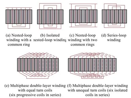
Fig.7 Available rotor winding structures for BDFIM
3.2.2 BDFRM
The idea that short-circuited coils of the BDFIM can be replaced by high-reluctance flux barriers to cause similar opposition to the magnetic flux has come through in the BDFRM[9]. It has been shown that any available rotor type used for synchronous reluctance machines (SynRMs) is essentially applicable in the BDFRM, i.e., the simple salient-pole rotor[27],axially-laminated anisotropic rotor[28]and multi-layer flux-barrier rotor[29]shown in Fig.8. The simple salient-pole rotor employs alternative variation of magnetic reluctance of salient-pole blocks to modify the harmonic spectrum of MMF distribution, while the axially-laminated anisotropic rotor and multi-layer flux-barrier rotor make full use of the non-uniform distribution of MMF along the airgap circumference to produce new spatial harmonic spectrums[5]. Whilst all of them can serve the purpose as the intermediate between the PW and CW, the performance like cross-coupling capability, torque density, core losses, etc., varies significantly with the rotor type, as discussed in [30-32].An axial-flux dual-stator counterpart has been recently proposed to improve the torque density and enable the more flexible rotor pole shape design[33].
3.2.3 BDFM with a hybrid rotor
To further improve the cross-coupling capability, a hybrid rotor shown in Fig.9(a) which integrates short-circuited coils and multi-layer flux-barriers has been proposed, analyzed and used in a BDFM[34]and brushless EESM[10], the latter being a special case of the BDFM with dc supplied CW. A similar hybrid structure in Fig.9(b) has also been derived from the BDFIM with a nested-loop rotor by introducing axial ducts with an incentive to reduce the overall weight of the rotor. The ducts also serve as the flux barriers in isolating the magnetic circuits occupied by adjacent copper nests[11].As a result, the rotor shown in Fig.9(b) can be treated as a combination of the nested-loop rotor and a flux-barrier rotor.
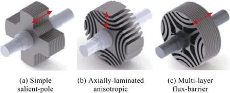
Fig.8 The BDFRM rotor designs (arrow: lamination direction)
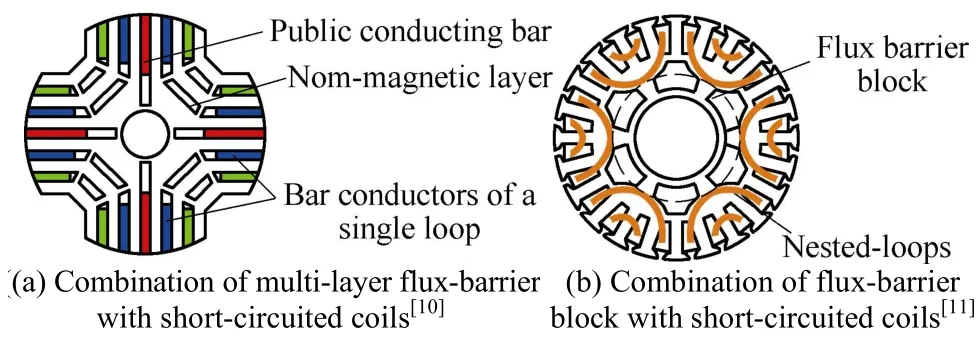
Fig.9 Hybrid rotor configurations for the BDFM
4 Modeling techniques
Modeling approaches widely used for conventional ac machines, including the electromagnetic-field-based and electric-circuit-based, can be equally applied to the BDFMs. A detailed classification is shown in Fig.10.
4.1 Electromagnetic-field-based modeling
The one-dimensional harmonic analysis, assuming a linear magnetic circuit, is primarily used to explain the operating principles of the modulation type and to predict the frequency-domain characteristics for torque ripples, currents and voltages[20,35,36]. To accurately calculate the steady-state and dynamic performance of the BDFMs, especially with additional rotor circuit, iron losses and saturation effects considered, time-consuming time-stepping finite element analyses (FEAs) are usually conducted[37-39]. Various magnetic equivalent circuit(MEC) models[40-42]and a magnetostatic finite element(FE) method based on space-time transformations[43]were later developed to reduce the calculation time,while still maintaining acceptable results for the population-based optimization.
4.2 Electric-circuit-based modeling
The steady-state operation of the BDFM is normally studied using a per-phase EEC. The operating limits,maximum torque capability and volt-ampere requirements for control of the CDFIM were investigated by applying the standard EEC shown in Fig.11(a), albeit with parameters referred to the rotor side[44]. Two additional constant shunt core loss resistances were employed to improve the EEC quality in [16], with emphasis being made on frequency constraints for synchronous operation, active-reactive power flow, and converter rating. In order to account for the influence of core losses more accurately and to make the entire model realistic, variable iron loss resistances were added to both stator and rotor sides[45].

Fig.10 The classification of the BDFMs modeling methods
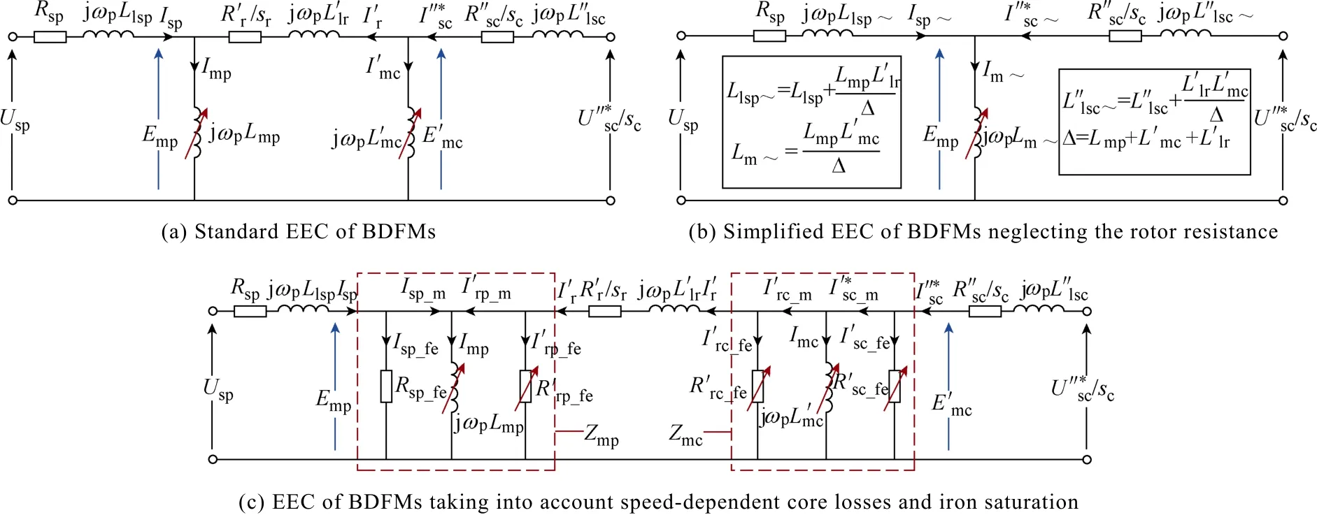
Fig.11 EECs of BDFMs with rotor windings and parameters referred to the PW side(note: resistances/inductances crossed by red arrows are variable)
The standard EEC was also conceptually developed for the steady-state analysis of the BDFIMs by analogy to the conventional one for IMs[46]as depicted in Fig.11(a).The logic behind this was based on the perception that the BDFIMs can be functionally treated as two cascaded IMs built in the same frame. Considering that the BDFIM usually has a small rotor resistance and operates at relatively large slip frequency, the EEC can be simplified to that in Fig.11(b)[47]. The standard EEC can be further improved by integrating speed-dependent resistances in parallel with the PW and CW magnetizing branches to properly take core losses into consideration[48]as illustrated in Fig.11(c). Voltage equations in phasor notation and the corresponding steady-state EEC have also been derived to study the asynchronous and doubly-fed synchronous operation of BDFRM[9].
In the electric-circuit-based modeling, accurate parameter identification is challenging, especially for topologies with short-circuited rotor windings which is impossible to have a direct physical access without extra hardware. All the EEC parameters in the standard EEC depicted in Fig.11(a) (i.e., 3 resistances, 3 leakage inductances and 2 magnetizing inductances) can be readily calculated using the established empirical formulas and facilitated magnetic circuit methods for conventional machines[49-50], but the accuracy cannot be guaranteed since the BDFMs are usually designed with some degree of saturation to fully utilize the core material. Therefore, experimental extraction of parameters is more attractive. Standard no-load and locked-rotor tests for IMs were used in [51] with 1%~7% of the stator winding inductance being assigned to the leakage component for ease of parameter separation. An off-line estimation method in frequency domain was first implemented to find the resistances and inductances of the BDFIM for a range of excitation frequencies[52]. An alternative way is transforming the standard EEC to reduce the number of unknown parameters first and then curve-fitting the torque-speed characteristics obtained from both simple and cascade induction modes to complete the parameter estimation[46].An off-line identification method using pseudo-random binary signal excitation and recursive least squares estimation was successfully applied to the BDFIM recently to determine the full EEC parameter set[53].Given that the three resistances are measurable, the five inductances can be solved out by the semi-definite programming based on no-load and stand-alone load tests[54].
Even for the BDFRM which has no rotor windings,the high leakage inductances also adversely impact the accuracy of conventional off-line parameter testing, and open-circuit or pulse tests are recommended instead[55].The practical BDFM dynamic models primarily include the full-coupled circuit model and the two-axis (d-q) or space-vector models in various reference frames. In the CDFIM case, the latter can be in power/control stator frame, rotating frames locked with the rotor or PW/CW flux (field), or even in an arbitrary reference frame as developed in [56]. The two- axis model for the BDFIM in a rotor frame was for the first time established for computer simulations[57], based upon which a rotor-FOC(RFOC) scheme with an unusual decoupling technique was proposed in [58]. However, the aforementioned models for the BDFIM with a nested-loop rotor have neglected the individual effects of multiple loops per nest by conceptually and unwarrantedly replacing them with an equivalent single loop. Such an approximation is essentially a model order reduction problem and it appears to be justified with a minimum loss of accuracy as initially observed in [59] and later solved in [60]. The reduced-order d-q model of the BDFIM in a unified reference frame was developed for the stator-fluxoriented controller design[61-62]. The most compact version of a space vector model with multi-loop circuit equations was subsequently built for BDFIM performance predictions and control without compromising much on accuracy[63]. Similarly, the fundamental theory and dynamic models of the BDFRM have also been developed and thoroughly investigated[64-66].
In addition to the ordinary modeling routines,several new methods have also been proposed, such as the dynamic EEC for CDFIM control by applying the inverse model principle[67], and the spiral vector modeling of the DS-BDFIM for unified steady-state and dynamic analysis[68].
5 Modes of operation
The presence of two physical electrical ports benefits the BDFMs with a variety of available operating modes,which have been clearly defined and experimentally identified in [38, 68] and [69]. Note that in this section,the BDFM in all available modes of operation are not necessarily grid-connected. They can be supplied by converters too.
5.1 Simple induction mode
The BDFM works in this mode if one of the two electrical ports is open-circuited while the other is supplied. It only appears in BDFM topologies with rotor windings and is essentially an IM with a substantially increased secondary leakage inductance contributed by the magnetizing inductance of the open-circuited side.The torque capability is thus significantly reduced even when the rated voltage is applied, as depicted by the dash line in Fig.12(a). This mode of operation can be effectively used to measure the cross-coupling characteristics[45].
5.2 Cascade induction mode
If one of the two electrical ports is short-circuited and the other supplied, the BDFM will operate in the cascade induction mode. Taking the sum cascading (or sum modulation) case as an example, in the vicinity of the natural synchronous speed, the retarding torque coming from the interaction between the shorted stator windings and the rotor successfully prevents the rotor from exceeding the natural speed in motoring operation,so the BDFM can be fully controlled by external resistances connected to the CW or constant V/f supply connected to the PW as a motor. As indicated by the torque-speed characteristic (solid line in Fig.12(a)), the torque-curve in the full speed range is essentially the sum of two IMs, one with the pole pair number of the PW and the other the equivalent pole pair number (pp+pc).The torque production in this mode is comparable to that of a single IM within the cascade construction, so it can be used in practical motoring or generating regimes. A special application of the cascade induction mode is to start up the machine from standstill[70-72].
5.3 Singly-fed synchronous mode
If the two electrical ports are dc and ac fed, the BDFM rotor would be naturally locked into synchronism emulating a brushless EESM with (pp+pc) pole-pairs[10].This mode of operation is also versatile and applicable to any BDFM.
5.4 Doubly-fed asynchronous mode
When both electrical ports are ac supplied, but the synchronous operation is not achieved, the BDFM works in the doubly-fed asynchronous mode, which has also been referred to as double-cascade mode[69]. It occurs in cases where the converter or controller fails to meet the frequency constraint stipulated by (1). The resultant torque characteristic can be predicted as a simple superposition of two cascade induction modes, one supplied at the PW terminal and the other from the CW side, as shown in Fig.12(b). The operating point is determined by the individual torque profiles of both IMs and the load condition.
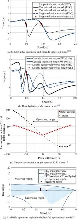
Fig.12 Torque-speed characteristics of the DS-BDFIM(normalized relative to the PW synchronous speed)
5.5 Doubly-fed synchronous mode
If both electrical ports are supplied from ac sources,and the frequency relationship given by (1) is preserved by the controller, the BDFM is in the doubly-fed synchronous mode. In this regime, the BDFM performance resembles that of a classical SM and the corresponding torque-angle characteristic is a pure sine-wave offset by dc asynchronous torque components,as shown in Fig.12(c)[17]. The available operation region is outlined in Fig.12(d). It can be seen that the speed-dependent torque capability decreases near the natural and PW synchronous speeds.
There are two complex control variables, i.e., the current and voltage vectors of the PW and/or CW. In principle, either a single-electrical-port control scheme(only one of the electrical ports is actively controlled)[73]or a dual-electrical-port counterpart (both electrical ports are simultaneously regulated)[74-76]can be adopted. In the former option, the PW is usually grid-connected at a constant voltage and frequency, and the CW is supplied from a variable voltage and frequency converter. In the latter case, both the PW and CW are converter-fed. The comparative properties of the two control approaches appear in Table 1.
6 Design considerations
Though the BDFM origins date back to early 1900s,little progress has been made in design methodology until the recent decade, which can be mainly attributed to the obvious distinctions in power flow and operating range between the BDFMs and conventional singly-fed machines. The well-established text-books design methods based on a single airgap volt-ampere rating for traditional dc machines, IMs and SMs are no longer applicable. Therefore, nearly all the early proof-ofconcept prototypes, as summarized in [2] and [4], were obtained by rewinding the stator and replacing the rotor of standard IMs. Existing research on the design of BDFMs mainly focus on the modulation type considering their harmonic related issues including torque ripples, time-harmonic distortions, iron saturation,core losses, vibration and acoustic noise, as discussed below.
6.1 Torque ripple and time-harmonic distortion
There will exist a plural of low-order space harmonics mainly due to the asynchronous modulating action of the special rotors in the modulation type if the machine is not well designed. The crowded field harmonics further induce time harmonics in the stator and rotor windings producing undesired distortions of the respective current and voltage waveforms. The frequencies of torque ripples, voltages and currents,which are rotor-speed-dependent, can be well predicted by harmonic analysis[20,35-36]based on which the commonly-used rotor/stator skewing or tooth notching can be introduced into the BDFIM to substantially reduce the torque ripple and total harmonic distortion(THD) of rotor currents[77].
6.2 Iron saturation
Since the BDFMs are usually used as an adjustable speed constant frequency generator or motor with the converter-fed CW, the variable flux level of the CW is very likely to bring the laminated core into saturation for all BDFMs, especially at the upper band of the speed range[42]. Aside from this operating feature, the modulation type may also suffer from more severe saturation due to the superposition of multiple asynchronous field harmonics. It should be noted that,this saturation phenomenon is usually localized instead of spreading out to the whole magnetic circuit, as pointed out in [78]. The performance considering iron saturation is usually investigated by introducing variable main inductances in the full coupled-circuit model[79]or the steady-state EEC model[44-45]. The saturation effects induce distortions not only of the airgap field distribution but also the torque-angle characteristic.Therefore, they should be taken into account from the original initial sizing to the design optimization stages.
6.3 Core losses
The multi-harmonic feature of the modulation type makes the calculation of core losses much more complex than with the conventional machines. A modified Steinmetz equation is applied for this purpose in the BDFIM to address the issues caused by magnetic fields of different frequencies[41-42,80]. Experimental measurements show that calculations of core loss using the modified Steinmetz equation and core loss curves provided by steel manufacturer generally yield acceptable results,which otherwise will be significantly underestimated by empirical core loss equations for conventional machine design[41,80]. A detailed comparison between a BDFIM and a DFIM of the same power rating and operating range indicates that the core loss of the BDFIM is roughly doubled compared with the DFIM[81]. The obtained core loss results can then be used in EEC models to further predict the steady-state characteristics of the BDFMs by incorporating speed-dependent core loss resistances, as elaborated in Section 4.2.
6.4 Vibration and acoustic noise
The vibration mode of the CDFIM is the same as the DFIM’s, but for the modulation type, additional pole-pair-combination-dependent vibration modesalways exist[81]even the unbalanced magnetic pull and rotor eccentricity—the main contributors of vibration and noise in conventional machines—are successfully avoided. A larger difference between the PW and CW pole pairs, i.e., far-ratio pole-pair combination, is preferred to avoid low-order vibration levels[82].

Table 1 Comparison of single-electrical-port and dual-electrical-port control schemes of the BDFM
7 Control strategies
As mentioned in Section 5.5, the BDFMs can be configured in a single-electrical-port or dual-electricalport scheme depending on the specific application,yielding two distinct control scenarios. The majority of the existing literature deals with the single-electricalport control schemes, where the CW voltages and/or currents are directly manipulated to regulate the active and reactive power (grid-connected generation), voltage/frequency (stand-alone generation) or electro-magnetic torque (grid-connected motoring), so advances in single-electrical-port control are primarily surveyed in this section.
7.1 Sensored control of grid-connected BDFMs
7.1.1 Scalar control
According to (1), the rotor speed can be controlled in an open-loop fashion by simply setting the PW and CW frequencies for the doubly-fed synchronous operation. A standard procedure from the asynchronous start-up to the pull-in synchronization similar to that used for the classical wound-rotor SM is usually required.
By analogy to the slip-ring DFIM operated in doubly-fed synchronous mode, all BDFMs face the open-loop instability problems over most of the potentially useful operating region due to the inherent lack of damping[83]. The open-loop stability analysis has revealed that the stable margin is closely related to both the EEC and mechanical (e.g., inertia and friction coefficient) parameters[84-85]as well as the loading conditions[86]. In order to stabilize BDFMs over the required speed range, closed-loop controllers have to be incorporated.
Owing to its simplicity and relatively low cost of implementation, closed-loop scalar control is the first to be considered. It has been found that, the constant V/f or current control, although by no means optimal, can provide sound performance in a narrow range around the natural synchronous speed for the CDFIM[87], the BDFIM[88], and the BDFRM[89]. The torque can be controlled by adjusting either the CW current[90]or the phase of CW voltage[71]whilst the frequency and V/f ratio are specified in an open-loop manner by synchronous operation constraint.
7.1.2 Field-oriented control
The stator-FOC (SFOC) of the CDFIM in stator-flux reference frame was implemented in [91],and later in [92,93], achieving approximately decoupled active-reactive power control (the active power or speed/torque can be manipulated by the CW q-axis current and the reactive power by the d-axis component)in the desired range around the natural synchronous speed. Cross-coupling between the d-q axes in the outer power/speed loop introduced by the rotor resistive effects was for the first time addressed and compensated for in each axis by PI regulators in [91]. However, little attention had been paid to the cross-coupling between the d-q axes in the inner current loop (introduced by the PW and RW) until [94], where the inner current loop was fully modeled and then simplified to derive a simple but effective feedforward item to improve the stability and dynamic response.
Combined-magnetizing-flux-oriented torque control was implemented in [95], but at the expense of coupled active and reactive power variations. The RFOC was also proposed for the BDFIM in [58] and later used for torque control of the CDFIM with the rated torque sharing ratio to avoid over-rating of one of the two DFIMs[96]. The underlying model was formulated in double (PW and CW)-synchronous reference frames and it was heavily machine-parameter-reliant which significantly reduced the RFOC robustness. It has been revealed that the RFOC and SFOC can provide a fairly consistent response though the former prefers to use amplitude and phase angle as control variables whereas d-q variables are more suitable for the SFOC[73]. Usually two PI stages (e.g. one for the outer power/speed loop and the other for the inner current loop) are required if the CW voltage vector is chosen as a control variable.An enhanced version with an additional PW current PI loop and a simplified one (i.e., single PI) omitting the inner current loop are respectively presented in [61]and[62].
Benefiting from the cage-less rotor and hence fewer machine parameter dependence, the PW real power (or torque in motoring regime) and reactive power control of the BDFRM is inherently decoupled and much simpler relative to its BDFIM companion. The SFOC of the BDFRM, which has similar model equations and control structure as the DFIM despite the fundamentally distinct operating principles, was originally proposed in[97]. The dynamic responses under fixed and/or variable loading conditions were not thoroughly investigated until very recently in [98] and [99], where the influence of PW resistance (i.e., differences between the field and voltage vector orientated control) with reduced machine sizes was for the first time discussed and supported by compelling experimental results.
To date, the only stability study of the closed-loop operation of the BDFM was conducted on the DFIM,considering its similarities with the BDFRM in dynamic model. The study shows that the FOC instability comes from the out-of-sync between the reference frame and stator flux positions. To stabilize the system, either the field orientation process should be fast enough in computation, or a supplementary controller must be designed to compensate for the lack of sufficient system damping for flux fluctuations[86].
7.1.3 Direct control methods
The dynamic vector model also facilitates the development of direct torque control[100]or direct power control (DPC)[101]with sound performance obtained for the CDFIM using simple switching tables and neglecting the rotor resistance. Under this circumstance, the CDFIM can be treated as a DFIM with modified mutual and leakage inductances. Thus the direct torque control(DTC), and the associated grid synchronization method of DFIM based on the concept of virtual torque (or virtual complex power for DPC), can be readily applied to the CDFIM. A smooth and fast synchronization can be achieved without inrush currents, no PLL, PI regulators or rotor position/speed information normally required by the FOC[102], as demonstrated in [100] and[103].
A so-called predictive DTC for the BDFIM,employing PI controllers and a pulse-width-modulated(PWM) inverter was proposed in [104] as an alternative to the commonly-used DTC with hysteresis comparators.The classical switching-table-based hysteresis DTC was implemented on the BDFIM in [105], but with degraded performance experienced even at a fast sampling rate(100μs), mainly due to the non-optimal prototype design abundant in spatial harmonics[51].
By the absence of the rotor windings, the DTC for the BDFRM can largely inherit from that of the slip-ring DFIM, as demonstrated in [106] (i.e. the switchingtable-based) and [107] (i.e. with space vector PWM). An improved DTC technique with indirect stator-quantities control (ISC) for the BDFIM was proposed to eliminate the complex rotating coordinate transformations (i.e. the CW flux components should be estimated in, or converted to, a stationary frame for the sector detection)and reduce the parameter dependence(as both the CW flux and torque estimation involve inductances)[108-109].
Apart from the considered field-oriented control and direct control methods, a robust control algorithm based on the integral sliding mode control (SMC) for the BDFIM was proposed to eliminate the speed error and compensate the system uncertainties caused by the rotor flux and parameter variations, while achieving the approximately decoupled control of rotor speed and reactive power[110]. Another super-twisting sliding mode direct power control was proposed to lower the power ripple and THDs of the PW and CW currents[111]. Model predictive control (MPC) has also been proposed for the BDFMs recently[112]. The feedback linearization (FBL)has been applied to the BDFIM, yet suffering from sensitivity issues[2].
7.1.4 Control strategies under unbalanced or grid fault conditions
In grid-connected applications, the BDFM is required to have the ability to mitigate the adverse effects of unbalanced or even distorted network conditions. A control scheme based on power compensation under unbalanced grid conditions was proposed for DPC of the CDFIM to eliminate the negative-sequence components of the PW currents and to improve the power quality[101]. A dual PI vector control algorithm in two synchronous reference frames for the BDFIM was put forward to regulate the positive-sequence components for control of active and reactive power, and the negative counterparts for other control targets[113]. The further dynamic performance boost was accomplished using a proportional integral resonant (PI+R) controller in a single synchronous reference frame[114].
With respect to the LVRT, it has been reported that the CDFIM and BDFIM exhibit milder transients relative to the DFIM regarding the currents, DC-link voltage, electro-magnetic torque and turbine speed under serious voltage dips[115], showing greater potential for grid code compliance. Crowbar-less LVRT of the BDFIM has been demonstrated to be feasible for both symmetrical and asymmetrical faults[116-117], owing to the inherently larger rotor leakage inductance effectively limiting the CW current levels during voltage transients.However, the increased rotor leakage inductance makes it difficult for the machine side converter (MSC) to control the PW reactive power[118], indicating that further measures are still necessary in this direction to allow the BDFIM to fully satisfy the grid integration requirements[119]. A crowbar or a series dynamic resistor commonly used in conventional DFIM systems[120]and an improved LVRT control strategy based on the flux linkage tracking[121]are suggested for this purpose.
7.2 Sensored control of stand-alone BDFM system
Vector control with CW current orientation is widely used to stabilize the output voltage amplitude and frequency of BDFM-based stand-alone power generation systems regardless of the varying rotor speed and loading conditions[122-130]. The CW-current-oriented control with simplified dual-closed-loop scheme(i.e.,outer voltage/frequency loop and inner current loop) was first presented in [122]. However, unexpected fluctuations in the output voltage amplitude were observed with IM loads and a compensation strategy based on synchronous sampling and harmonic injection was proposed in [123].Other control options, i.e., with CW voltage and/or flux alignment were modeled and compared with CW current oriented control in [124].
The cross-coupling effects between the d-q axes in the inner current loop(introduced by the PW and RW)observed within grid-connected BDFM systems also appear in stand-alone applications, slowing down the transient response of the output voltage. Commonlyused feedforward approaches[125]and a new decoupling network method[126]have been implemented for this reason. A frequency-domain method based on numerical calculation of transfer functions was proposed to better design the voltage and current PI regulators, which has provided fast dynamic performance without the need for feedforward terms[127]. Unbalanced and low-order harmonic voltages arising from non-linear loads can be suppressed by injecting harmonic current components into the CW[128].
The line side converter(LSC) can also be fully used to alleviate the load disturbance implications, although only balanced and linear loads have currently been considered, and thus enhance the voltage quality of the point-of-common coupling(PCC) (i.e., where the LSC and PW are connected) through control of LSC reactive current[129]. DC-link current feedforward is suggested to stabilize the DC-link voltage and speed up the LSC dynamic response[130].
7.3 Sensorless control
At present, the sensorless control of the BDFMs is lagging far behind its DFIM counterpart, primarily due to the model complexity and/or the strong parameter dependence. To date, the BDFRM has achieved more than satisfactory sensorless operation[106,131-136]. A lowcost position sensorless control scheme for the BDFRM was first realized by affecting the torque angle in a closed-loop manner, while the speed command is implicated in the rotational angle used for coordinate transformations[131]. An encoder-less DTC scheme was proposed for speed regulation in [106], but the flux estimation suffered from high sensitivity to inductance knowledge uncertainties in real-time implementation. By replacing the CW flux with reactive power as the control variable, the nearly parameter-independent (only the PW resistance used) torque and reactive power control is realized. However, for speed control, either a shaft encoder or a rotor speed observer is still required[132].Instead of using the torque and flux as control variables,which are more susceptible to estimation errors, the measurable active and reactive power are directly controlled in[133]. The performance is improved in comparison to methods used in [106] and[132] owing to the use of active voltage vectors only and a CW-flux-independent sector identification technique.Recently, a sensorless FOC scheme for speed regulation has been developed to address the variable switching frequency and flux (torque) ripple issues of the original encoder-less DTC[134]. Model reference adaptive systems(MRASs) with CW flux and reactive power control were implemented in [135] and [136] respectively to estimate the rotor speed, indicating good speed tracking abilities of the controller.
Sensorless control of the BDFIM was first implemented using a modified EEC model derived from the standard configuration shown in Fig.11(a) to separate the magnetizing and torque-producing current components by referring the PW and RW leakage inductance terms to the CW side[137]. However, the usual CW terminal voltage integration used to estimate the respective flux vector is highly inaccurate near the natural synchronous speed. It is caused by the well-known adverse effects of resistance variations at low supply voltages. A MRAS observer based on the CW current and a rotor speed estimator was proposed to achieve sensorless control of rotor speed[138].
Sensorless stand-alone generating operation of the BDFM has also drawn increasing attention recently.Based on the voltage control scheme discussed in Section 7.2, the PW q-axis voltage was regulated to estimate the CW frequency, and the rotor speed can then be immediately obtained from (1)[139]. The new speed observer based on a rotor position PLL and a second-order generalized integrator was implemented for different loads in [140].
7.4 Control comparisons of BDFM and DFIM
Given the inductances are constant, there will be two more cross-couplings between the d-q axes in the BDFIM and CDFIM imposed by the rotor resistance,one for each control loop(outer and inner for currents). It has been found that, in the case of outer power/speed control loop, this can be quantitatively measured by a dimensionless number σ—the product of the slip frequency and transient time constant of the rotor, which can be expressed as follows:

The larger σ is, the weaker the cross-coupling between the axes will be, and the better decoupled control can be achieved[73,92]. If σ is big enough, then ignoring the rotor resistance will result in a DFIM-like control property of the BDFM. Parameters and calculated σ values at 0.7 and 1.3 times the natural synchronous speed(σ0.7and σ1.3respectively) are tabulated in Table 2. It can be seen that, the rotor transient time constant is heavily reliant on the machine design. However, the pole pair combination plays a more significant role in the σ magnitude. Generally, pp<pc(for the BDFIM) and pp=pc(for the CDFIM) yield larger σ values. A larger σ indicates a better control property similar to the DFIM’s within the desired speed range(±30% natural synchronous speed), but a slight increase in rotor core losses can be expected. The cross-coupling between dq axes in inner current loop is usually compensated by a series of feedforward terms.
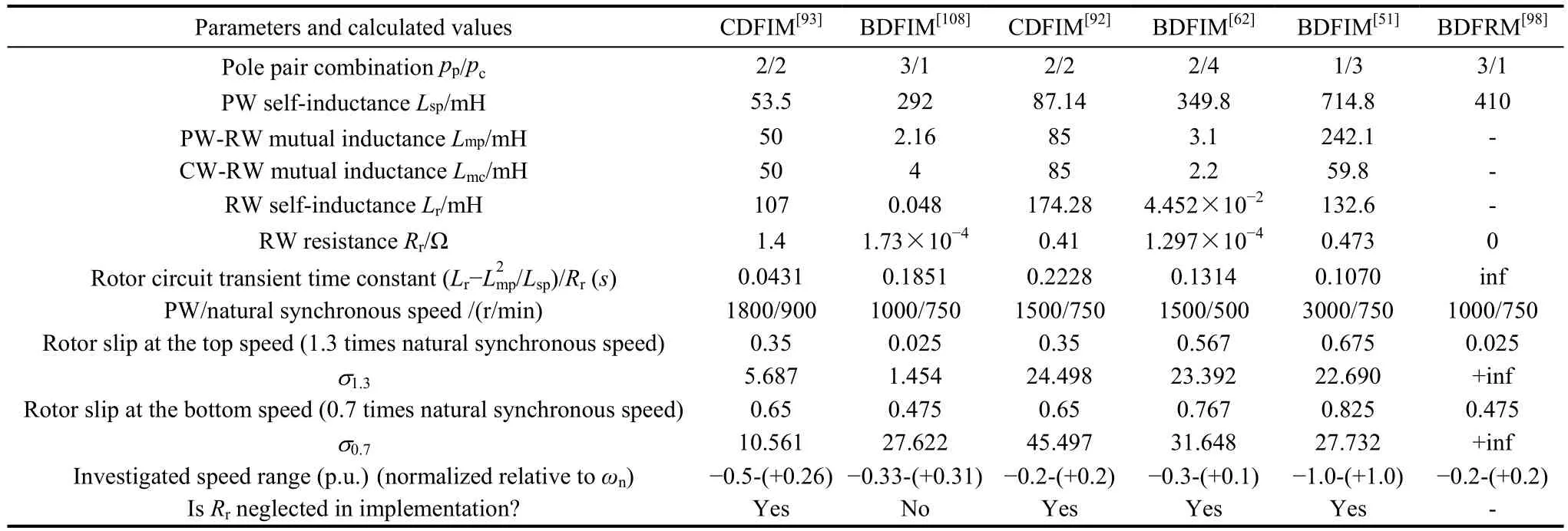
Table 2 Comparison of cross-coupling of different BDFMs between dq axes in outer control loop
An inductor-capacitor(LC) filter is usually installed between the MSC and the CW to eradicate the high-frequency PWM voltage harmonics since BDFMs are more sensitive to harmonic contamination[125]compared with the DFIM. Current hysteresis PWM and classical DTC prohibit the use of filter and the quality of output voltage at PW terminal will be seriously deteriorated in stand-alone systems.
8 Concluding remarks and future trends
Based on the systematic review of the existing BDFMs in terms of topology, operating principles,modeling, control and applications, it is found that though highly-reliable and cost-effective, BDFMs generally feature relatively lower torque/power density,inferior efficiency and harmonic-related issues (for the modulation type) compared with the conventional DFIM.This is largely due to the fact that they employ indirect magnetic coupling instead of directly using fundamental flux/field components to realize the slip power transfer.The torque/power density may be elevated to the level on a par with standard industrial IMs by further design optimization as demonstrated in [39] and [42]. The efficiency can also be improved by more optimal design or introducing reactive compensation devices at PCC[42,141]. The most challenging part may lie in the mitigation of harmonic-related issues (e.g., additional losses, lower output power quality, vibration and acoustic noise) inherited from the multi-harmonic nature of the modulation type especially under heavy or even overload conditions, though they can be alleviated to some extent by sophisticated design and control techniques, such as the work done in [82, 113, 114] and[123]. As a consequence, the development of a successful BDFM-based system is faced with a number of tradeoffs between:
· The torque/power density and the efficiency[39,42].
· The power factor (or reactive power capability) of the PW and the volt-ampere rating of the MSC supplying the CW[141-143].
· The torque density and vibration behavior in the selection of suitable pole-pair combination[81,144].
· The control property and rotor core losses (or efficiency) in determining the rated operating point[45].
· The PW reactive power capability and the LVRT performance in design of rotor leakage inductance for grid-connected wind power applications[118-119].
· The electromagnetic performance and manufacturing cost[26,145].
The above compromises pose tough challenges on the design of the BDFM-based systems, which means the points of concern in design stage should be addressed according to specific applications since not all the desired performance indexes can be simultaneously achieved. In addition, the rotor structure, including the pole pair combination[78,144]and detailed geometrical variations[146]which primarily affect the similarity between the practical rotor construction and the idealized airgap field modulator, have been demonstrated to have significant influence on the performance of BDFMs.Therefore the rotor design and manufacture is crucial and optimization on a multi-objective basis is necessary.
With respect to the modeling methods, the harmonic analysis proves to be rather effective for explaining the operating principle of the BDFIM.Steady-state analysis relies on the per-phase EEC, while the dynamic performance is usually studied by two-axis or space vector models. These methods are quite time-saving with acceptable accuracy. However, for higher accuracy, FE methods are more appealing.Special features of BDFM rotors, such as the self-closed rotor circuit (CDFIM and BDFIM), axial lamination or thin rib (BDFRM), etc., unavoidably complicate the FEA and under most circumstances, fine meshing and time-consuming time-stepping FE analysis are required.MEC[40-42], computationally efficient FE methods[43]and semi-analytical methods[147], for population-based design optimizations are meaningful explorations in this direction.
Thanks to the past decade's exhaustive research, all available functional modes of BDFMs have been identified. However, little attention has been paid to the utilization of other operating modes except for the doubly-fed synchronous operation and transitions between them, which shows promise in fail-safe post-fault conditions.
Substantial knowledge has been gained on control aspects. A detailed qualitative comparison of various control methods reviewed in Section 7 is listed in Table 3.It can be seen that FOC for sensored grid-connected applications and voltage control for stand-alone BDFM systems (sensored or sensorless) have the highest technical maturity, and are the mainstream for the time being. In both control strategies, the cross-coupling phenomena between dq axes in the power/speed and/or current loops coming from resistive effects have been extensively investigated, and several new methods proposed and implemented to achieve satisfactory decoupled control. In contrast to FOC, the DT(P)C is a rather competitive alternative for sensorless control of the BDFMs. Developing robust control schemes for BDFMs with superior immunity to parameter variations and disturbances is the next step, as pioneered by the recent research work in [108, 126, 133].
Advantages and limitations of the prevailing BDFM topologies have been identified and compared with the established DFIM as tabulated in Table 4. It can be seen that peculiarities of the BDFM result in distinct differences from the more traditional singly-fed machines and slip-ring DFIM in design, analysis, control and even manufacturing. Advances in the field of the BDFM have already been an indispensable complement and invaluable contribution to the existing theories of electric machinery. For instance, the general airgap field modulation theory proposed in [5] was based on the development of BDFMs.
In contrast, the practical application of BDFMs has been greatly challenged mainly due to its relatively low torque/power density and efficiency compared with the conventional singly-fed machines and slip-ring doublyfed machines. To date, several large BDFMs have been prototyped as the milestones on the way to practicaldeployment of BDFMs for wind energy conversion systems (e.g., the 90kW DFIM-RT[7], the 200kW BDFRM[145]and the 250kW BDFIM[116]) or ship shaft power generation (e.g., the 64kW wound rotor BDFIM[129]). With the irreplaceable virtues of unique variable speed constant frequency characteristics, robust construction, fail-safe operating nature, and flexible power flow, in addition to the technically demonstrated pump drives and wind turbines, the BDFMs may also play an important role in some safety-critical applications where the performance of the conventional singly-fed machines will unavoidably be compromised by the fault-tolerant design techniques, such as motors/generators for variable-frequency ac aerospace networks.

Table 3 Comparison of control methods of the BDFM
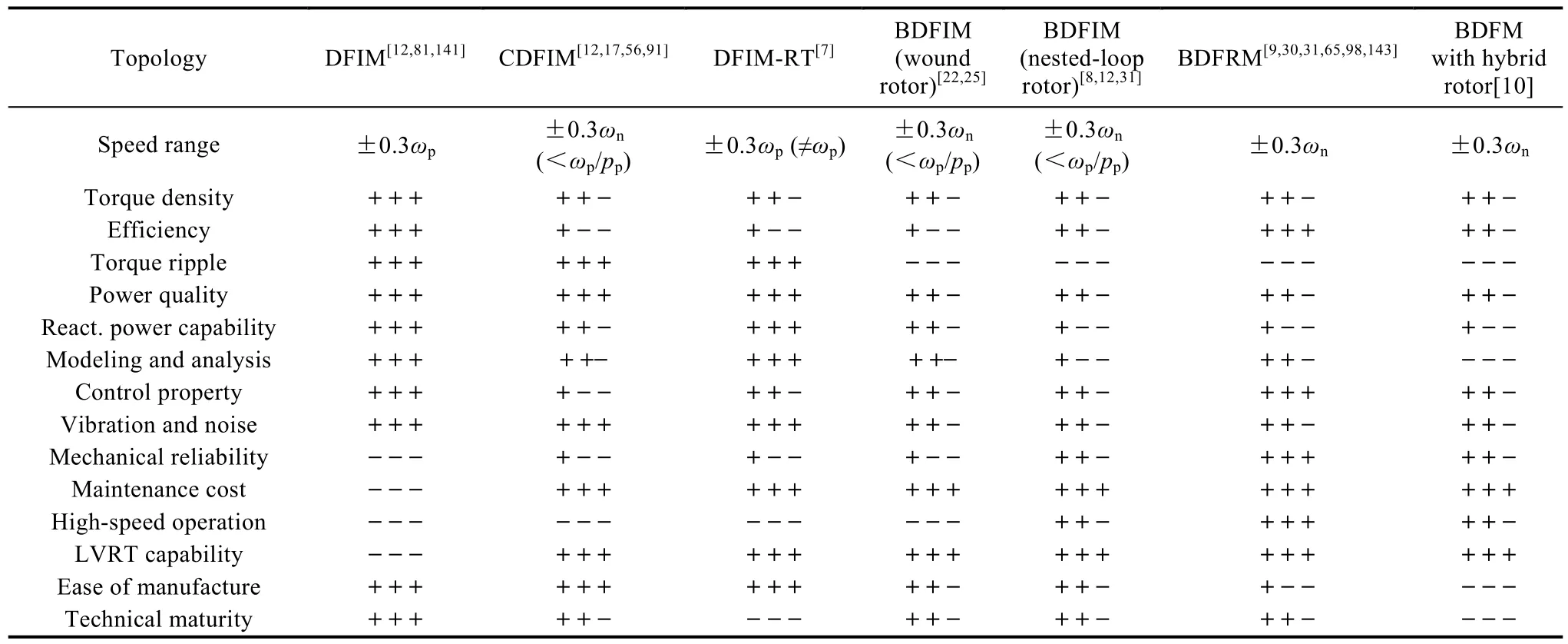
Table 4 Comparison of conventional DFIM and various emerging BDFM technologies for ±30% limited speed range applications
 Chinese Journal of Electrical Engineering2018年2期
- Chinese Journal of Electrical Engineering的其它文章
- Control and Applications of Direct Matrix Converters: A Review
- An Optimal Charging/Discharging Strategy for Smart Electrical Car Parks
- Two-Stage Transformerless Dual-Buck PV Grid-Connected Inverters with High Efficiency
- A New Active Gate Driver for MOSFET to Suppress Turn-Off Spike and Oscillation
- Dual-Coupled Robust Wireless Power Transfer Based on Parity-Time-symmetric Model
- A Modular DC/DC Photovoltic Generation System for HVDC Grid Connection
