A Critical Topology Review of Power Electronic Transformers: In View of Efficiency
Guidong Zhang, Jie Chen, Bo Zhang, and Yun Zhang*
(1. School of Automation, Guangdong University of Technology, Guangzhou 510006, China;2. South China University of Technology, Guangzhou 510006, China)
Abstract: Design of power electronic transformers is a hot research topic and its efficiency improvement is a critical problem all over the world. It is also the largest barrier hindering the application of power electronic transformers in industry. In this paper, the state of power electronic transformers is fully presented in terms of efficiency improvements. It is followed by the efficiency modeling of several typical topologies, and their detailed analysis and comparisons. Then, the corresponding industrial application scope of these topologies is presented, providing theoretical guidance for their industrial applications.
Keywords: Power electronic transformer, topology, efficiency, modeling.
1 Introduction
It is well known that smart grid and energy internet are the main power system focuses in the coming future.It is also known that renewable sources such as solar photovoltaic(PV) and wind energy will play a very important role in smart grid and energ y internet[1-2].Due to the intermittent features of renewable resources,there are many technical problems should be solved before entering smart grids, i.e., high efficiency and stabilization, which also raises many challenges for power electronics techniques[3-4]. For example, power transformers are one of the most important components.In smart grids, power transformers are required to deal with features of fault isolation, power quality control,harmonic suppression and other functions[5-7]. The traditional transformers in power grids are realized with magnetically coupled metals, so there are many obvious disadvantages, i.e. large volume, heavy weight, heavy pollution, high economic cost and high energy loss,which easily fulfill the requirements of smart grid and energy internet. It should be mentioned that the largest shortcoming is the fact that the traditional one's efficiency can only realize 60% at maximum. Therefore,it is necessary to further develop and investigate new power transformers to overcome the aforementioned shortcomings[8-10].
With the development of power electronic techniques and their controls, a totally-new transformer,power electronic transformers(PET), is proposed by the American Institute of Electric Power in 1995 for realizing voltage transformation and energy transfer in power system through power electronic transformation technology, and is getting more and more attention[11].PET not only has the functions of transformation,isolation and energy transmission of traditional power transformers, but also has the functions of power factor correction, power flow control, power quality improvement, system operation monitoring and AC/DC power interface. To date, PET has played an important and indispensable role in realizing smart grid and energy internet[12-14].
It is followed by a structure of power electronic transformer based on direct AC-AC conversion and high-frequency isolation, proposed in 1999[15].Compared with the traditional transformer, the improved PET has a smaller size, lighter weight, and higher efficiency. In 2000, ABB researchers proposed a three-phase AC-AC buck-boost converter[16]. The PET has a simple structure, easier control and fewer power devices, so its efficiency is improved. Restricted by power electronic power devices, the above AC-AC power electronic transformer topologies only apply to small power occasions. With the development of power electronic techniques and power electronic devices in recent years, domestic and foreign researchers have put forward a variety of PET topologies for high power occasions. In 2007, a 270kVA solid state transformer based on 10kV SiC power MOSFET has been proposed.Its capacity, frequency, AC input and DC output are 1.2MVA, 16.7Hz, 15kV, 800V, respectively, which have been implemented in railway traction field[17]. Owing to the ZVS turn-on of most switches, the losses in the SiC MOSFET and diodes are significantly reduced compared to hard-switched converters. In [18], a high-voltage high-frequency transformer design for a 7.2kV to 120V/240V 20kVA solid state transformer was proposed in 2010. The power electronic transformer has a high integration degree and few switching devices. Moreover,the low voltage side is reserved with a DC bus interface,which is then easy to power the DC load.
After decades of development, PET has encountered a bottleneck, i.e., efficiency problems. Therefore,improving the PET efficiency can greatly promote their applications and then can gradually replace bulky and high-cost power transformers. Therein, the topology of PET is the most critical factor in improving efficiency[19-20]. Switching loss takes up most of the entire loss of PET. Hence, it is the most straightforward way to improve PET efficiency, reducing both the number of switching tubes in the topology of PET and hence the switching loss.
This paper is organized as follows: In section 2, the efficiency model of PET is established and the efficient expression of PET is derived. The structure and efficiency of several typical PET topologies are analyzed in Section 3. In Section 4, an impedance network PET structure based on GaN and SiC devices is proposed.Finally, a conclusion is drawn in section 5.
2 The efficiency model of PET
This section will analyze the topology of PET based on optimum efficiency. Without considering the switching loss, assume that the input and the output parameters of PET are U1/U2=I2/I1=N, the number of switch tube on U1side and U2side are m and n,respectively. Hypothesizing that the on-state voltage drop of all switching tubes is vc. From U1to U2, it will through multi-layer voltage transformation, and its proportional relation is U1/vi=ai, where viis the i-th voltage transition from U1, aiis corresponding voltage ratio. There are a total of switches at this stage, where(i=0,1,2...). Finally, the switching loss expression in PET can be expressed as:

Therefore, the efficiency expression is:

From the Eq.(2), it can be concluded that the efficiency of PET is mainly determined by the following factors.
● The input voltage (U1). In the case where other parameters are unchanged, the higher the primary voltage of the PET is, the higher the efficiency is.When the input voltage increases, the voltage stress of the electronic device also needs to be improved.However, as current electronic device technology has difficulty dealing with high voltage stress, it is necessary to connect multiple switch tubes to achieve voltage-sharing.
● The number of intermediate transformations (i). When i=0, the voltage transformation is realized directly. As the number of i increases, its efficiency will decrease.This parameter is determined by the type of topology.
● The number of switch tubesis one of the main factors that affect the efficiency of PET.The number of switches in PET is determined by the topological structure. Therefore, it is an important method to improve PET efficiency by improving the PET topology, especially reducing the number of switch tubes.
● PET ratio (N). When the ratio is larger, the loss will be larger and the efficiency will be lower.
● Switch on-state voltage drop (vc). When the value is smaller, the efficiency of PET will be higher. This parameter is determined by the semiconductor parameters.
● The factors that affect PET efficiency also include whether soft switching are implemented in the converter[21-23].
In view of the above analysis, the following sections will focus on efficiency analysis on various topological structures and obtain the corresponding theoretical efficiency expressions.
3 Topology analysis of PET transformer based on optimal efficiency
This section will focus on efficiency, concluding and analyzing the structure of several typical topologies.
3.1 AC buck PET
In 1995, a research project sponsored by the American Institute of Electric Power developed solid-state transformer based on AC-AC conversion[11].As shown in Fig.1, the diodes and switch tubes of the traditional Buck circuit are replaced by a switch module and a switch module. There, each switch module has four switch tubes respectively. By changing the connection and control mode of the circuit, it can realize the functions of AC chopping control voltage regulation,single-phase bridge rectifier, Single-phase ac voltage regulator, and other functions. The circuit structure is simple and easy to implement, but has no electrical isolation cannot inhibit current harmonics and achieve power factor control (PFC).
According to the Eq.(2), the efficiency expression of the AC buck converter of PET is as follows:

From the Eq.(3), it can be concluded that the efficiency of this type is only related to the input voltage and the parameter of switches. Similarly, the same method can be applied to Boost, Buck-Boost, Cuk,Sepic converters, etc. The method is to replace the corresponding switches and diodes as bidirectional switch modules.
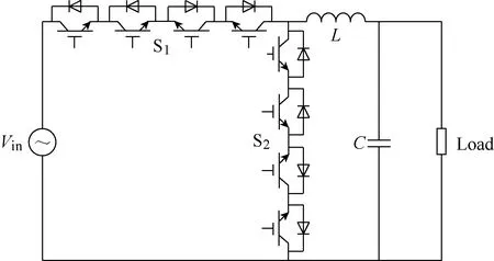
Fig.1 AC buck converter of PET
3.2 Flyback PET
The flyback topology of PET is shown in Fig.2. It is based on the isolation buck-boost converter topology,which only has two switch modules and can realize the function of increasing voltage and reducing voltage[16].However, the PET has a large harmonic voltage and intermittent current.
According to Eq.(2), the efficiency expression of the flyback topology of PET can be obtained as follows:
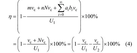
According to Eq.(4), the efficiency of this type of topology of PET is associated with the input and output voltage and the parameter of the switches. When the input and output voltage is high, its efficiency can be enhanced significantly. However, when the current is larger, the leakage inductance of the transformer will be larger. Therefore, the circuit is appropriate for highvoltage, small-current and low-power occasions.
Similarly, the analytical method and the efficiency estimation formula are also suitable for the Forward topology of PET.
3.3 AC-AC-AC PET
An AC-AC-AC transformer is shown in Fig.3. This topology was first proposed by Texas A&M University in 1999[15]. The topology is composed of high-frequency transformers and two H-bridge circuits of the primary and the secondary side. Each switch unit of H-bridge is composed of two IGBT modules to realize the bidirectional flow of energy. According to Eq.(2), the corresponding efficiency estimation formula can be obtained:

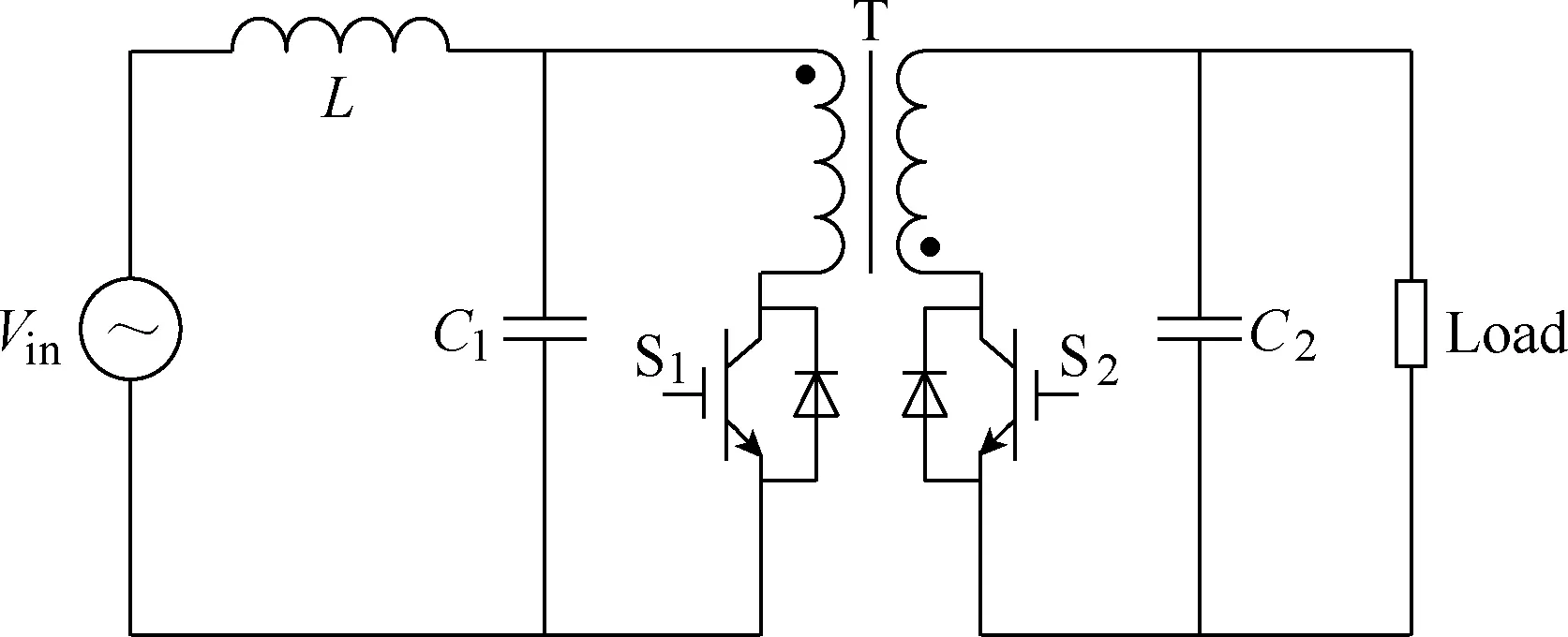
Fig.2 Flyback topology of PET

Fig.3 AC-AC-AC topology of PET
From Eq.(5), it can be concluded that the efficiency is related to the input voltage, the output voltage and the parameter of switches. The circuit of this topology of PET is complex and has high power loss because of the large number of devices (16 switches).
3.4 Matrix PET
As showed in Fig.4, the three-phase matrix topology of PET includes the modulation stage and the phase change phase[24]. The average voltage is modulated by the modulation phase, and then the voltage transformation is carried out. The topology can realize AC-AC transformation well and the voltage and current are continuous, while the circuit has more switches.
According to Eq.(2), we can get the efficiency of the expression as follow:

From Eq.(6), it can be concluded that the efficiency is related to the input voltage, the output voltage and the parameter of switch tube device. Compared with the AC-AC-AC topology of PET, the topology has complex control and stable output voltage.
3.5 AC-DC-AC PET
The typical AC-DC-AC topology of PET is shown in Fig.5[25]. The topology is highly sensitive to the leakage inductance and has a large number of switches.
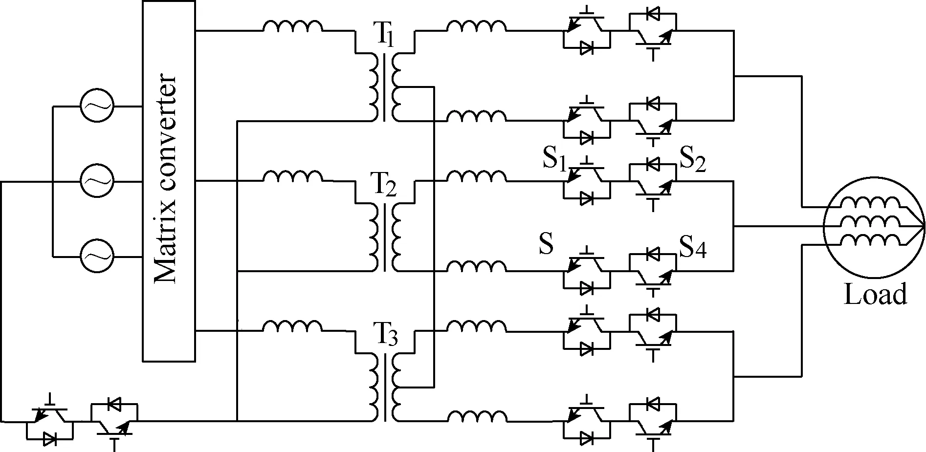
Fig.4 Three-phase matrix topology of PET

Fig.5 AC-DC-AC topology of PET
According to Eq.(2), the efficiency estimation expression can be obtained as:

From Eq.(7), it can be concluded that the efficiency of this topology is low because it has more power conversion links than the AC-AC-AC topology of PET.
3.6 Dual DC link PET
In order to solve the problems of the AC-DC-AC topology of PET, the AC-DC-AC-DC-AC dual DC link topology of PET is proposed. The system frame diagram is shown in Fig.6. First of all, the input is rectified into three-phase DC voltage, and then, to achieve single-phase inverter transformation. Then, the voltage is coupled to the secondary side by the high-frequency transformer to realize the single-phase transformation of the voltage.Finally, three-phase inverter is utilized to obtain the required three-phase ac voltage[16].The circuit diagram is shown in Fig.7. Compared with the AC-DC-AC topology of PET, this topology adds two circuits for enhances the controllability. However, the circuit is difficult to realize and has some problems such as voltage-sharing of the switch.
According to Eq.(2), the efficiency expression can be obtained as:
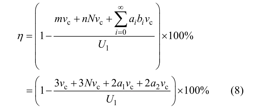

Fig.6 Dual DC link topology of PET system framework diagram

Fig.7 Dual DC link topology of PET
From Eq.(8), it can be concluded that, compared with the AC-DC-AC topology of PET, the dual DC topology of PET has lower efficiency and higher controllability.
4 Example: impedance network PET structure based on GaN and SiC devices
In view of the aforementioned problems, it can be concluded that the current PET topological structure still has the following problems that affect the efficiency and stability of PET, thus restricting the application of PET in industry and life:
● Large amount of electronic device. The topology of PET has many electronic devices, especially the number of switches. It will increase the loss of the transformer and reduce efficiency. At the same time, it will increase the control circuit and complexity of the system.
● Electronic device limitations. At present, more common full-control electronic devices are IGBT and MOSFET. Affected by the current technology, the corresponding high switching losses affect the overall efficiency of the transformer. Moreover,the corresponding voltage and current stress of these switches are limited and difficult to use for high-voltage and high-capacity occasions.
● Low voltage conversion ratio. The voltage conversion ratio of the traditional power transformer is limited by the turns ratio of the primary and secondary windings,which in turn affects the transformer size. The transformation ratio of PET is related to the buck-boost ratio of the buck-boost circuits. The current solution is to cascade multiple buck-boost circuits or to change the high-frequency transformer voltage conversion ratio. However, these solutions will increase the number of switches on the converter or increase its volume and complexity, so PETs efficiency has been affected.
● Low voltage and power level. The existing PET topologies have problems of low voltage and power levels due to the influence of maximum withstand voltage and current parameters of single switch. Only the MMC topology can realize high-voltage and high-power conversion.
● Low stability. A large number of switches cause the corresponding control circuits to be complicated.Moreover, electromagnetic interference of high power circuit will make the switch control turn on or turn off at mistakes, which will lead to the collapse of the whole transformer. Therefore, the stability of the converter is also one of the problems to be solved.
In view of the above problems, an impedance network topology of PET based on GaN and SiC electronic devices is proposed, and its frame structure is shown in Fig.8. The introduction of impedance network can realize single-pole high voltage transformer ratio,avoid switching tube shoot through and achieve isolation.The introduction of GaN and SiC devices can greatly decrease the switching power loss under high-power and large-capacity conditions, thereby greatly improving the efficiency of PET.
As showed in Fig.8, the impedance network and the matrix converter can be various types of impedance networks, and one of them is shown in Fig.9.
5 Conclusion
PET has received increasing attention from both industry and academia for applications in smart grid and the energy internet. In this paper, several typical PET topologies are modeled, analyzed and compared in detail.Then, current problems affecting PET efficiency and stability are summarized and corresponding solutions are derived. Finally, the corresponding scope of industrial applications for these topologies is identified, providing theoretical guidance for their industrial applications.

Fig.8 Impedance network PET structure based on GaN and SiC devices

Fig.9 A circuit diagram of impedance network three-phase matrix PET based on GaN and SiC electronic devices
 Chinese Journal of Electrical Engineering2018年2期
- Chinese Journal of Electrical Engineering的其它文章
- Brushless Doubly-Fed Machines:Opportunities and Challenges
- Control and Applications of Direct Matrix Converters: A Review
- An Optimal Charging/Discharging Strategy for Smart Electrical Car Parks
- Two-Stage Transformerless Dual-Buck PV Grid-Connected Inverters with High Efficiency
- A New Active Gate Driver for MOSFET to Suppress Turn-Off Spike and Oscillation
- Dual-Coupled Robust Wireless Power Transfer Based on Parity-Time-symmetric Model
