Comparison of the Back-Stepping and PID Control of the Three-phase Inverter with Fully Consideration of Implementation Cost and Performance
(School of Electrical and Electronic Engineering, Nanyang Technological University, Singapore)
Abstract: The three-phase inverter with LC filter has been widely applied in many industrial areas,mainly for non-connected grid utilization. Meanwhile, the standard of power quality needed in industrial applications tends to grow as time goes by, requiring more advanced and economical control strategies to fulfil this objective without comprising the stability of the system. For this reason, a comparative study of Back-stepping control strategy and PID control method are presented in this paper,based on an unconnected-to-grid three-phase inverter with LC filter. The control purpose is to produce sinusoidal load currents with amplitude and frequency fixed by a reference signal, where both steady state performance as well as transient performance are examined and compared, with fully consideration of implementation cost. Two controllers have been built in a Matlab/Simulink environment, where Park transformation (abc/dq0) and bipolar Sinusoidal Pulse Width Modulation(SPWM) strategy are implemented. For validation, hardware verification is also presented based on dSPACE DS1103 control-based prototype.
Keywords: Steady state, SPWM, dynamic, PID control, back-stepping control, THD, comparison.
1 Introduction
Nowadays, the application of the three-phase inverter has tremendously shaped people’s daily life, resulting from the a variety of technologies, for instance,renewable energy generation, electric vehicles, energy storage system, wind and solar power generation, micro grid, motor drive, fuel cell, and high voltage alternating current transmission(HVAC) system[1-3].
With new generations of power electronics emerging,including IGBT, MOSFET, and wide-bandgap devices made from GaN and SiC, the capability of three-phase inverter has grown as well. Higher switching frequency as well as breakdown voltage enables the three-phase inverter to be applied to DC-AC systems at different voltage levels in various occasions. As a result, control of the three-phase inverter tends to grow tougher when faced with voltage fluctuations, parameter perturbations,and load disturbances[4]. Meanwhile, the standard of power quality needed in modern industrial systems tends to grow, consisting of high stability, strong robustness,low total harmonic distortion(THD), satisfactory transient and steady-state performance[3-5]. To this end,finding an effective as well as economic control method implemented in the three-phase system that can guarantee pleasing steady and transient performance without sacrificing the stability of the system is of great significance.
To fulfil the stability requirement for the threephase inverter system with LC filter[6], a list of control theories have been put forward in the past few decades.These control strategies mainly belong to two categories,namely linear control methods and nonlinear control ones[7-9]. Specifically, this paper is focused on the derivation of two-step back-stepping control method based on Lyapunov criterion, as a representative for the nonlinear control category. Traditional PID control method is also studied, as a typical representative control method of linear control category, based on the Nyquist criterion.
By investigating the strengths and shortcomings of these two methods, this paper’s intention is to find a hybrid method that bridges the gap between linear control method and nonlinear control method where the merits of Back-stepping control strategy and PID control method can be combined. The overall structure of this three-phase inverter system implemented with two controllers is depicted in Fig.1.
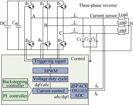
Fig.1 Overall structure of this three-phase inverter system combined with Back-stepping controller and PID controller
For PID controller, to find the optimal proportionalintegral-derivative(PID) gain is the main challenge[10-11].Only if these three parameters are tuned, would it be possible to achieve a satisfactory quality of output. To realize this objective, a couple of methods have been proposed, among which Ziegler-Nichols(Z-N) method[12]was widely accepted, since it has been applied in practice in designing estimators and PID controllers for various control needs. [10] introduced a mathematical way to calculate Kp, Ki, Kd. However, the applicable scope of this method is confined to single- phase inverter.
In this paper, a new approach to tune Kp, Ki, Kdis discussed based on the mathematical modelling of the three-phase, aiming to eliminate the poles of closed-loop transfer function of inverter after Park transformation[13-14],where the coupling terms between d frame and q frame need can never be negligible when calculating the transfer function.
Backstepping control method can realize the stability of the three-phase-inverter system based on the Lyapunov criterion[5]. In [10], a mathematical backstepping derivation process has been done on the objective of finding the approach to control a singlephase inverter. However, this method is not applicable to three-phase inverter system directly. In this paper, a novel adaptive back-stepping controller was studied,where two-step derivation process have been displayed on d frame and q frame respectively based on the mathematical modelling of the three-phase inverter system. With coupling between d frame and q frame considered, the derivation process is much more onerous compared to that in [15-17].
Furthermore, two controllers have been built respectively in Matlab/Simulink environment, where Park transformation(abc/dq0) and bipolar Sinusoidal Pulse Width Modulation(SPWM) strategy are implemented.For validation, the open-loop and closed-loop hardware verification of both PID controller and back-stepping controller will be conducted based on dSPACE DS1103.Their experimental results will then be presented and compared as well, based on a real 500W three-phase inverter with 10 kHz switching frequency.
Finally, according to simulation results and hardware verification results, comparisons between two controlling approaches will be summarized, mainly focused on their implementation cost and performance.
The rest of this paper is organized as follows: the mathematical modelling of the three-phase inverter with LC filter is presented in Section 2. In Section 3, the derivation process as well as controller design details of two controllers are proposed. Simulation results and experimental verifications are illustrated in Section 4 and Section 5 summarizes this paper.
2 Modeling of the three-phase inverter with LC filter
2.1 Mathematical modelling in stationary coordinate
According to block diagram of the system depicted in Fig.1, the state variable equations can be figured out based on laws KCL and KVL, given by [15-17]:

where ia, ib, icdenote the currents flowing through the inductors, ua, ub, ucsignify the output voltages of inverter, isa, isb, iscstand for the load currents, and the load voltages are expressed as usa, usb, usc.
Since the loads are balanced three-phase resistance loads, the three-phase inverter is working in balanced state. That is to say, this system can be regarded as three single-phase systems to some extent. Fig.2 shows the block diagram of the A-phase current closed loop.
2.2 Mathematical modelling of three-phase inverter in rotating d-q frame
Three-phase AC signals are converted to two DC elements, implemented with dq0 transformation(Park transformation), since it is much easier and accurate to regulate two DC elements compared to AC components.The Park transformation matrix is given by:
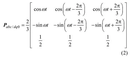
Since the loads are balanced three-phase resistance loads, which means that the element in 0 frame is zero.So Park transformation in system can be simplified as:

Hence, when Park transformation is implemented to(1), we can get the state variable equations in d-q frame:


Fig.2 Block diagram of the A phase
Considering the fact that matrix of Park transformation is unitary orthogonal matrix, its matrix can be expressed as:Therefore


Do the following replacement for the convenience in derivation process in Section 3.

Substitute (7) into (4), we can get

3 Back-stepping controller design
Back-stepping control strategy aims to make the subsystem stable, proceeding with steps to use the next state to drive to the control needed to stabilize, until the final control equation can be found[18-21]. The two-step derivation process is divided into d frame and q frame respectively. In Fig.3, it shows the General two-step derivation process of Back-stepping strategy in d frame.
3.1 d frame
3.1.1 Step one
Tracking error is defined by:

Its dynamics is given by:

Define the Lyapunov candidate function:


Fig.3 General two-step derivation process of Back-stepping strategy in d frame
With the choice:

In Equation (25), is a positive constant.

Up until now, the global asymptotic stability based on the second Lyapunov criterion is achieved.
3.1.2 Step two
To signify the difference between virtual value and its desired one, we can define a new variable error, given by:

Namely,

Substitute (15) into (11):

Then, substitute (12) into (16):

The second Lyapunov candidate function is defined as:

So that:

With the choice:

We can get:

That is to say the stability of this system has been guaranteed based on Lyapunov criterion[22].
Equation (20) is the final controlling strategy implemented to control the d-frame component of the output current.
Based on this equation, d-frame back-stepping controller has been built in Simulink environment,shown in Fig.4.
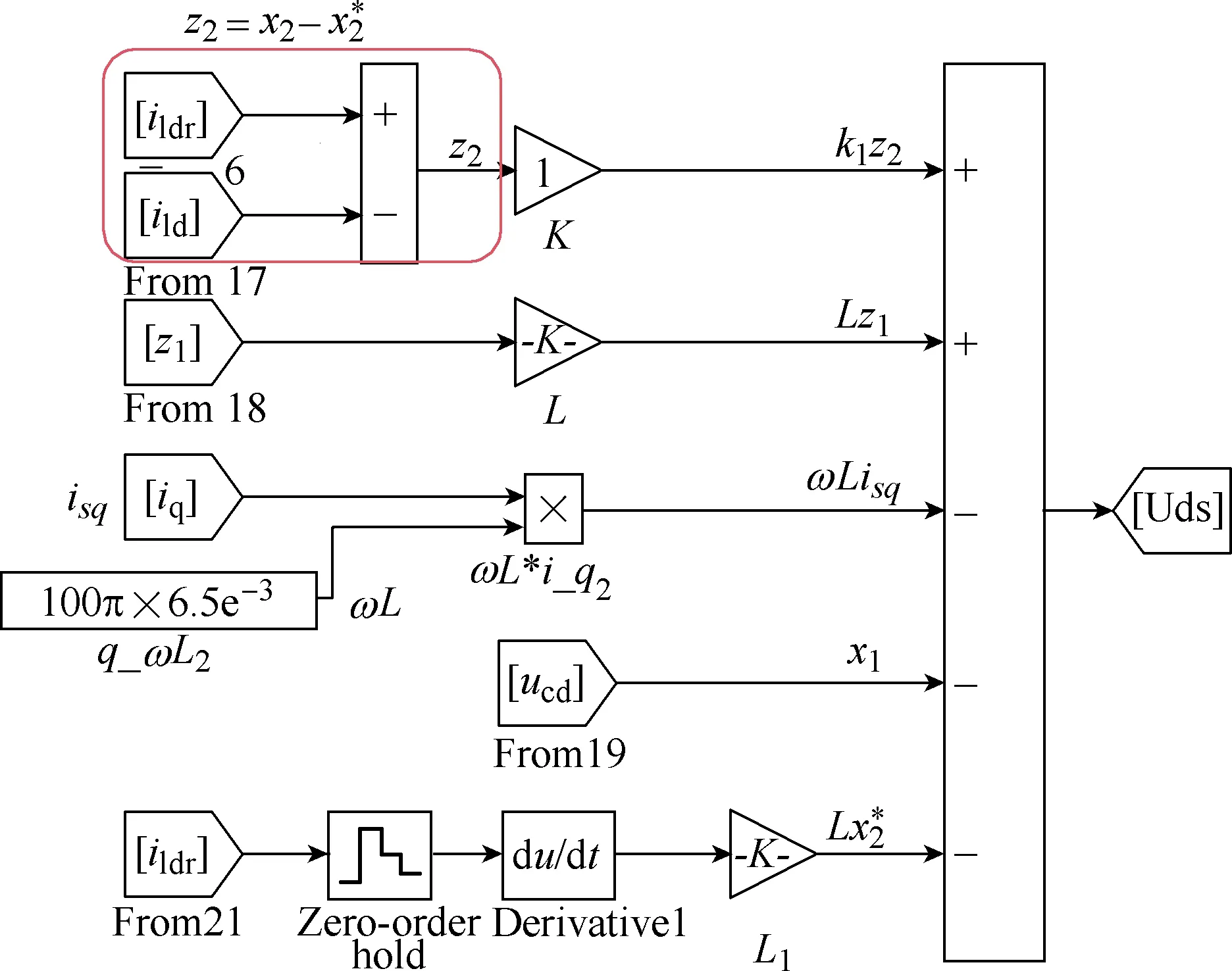
Fig.4 Back-stepping controller in view of d frame
3.2 q Frame
3.2.1 Step one
Tracking error is defined by:

Its dynamics is given by:

Define the Lyapunov candidate function:

With the choice:

So that

3.2.2 Step two
To signify the difference between virtual value and its desired one, we can define a new variable error,shown in equation 27:

Namely,

Substitute (28) into (24), we can get:

Then, substitute (28) into (29):

The second Lyapunov candidate function can be defined as:

So that:

With the choice:

We can get:

That is to say the stability of this system has been guaranteed based on Lyapunov criterion.
(33) is the final controlling strategy implemented to control the q-frame component of the output current. Similar to Back-stepping controller shown in Fig.3, the q-frame one can also be built in Simulink environment and has been omitted here.
4 PID controller design
By comparing the existing difference between the desired set point (SP or reference value) and the actual output of a controlled system, PID controller generates an error signal and aims to suppress it,based on its proportional gain, integral ability as well as derivative property[10-12].
4.1 Block diagram of the three-phase inverter in d-q frame
Based on (4), its block diagram can be built shown in Fig.5.

Fig.5 Block diagram of the three-phase inverter in d-q frame
According to (4) and Fig.5, it shows that id, iqare linked with both ud, uqand ωLid, ωLiq.
4.2 PID-values selection strategy (take d frame for example)
According to the block diagram shown in Fig.2,the closed-loop transfer function is given by [13-14]:

The control signal is generated by PID controller from the error ε(t),

His expression transmittance of Laplace:

That can also be written in this format:

The closed-loop transfer function, consisting of the transfer function of inverter and PID controller, is given by

The parameters, proportional gain, integral gain,derivative gain, are selected to eliminate the two poles of a closed-loop transfer function[10], so that,

Then, the closed-loop transfer function will be simplified as:

Here, Kpis set manually according to the control objective desired. Once the value of Kphas been set,the values of Ki, Kdcan be figured out based on equation 40.
5 Simulation and experimental verification of back-stepping controller and pid controller
5.1 Simulation results and analysis
System parameters in Simulink model are summarized in Table 1.

Table 1 Specifications of simulink model

Fig.6 Simulation results about load currents of PID controlled loop


Fig.7 Simulation results about load currents of Back-stepping controlled loop
5.2 Experimental verification
In Fig.3 it shows the overall structure of the experimental testing configuration. When the DC side of the inverter is set to 50 volts and the load is set to 10Ω,the three-phase inverter will have 90-watt real power.

Fig.8 Experimental test platform
5.2.1 Back-stepping controller
● Steady state


Fig.9 Waveforms of load currents in steady state when Back-stepping controller is implemented
● Transient response when current reference changed
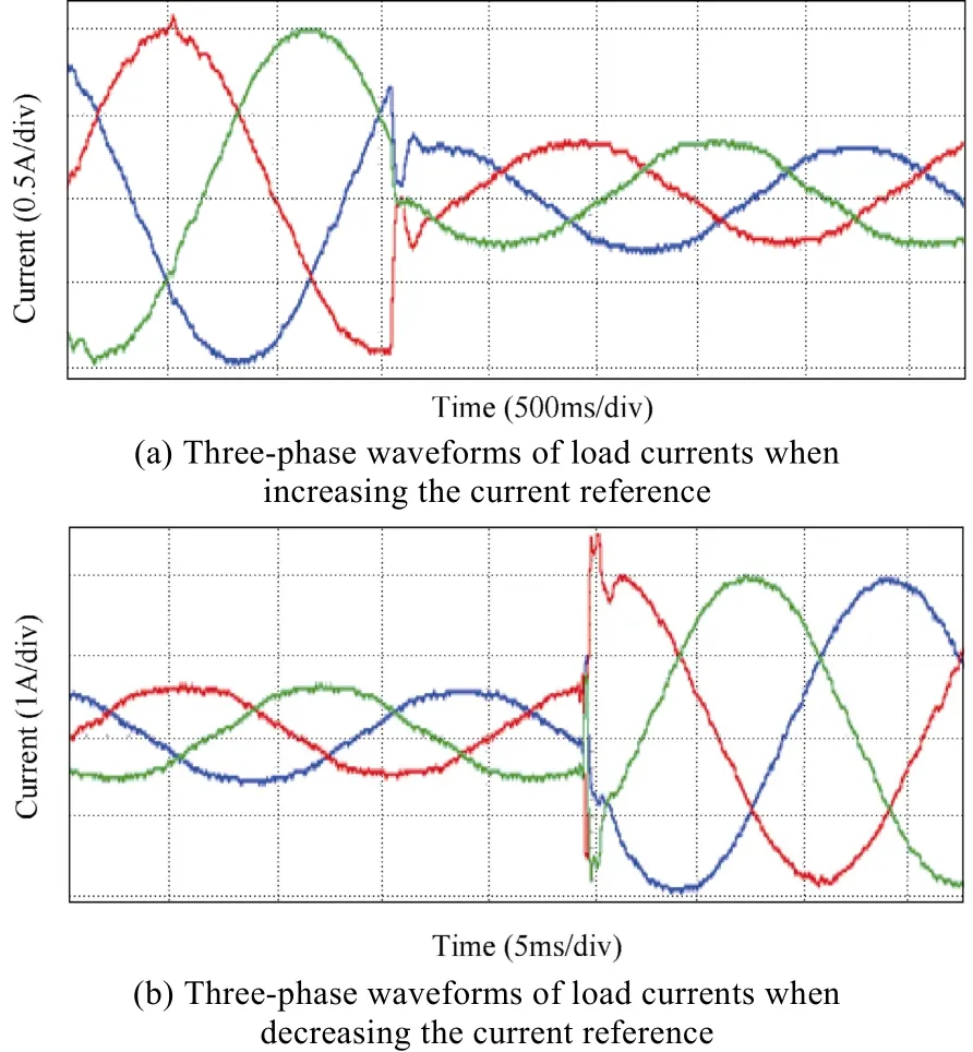
Fig.10 Waveforms of load currents in transient state when Back-stepping controller is implemented
5.2.2 PID controller
● Steady state

Fig.11 Waveforms of load currents in steady state when PID controller is implemented
● Transient response

Fig.12 Waveforms of load currents in transient state when PID controller is implemented
● Critical stable
Increase the values of Kp, Ki, Kd, upper saturation limit and lower saturation limit, until the PID controller can track the reference current at highest speed,meanwhile recorder these parameters in Table 2.
Fig.13 shows how loads currents track the current reference with sudden load changes, where the waveforms begin to become unbalanced, with more harmonics emerging as well. If the parameters continue to increase, this system will become unstable.
6 Conclusion
Based on simulation results as well as hardware verification, comparisons between PID control method and Back-stepping control method have been summarized in Table 3.
PI control strategy can be applied to guarantee the stability of the three-phase inverter based on Nyquistcriterion. Direct-quadrature-zero transformation (dq0 transformation) was implemented before the designing process of the PI controller, which greatly simplified this process and enhanced PI controller’s effectiveness, since it is much easier and more accurate to control two DC components compared to three-phase coupling AC currents. With this advantage, the dq0 transformation was also used in back-stepping control design.

Table 2 Parameters of PID controller in critical stable condition
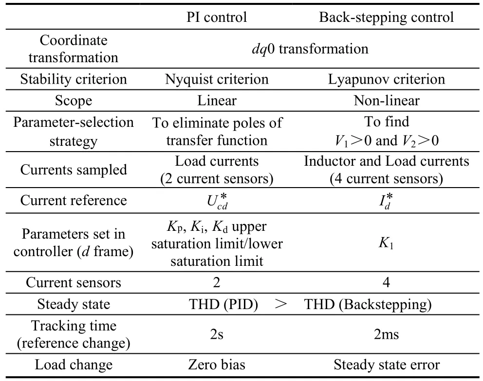
Table 3 Comparisons between two controllers
Back-stepping control scheme can guarantee the stability of the three-phase inverter, based on Lyapunov criterion. Two steps of back-stepping derivation were needed to find ideal Lyapunov function, at the same time,the final control strategy, namely, (33) was determined.In this process, the second step was actually based on the first step. In general, the steps needed to stabilize the origin of a certain class of nonlinear dynamical system are determined by the number of state variables in specific systems. For instance, this three-phase inverter system has two state variables, and the derivation process consists of equally two steps of back-stepping.
When it comes to two controllers’ parameterselection strategy, the procedure of PI controller seems to be much more brief and direct, for the reason that PI controller design is based on Nyquist criterion, in which process, only zeros and poles of transfer function need consideration. The parameter-selection objective of PI controller is to eliminate the poles of open-loop transfer function based on inverter modelling. While the design of back-stepping not only needs more complex inverter modelling process, but also two steps’ derivation, where finding the ideal Lyapunov function that can both guarantee its positive definite property and the negative semi-definite nature of its first order of time derivative is not an easy task.
For PI controller, only two current sensors were needed to sample A-phase current and B-phase current of load currents. The C-phase current can be derived by using zero to subtract the sum of the other two-phase currents, since the load is balanced resistance load. By doing so, the three-phase currents can be sampled by only two current sensors.
Admittedly, the specific parameters of the hardware components, such as loads, sensors, wires, may not be exactly the same, making the three-phase sampling signals’ amplitude unbalanced to some extent. After a laundry list of tests and measurements, this level of random errors is tolerable, showing negligible disturbance to the static stability and transient tracking performance of both PI controller and backstepping controller.
Compared to a PI controller, cost penalty should be laid on back-stepping controller, since the latter needs two times as many sensors as the PI controller. However,transient tracking experiment shows that this cost is well worthwhile to some extent because the tracking speed of back-stepping controller is 1000 times as fast as the PI controller, 2ms and 2s respectively, if we compare the experimental waveforms of load currents shown in Fig.10 and Fig.12. On the contrary, PI controller obviously outperforms the back-stepping controller in view of the steady state error if a sudden three-phaseload change occurs, based on the simulation results presented in Fig.6 and Fig.7.
To combine both PI controller’s great steady state performance and Backstepping controller’ s outstanding transient response, an intentional hybrid control strategy can be proposed: the q-frame load current is controlled by PID control strategy, while the d-frame current is regulated by back-stepping controller. This method will also reach a balanced point in terms of the number of current sensors needed. Moreover, whether this hybrid approach will possess our desired property waits to be seen based on both simulation and hardware verification.
 Chinese Journal of Electrical Engineering2018年2期
- Chinese Journal of Electrical Engineering的其它文章
- Brushless Doubly-Fed Machines:Opportunities and Challenges
- Control and Applications of Direct Matrix Converters: A Review
- An Optimal Charging/Discharging Strategy for Smart Electrical Car Parks
- Two-Stage Transformerless Dual-Buck PV Grid-Connected Inverters with High Efficiency
- A New Active Gate Driver for MOSFET to Suppress Turn-Off Spike and Oscillation
- Dual-Coupled Robust Wireless Power Transfer Based on Parity-Time-symmetric Model
