
Influence of Negative Pressure Gradient on Pressure Distribution and Gas-Solid Flow Pattern of Solid Feed Systems
2018-07-23 02:31ZhangMeijuPanFengShaoGuoqiangGeYuZhangLei
中国炼油与石油化工 2018年2期
Zhang Meiju; Pan Feng; Shao Guoqiang; Ge Yu; Zhang Lei
(State Key Laboratory of Multi-phase Complex Systems, Institute of Process Engineering,Chinese Academy of Sciences, Beijing 100190)
Abstract: A series of experiments on a solid feed system was performed to investigate the effect of negative pressure gradient on the gas-solid flow pattern and hydrodynamic characteristics. Based on the non-fluidized gas-solid two phase flow and particulate mechanics in the standpipe, a method for predicting the pressure of the air passing through the recycle chamber and the pressure drop through the loop seal slit in these systems is also presented. The predicted pressure profile along the negative pressure gradient from the proposed model exhibits a good agreement with the experimental data. The experimental data show that the gas flow in the standpipe is always upward in the negative pressure gradients, while the direction of gas cannot be changed by the drag force. The solid flow rate, the materiel bed height in the recycle chamber (Hf), the pressure drop across the slit (△Pg) decrease with an increasing negative pressure gradient. At a given negative pressure gradient,the superficial gas velocity through the recycle chamber of the loop seal does not affect the pressure drop in standpipe. It increases with an increasing negative pressure gradient.
Key words: fluidized bed; solid feed system; negative pressure gradient; gas-solid flow pattern
1 Introduction
Fluidized beds technology have been commercially utilized in numerous gas-solid contact processes, such as the fluid catalytic cracking (FCC), the circulating fluidized bed (CFB) boiler, the fluid-bed coal gasification,the Fischer–Tropsch synthesis in SASOL’s syncrude process, the oxidation ofn-butane to maleic anhydride,the calcination of aluminum hydroxide to high-grade alumina[1-2], etc. The solid particles entering the fluidized bed reactor have to overcome the negative pressure gradient, that is a process of transporting solids from the lower to the higher pressure points. For applications under the elevated temperature and pressure conditions, a solid feed system usually consists of a standpipe and a loop seal. The solid feed system provides solid transfer and gas seal against the undesirable flow direction, and regulates the solid circulation rate. It has been reported that the major problem in CFB operation is the interruption of solid feeding or transfer of particulate solids[3]. The standpipe is known to exhibit a rich variety of flow behavior, and it is known to experience instability under certain operating conditions, which can lead to inadequate pressure buildup in the pipe[1]. Therefore, the proper operation of a solid feed system is crucially important for the safe and stable operation of the fluidized bed reactor[4].Sung Won Kim, et al.[3]verified that the pressure drop increases with a decreasing particle size and an increasing particle density in the vertical aeration section. Jing Shan[5-6]studied the characteristics of the hung-up regime for powder in a hopper-standpipe system and described the incipient condition of hung-up regime. Wang, et al.[7]reported that the solid flow rate increases with an increasing aeration rate, while the solids offer a drag force to drag the air flow downward with them. The direction of gas flow in standpipe is not consistent with the data published by other researchers. Butler, et al.[8]found that air flows upwards when solid recycling is just started,but then a reversal takes place after which air is dragged downwards in a wide aeration range. Data from Yao, et al.[9]revealed that air always flows downwards untilGsreach a maximum solid flow rate of the system. Previous researchers have strived for exploring the basic principle of loop seal operation and the parameters affecting the solid flow. These investigations improve greatly the understanding of the flow characteristics of the powder in a solid feed system. However, the researches about the influence of negative pressure gradient are comparatively sparse, and the directions of gas flow in standpipe are diversified. It is therefore necessary to investigate the influence of the negative pressure gradient on the pressure distribution and the gas-solid flow patterns of solid feed systems.
In the present study, the gas-solid flow behavior and hydrodynamic characteristics in standpipe were investigated in a bid to understand the hung-up regime mechanism, the pressure distribution, and the control method.
2 Experimental
The solid feed system, which was made of transparent Plexiglas for easy observation, included a hopper, a conical hopper, a standpipe (0.07 m in i. d. × 2 m in height), a loop seal and a solids collector, as shown in Figure 1. The loop-seal had a rectangular cross-section,0.10 m in width, 0.215 m in length, and 0.51 m in height.It consisted of a supply chamber (0.10 m×0.10 m)connected to the standpipe and a recycle chamber(0.10 m × 0.10 m). The two chambers were connected with a thin partition (0.015 m thick) with an opening of 0.03 m in height. The weir section was 0.235 m high.During the experiment, the loop seal operating air came from the wind boxes located under the supply chamber.Bed material was introduced into the system through a hopper linked to the standpipe. The solid particles from the hopper were transported into the standpipe through a loop-seal for regulating the solid flow rate by aeration prior to being fed to the receiving tank. Under normal operating conditions, three rotameters (0.1―1.6 m3/h),including one for recycle pipe and the others for the loopseal aeration, were used for controlling and measuring the gas flow rate. The time (t) and the weight of the cumulated powder in the receiving tank were measured,from which the solid flow rate could be calculated. A pressure sensor testing system was used to record the pressure signals. As illustrated in Figure 1, the interval of pressure taps was 100 mm on the standpipe, the location of the last pressure tap was 30 mm above the bottom of loop-seal. The height of solids in the recycle chamber (Hf)was measured simultaneously during the experiment. The fluidizing gas was air (20 °C, 101 kPa), with a density of 1.21 kg/m3and a viscosity of 1.79×10⁻⁵kg/(m·s). Glass beads were used as the solid particles, which had good fluidization ability. Table 1 shows the main physical properties of the glass beads.

Table 1 Physical properties of glass beads used in the experiments
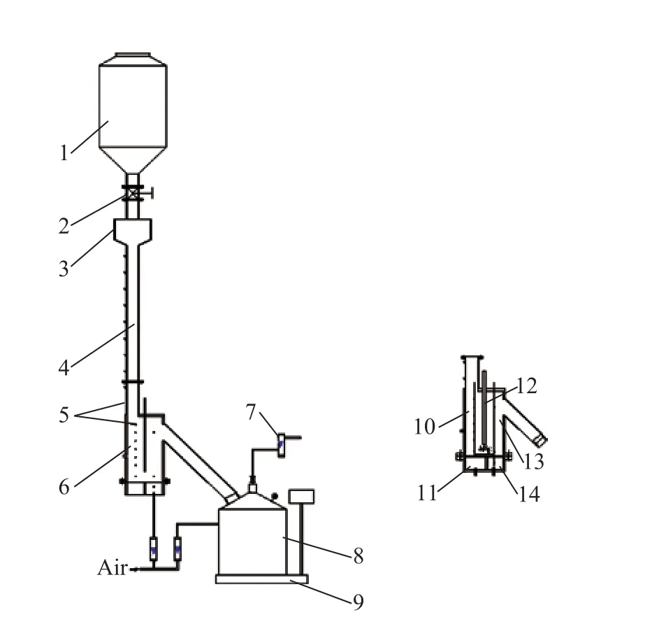
Figure 1 Schematic diagram of experimental apparatus
3 Results and Discussion
3.1 Experimental phenomena
The relationship between the solid flow rate (Gs), the negative pressure gradient (ΔP) and the experimental phenomena in the solid feed system is shown in Figure 2 and Figure 3, respectively. As shown in Figure 2, at a given superficial gas velocity (Ug) of 0.01556 m/s,0.01778 m/s, and 0.02 m/s, respectively, the solid flow rate decreased with an increasing negative pressure gradient. When ΔPwas close to 7 kPa, some upward bubbles appeared in the moving-bed standpipe to reduce the velocity of particles in experiment. When ΔP=14 kPa,the stable bubbles bridged the entrance of moving-bed standpipe and hindered the flow of particles in the hopper(when the particles were hung up above the standpipe)as shown in Figure 3. In order to find the cause of this phenomenon, the effect of the negative pressure gradient should be studied in detail.

Figure 2 Effect of ΔP on Gs

Figure 3 Experimental phenomena
3.2 Pressure drop in the standpipe and supply chamber
Figure 4 shows the pressure drop at different superficial gas velocity (Ug) when the negative pressure gradient is 13 kPa. It suggests that the pressure drop is essentially the same at a given negative pressure gradient. This means that the superficial gas velocity through the recycle chamber of the loop seal does not affect the pressure drop of standpipe. As we know, the solid particles in the standpipe are a moving packed bed during transport at a negative pressure gradient. The pressure drop in standpipe is the result of the fluid particle friction in moving beds. Since the leakage of gas to the supply chamber is constant at a given negative pressure, the fluid-particle friction remains constant. Therefore, the pressure drop in the standpipe remains essentially at the same value.
It has been found that the operation of the loop seal is much dependent on the air flow rate of the loop seal aeration of the recycle chamber, and a stable operation can only be achieved above its critical value. In Figure 5, the superficial gas velocity through the recycle chamber was 0.0178 m/s.With no air flow passing through the supply chamber, the experimental value of pressure drop decreases with an increasing value of height at a given negative pressure gradient. On the contrary, the value of pressure drop increases with an increasing negative pressure gradient.That means, the leakage of gas to the supply chamber increases with an increasing negative pressure, and the fluid-particle friction also increases, leading to the increase in the pressure drop in standpipe. In addition, during the process of gas leakage along the standpipe, the amount of gas will decrease gradually because of the entrainment effect of the down-going solid particles.
The conventional sealing ability denotes the maximal negative pressure gradient with which the moving bed can be loaded. The theoretical sealing ability of a moving bed is equal to the bulk density of the solid particles, the theoretical sealing ability of standpipe can be estimated by the following equation[10]:

The calculated results are shown in Figure 5. When the negative pressure gradient lies within a range of 0-13 kPa,the pressure drop of standpipe at each point is less than the theoretical sealing ability. The feed system can transport the solid particles normally. When ΔP=13 kPa, the pressure drop is higher than the calculated value, and the theoretical sealing ability is broken up in the supply chamber.According to Kuo and Soon[11], there exists a critical value of negative pressure gradient for a countercurrent co-gravity moving bed, which is less than the theoretical sealing ability. When the negative pressure gradient exceeds the critical value, the moving bed becomes unstable. The critical value is 13 kPa in the feed system.

Figure 4 Pressure drop versus height at different gas velocity of feed system

Figure 5 Pressure drop versus height at different negativepressure gradient
3.3 Effect of negative pressure gradient on the pressure of recycle chamber air box
At a fixed superficial gas velocity of 0.0178 m/s, the effect of negative pressure gradient on the pressure in the recycle chamber air box (Pr) is shown in Fig 6. As it can be expected,Princreases with an increasing ΔP. The density of gas increases with the increase of pressure and the higher buoyancy force originating from the higher density air under higher pressures makes it easier to support the weight of the particles at a higher ΔP.Prand ΔPshow a significant linear relationship. Therefore, the fitting formula can be obtained as follows, with the correlation degree of the formula (R) equating to 0.9996.

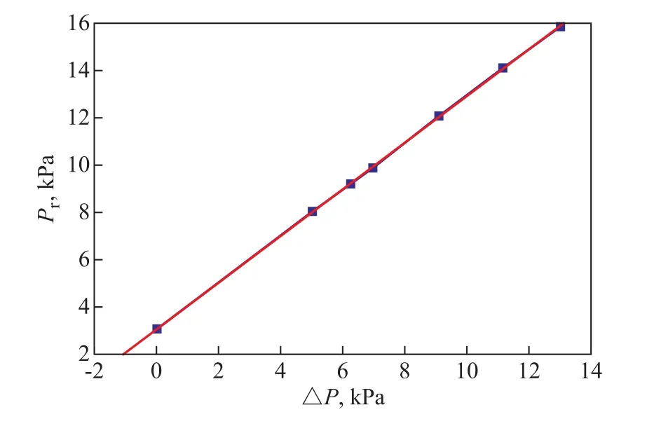
Figure 6 Pressure of recycle chamber air box versus the negative pressure gradient
The calculated values agree well with the measured ones in the tests. Correspondingly, the values ofPrcan be calculated by Eq. (2). It shows that the model can be applied to estimate the pressure of recycle chamber air box through the loop seal under different negative pressure gradient.
3.4 Pressure drop across the loop seal slit opening
Solid particles from the supply chamber flow into the recycle chamber through an aperture or slit in the partition between these two chambers. The pressure drop across the slit is similar to that between two side-by-side fluidized beds. The influence of ΔPon the pressure drop across the slit ΔPgis presented in Figure 7, showing that the pressure drop across the slit decreases with an increasing negative pressure gradient at a given superficial gas velocity of 0.0178 m/s. Meanwhile, the decrease of orifice pressure drop reduces the driving force of solid particles for passing through the orifice. And the sealing ability of particles beside the loop seal slit decreases with an increasing negative pressure gradient. The velocity of particles entering the recycle chamber decreases too. This can explain why the solid flow rate decreases with an increasing negative pressure gradient in Figure 2. Furthermore, this experimental phenomenon can also be explained by Eq. (3).Chong Y. O., et al.[12]suggested the following equation for the solid discharged through the valve.

whereGsis the solid flow rate based on the cross-section of loop seal,Cdis the aperture discharge coefficient,Ais the area of aperture,ρsis the solid density, andεmfis the minimum fluidization voidage. In Eq. (3) the parameters(Cd,A,ρsandεmf) can be regarded as constants, and thenGsdecreases with a decreasing ΔPg. According to the experimental data in Figure 7, the fitting formula can be obtained as follows at a correlation degree (R) of 0.98782.

Eq. (4) is more suitable for ΔPthat is less than 14 kPa.
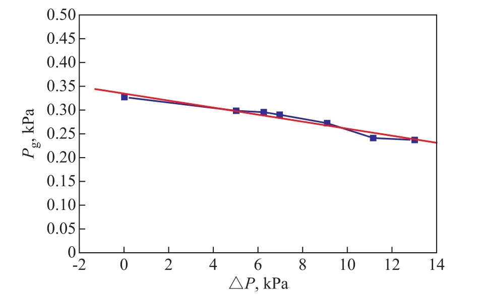
Figure 7 Pressure drop across the slit versus the negative pressure gradient
3.5 Gas flow rate in the standpipe
The pressure in standpipe is formed due to the difference in velocity of the solid phase and the gas phase, namely the slip velocity. The slip velocity (Usl) is defined as

The total energy loss in the standpipe, in which the solids move slowly as a moving packed bed, can be treated as the sum of viscous and kinetic energy losses[4]. The frictional pressure drop per unit length can be expressed by the Ergun equation as a function of

whereεis the voidage in standpipe[14]. The velocity of particles in standpipeUscan be calculated as

With the known values of ΔP,Gs, and particle properties,Usgin the standpipe can be calculated from Eqs. (5), (6),and (7). The positive value indicates the downward flow and the negative value represents the upward flow ofUsg.The effect of negative pressure gradient on gas velocity in the standpipe is shown in Figure 8. The absolute value ofUsgincreases with an increasing ΔPat a given superficial gas velocity of 0.0178 m/s. It indicates that the gas flow rate increases and more gas can get into the standpipe. The value ofUsgis negative, which means that the gas flow behavior in the standpipe is upward at a negative pressure gradient. The direction of gas cannot be changed by drag force and is opposite to the solid motion in the standpipe.Since a part of gas can get into the standpipe, the air flow rate through the space around solid particles in the recycle chamber is reduced. Therefore, the solid flow rate reduces because of the decrease in the fluid particle friction.
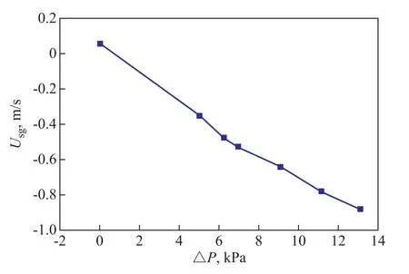
Figure 8 The effect of negative pressure gradient on gas velocity in the standpipe
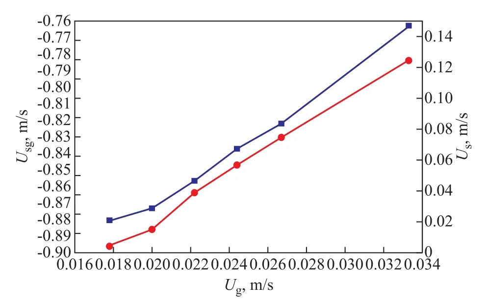
Figure 9 The gas velocity and solid velocity in the standpipe versus superficial gas velocity
Figure 9 shows the gas velocity and the solid velocity in the standpipe at different superficial gas velocity values when ΔPis 13 kPa. As it can be expected, the absolute value ofUsgdecreases and the solid velocity(Us) increases with an increasing superficial gas velocity(Ug). Since the solids moving downward can offer a drag force to drag the air flow downward with them, higherUsincreases the fluid particle friction (gas-solid drag force),which can decrease theUsg.
3.6 Effect of negative pressure gradient on bed expansion height
If the materiel bed height in the recycle chamber is higher than the height of recycle pipe, the loop seal can discharge normally. At a fixed superficial gas velocity of 0.0178 m/s,the effect of negative pressure gradient on the materiel bed height in the recycle chamber (Hf) is shown in Figure 10. As it can be seen,Hfdecreases with an increasing negative pressure gradient. That is whyGsdecreases with an increasing negative pressure gradient. When ΔPis 14 kPa,Hfis 23.3 cm which is lower than the outlet height of 23.5 cm. Therefore, the solid flow rate becomes zero.
This phenomenon can be explained by following aspects:(1) Because a part of gas can get into the standpipe, the air flow rate through the space around solid particles in the recycle chamber is reduced; and (2)Hfdecreases with an increasing ΔP. WhenHfis less than the outlet height,the solid flow rate in the loop seal will be interrupted.
In order to optimize the flow characterization of powder in a feed system with negative pressure gradients, the height of recycle pipe should be reduced during the design of loop seal. In addition, a special structure should be set up to decrease the gas quantity in the standpipe.
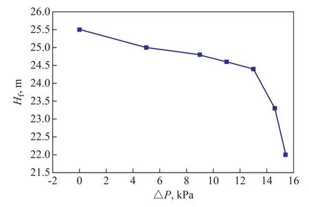
Figure 10 The effect of negative pressure gradient on bed height in the recycle chamber
4 Conclusions
In this work, the flow characteristics of solid powder in a feed system with negative pressure gradient were investigated at various negative pressure gradients. The gas−solid flow behavior in the standpipe has been studied.Based on the non-fluidized gas-solid two phase flow and particulate mechanics in standpipe, the following results were obtained:
(1) The solid flow rate (Gs), the materiel bed height in the recycle chamber (Hf), and the pressure drop across the slit (ΔPg) decreased with an increasing negative pressure gradient.
(2) At a given negative pressure gradient, the superficial gas velocity through the recycle chamber of the loop seal did not affect the pressure drop of standpipe. It would increase with an increasing negative pressure gradient. A method for predicting the pressure of the air through the recycle chamber and the pressure drop through the loop seal slit in these systems was also presented.
(3) The gas flow behavior in the standpipe was always upward in the negative pressure gradient. Although solid particles could make some gas go downward, the direction of gas could not be changed by the drag force.

- 中国炼油与石油化工的其它文章
- Denitrification of Coal Tar Diesel Fraction by Phosphate Imidazolium Based Polymeric Ionic Liquids
- Development and Application of Hydrocracking Catalysts RHC-1 /RHC-5 for Maximizing High Quality Chemical Raw Materials Yield
- Study of Isothermal Equilibrium, Kinetics and Thermodynamics of Adsorptive Desulfurization on Synthesized CuIYIIIY Zeolite
- Direct Conversion of Glucose to 5-Hydroxymethylfurfural over Zirconium Phosphate Catalyst in a Biphasic System
- Mass Transfer Characteristics of H2 and CO in Mimicked F-T Slurry Bubble Column Reactor
- An Approach for Preparation of Excellent Antiwear PTFE Nanocomposites by Filling As-prepared Carbon Nanotubes/Nanorods (CNT/CNR) Mixed Nano-Carbon Material