Investigating the flow characteristics of air-lift pumps operating in gas-liquid two-phase flow☆
Zhineng Wang,Yong Kang,Xiaochuan Wang*,Deng Li,Dong Hu
Key Laboratory of Hydraulic Machinery Transients,Ministry of Education,Wuhan University,Wuhan 430072,China Hubei Key Laboratory of Waterjet Theory and New Technology,Wuhan University,Wuhan 430072,China School of Power and Mechanical Engineering,Wuhan University,Wuhan 430072,China
1.Introduction
Airlift pump consists of a vertical pipe divided into two parts:suction pipe which is the part located between the air injection point and the bottom of the vertical pipe,riser pipe which is the part located between the air injection point and the top of the pipe.The main advantage of this pump is that it has no mechanical transmission and no necessary lubrication.Due to its simple construction,airlift pump is a low-cost tool for lifting corrosive,explosive and toxic materials in chemical industries[1]and is being used for other applications,including petroleum exploration,deep-sea mining,sewage treatment,and aqua farming pools[2].
Most of current researches were conducted to investigate the performance of airlift pump by measuring the output water at different air flow rates.It could be concluded that there are three aspects affecting the pumping performance:geometrical parameters,operating parameters and air injection methods.Mahrous[3]gradually enlarge the riser tube to reduce the acceleration loss and to minimize the transition to annular flow regime.He claimed that gradually enlarging the riser tube diameter at a position near the air injection zone would significantly increase the water flow rate.Kass ab[4,5]investigated the effects of submergence ratio on the performance of airlift pump for pumping coarse,irregular non-uniform particles.And he found that the mass flow rate of the solid particles increases as the submergence ratio increases at the same air flow rate.Ahmed[6,7]conducted a study to experimentally investigate the effects of air injection methods on the performance of airlift pumps.He designed some special air injectors enabling air injection radially,axially,dual and proposed a pulsating air injection mode at different injection frequencies.The results showed that the performance of airlift pumps with the pulsating axial injection operating at a frequency of 1 Hz has improved by 60%over that of typical steady axial injection.
In fact,all the above-mentioned investigations had optimized the performance of airlift pumps because they had improved the flow structure in airlift pump.However,the characteristics of this flow structure is difficult to be understand due to the complex combination of a water flow in suction pipe and a gas-liquid flow in riser tube.To further improve the performance of airlift pump,it is significant to investigate the flow characteristics in airlift pump.
In suction pipe,a second water stream is produced by the high speed air flow.The flow characteristic of this flow greatly affects inlet condition of airlift pump.Most of researchers conducted their experiments to investigate the frictional pressure loss caused by the pipe wall[8,9].The flow characteristic in suction pipe has not been studied yet.
In the riser pipe,water and gas phases are mixed together creating some complex flowstructures which directly determines the performance of airlift pump.For different flow structures,the drag forces acting on water are differentdue to the differentinter-facialareas and slip velocities.
A few researchers have investigated the flow structure in the riser pipe based on the flow pattern map in typical upward two-phase flow where both the air and liquid discharges are controlled.According to this map,Hana fizadeh[10,11]and Zaraki[12]used to infer that the flow structure in airlift pump experiences bubble flow,slug flow,churn flow,annular flow when slowly increasing the air discharge.Moisidis[13,14]and Tighzert[15]had further found that bubble flow was not observed even in an extremely low air discharge.In addition,it could be inferred from the typical flow pattern map that the annular flow will dominate the performance of airlift pump at high air flow rate.Thus,in theory of Stenning and Martin[16],the water flow rate will decrease sharply when continuing increasing the air flow rate in the annular flow regime,due to the thinner water film around the conduct.But based on experimental results of Kassb[4,5],Hu[17,18],Goharzadeh[19],the water flow rate almost remains constant even for a large air flow rate.It indicates that the flow structure in airlift pump is more complex than that in the typical upward two-phase flow.
In typical flow regimes,the flow regimes are determined by the flow rates ofgas and liquid.While,the flow rate ofliquid in airliftpumps pulsates strongly because the liquid is forced to flow by the drag force ofair flow rather than by the pumping force of a centrifugal pump.Thus,some new flow structures were usually found except the typical flow regimes.For example,Tramba[20]has observed a quasi-periodic burst-like behavior dominates the operation of the airlift pump in the riser tube under the conditions of low submergence ratios.
Considering the flow characteristics in suction pipe and riser pipe,many theoretical models of airlift pump were proposed for predicting the operation performance in three-phase flow.Kato[21]performed a study of a low-head airlift pump used to pump uniform particles.They developed the pump model based on the momentum equation and obtained its fundamental characteristics.Yoshinaga and Sato[8]developed a theoretical model based on the momentum equation proposed by Kato[21]and an empirical correlation of volumetric fraction from previous studies.Margris and Papanikas[22]also developed a model based on the equations of continuity and momentum.Even though these models may be used to predict the performance of airlift pump operating in two-phase flow by assuming the condition that no particle participatesin this flow.Abig error would exist bet ween the predictions and the actual values due to the differences between the frictional loss of two-phase flow and that of three-phase flow.
In the present work,a high speed camcorder and a Laser Doppler Velocimetry system(LDV)were employed to investigate the flow characteristics in the riserpipe and the suction pipe,respectively.Amodi fied model based on the momentum equation and two general empirical correlations of the frictional loss and the void fraction was developed to predict the performance of airlift pump operating in two-phase flow.
2.Experimental Setup
The experimental apparatus is shown in Fig.1.It mainly consists of a riser pipe(2100 mm),an air injector,and a suction pipe(600 mm).The entrance of a riserpipe wasconnected with the outlet of suction pipe by an air injector.The air injector used in this experiment was shown in Fig.2.It has two flanges which connected the riser pipe and suction pipe,respectively.The intermediate tank into which the suction pipe was inserted,was connected to a storage tank via an elastic tube.Both of the riser pipe and suction pipe had an inner diameter of 40 mm and were made of transparent plexiglass to visually observe the flow structure.Before the experiment,the submergence ratio,which was defined asγ=L/L2as shown in Fig.1,could be set by using the centrifugal pump to adjust the level of the water in storage tank.
The compressed air is continuously supplied by an air compressor and filtered by an air filter.To regulate the flow rate and prevent its fluctuation,a regulator and a shock absorber are mounted at the inlet of air injector.The air was injected into the injector and was merged into the water flowing through the suction pipe.Then,the two-phase gas-water mixture flowed upward in the riser pipe and discharged into the separator.In the separator,the air is separated form water and released to the atmosphere while the water continues flowing to the storage tank.To avoid the water fluctuation in the storage tank,a buffer tank is connected between the separator and the storage tank.In the process of the experiment,the submergence ratio almost remains constant since the outlet water is recycled.
In this experiment,the submergence ratio varied from0.3 to 0.7,and the air discharge varies from 0 to 60 m3·h-1.A gas turbine flow meter(type:LUGB25)with an accuracy of±1%was mounted near the air injector to getthe inlet air flow rate.A water flow meter(type:MAG25)with an accuracy of±0.5%was employed to get the water flow rate.

Fig.1.The schematic of airlift pump.

Fig.2.Air injector used in this experiment.
To observe the gas-water flow in vertical tube,a high speed camcorder(type:Phantom M310-12G)with 1500 frames·s-1was mounted at the location 1500 mm above the air injector.To obtain the characteristics of the water flow,a LDV is applied as shown in Fig.3.The LDV experimental setup in the present work is similar to that described by Liou et al.[23-25].Uncertainty in LDV measurement is within 12%.
3.Results and Discussion
3.1.Water flow rate
Fig.4 shows the results of the water flow rate(QL)as a function of the air flow rate(QG)at 6 submergence ratios(0.3,0.4,...,0.7).It could be seen that the water flow rate rapidly increases until it reaches its maximum beyond which the water flow rate almost remains constant despite the increased air discharge.This is consistent with the results of Kassab[4,5],Tighzert[15],Fan[26].
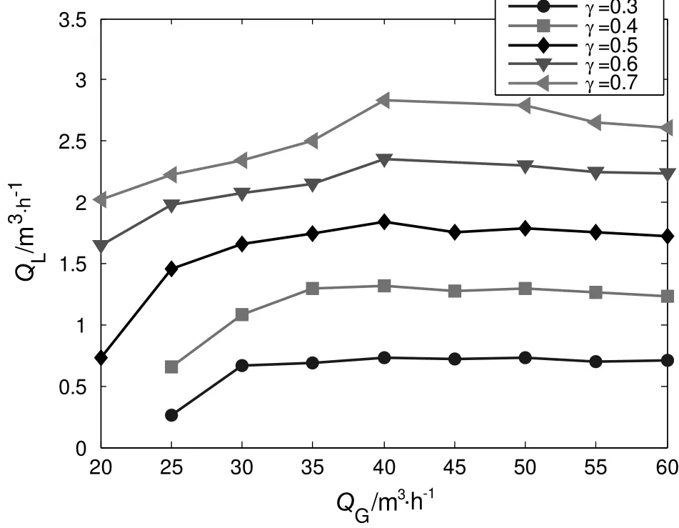
Fig.4.Water flow rate of airlift pump versus air flow rate at different submergence ratios.
The driving force to the water flow is related to the inter-facial areas in different flow regime.In the past research,most of former researchers considered that the flow structure in riser pipe successively experiences slug flow,churn flow,and annular flow with increasing air flow rate based on the typical flow pattern map.Moreover,slug flow is considered to be the best flow regime for pumping water due to most of water in liquid slug ascending and only a thin water film falling down.For churn flow,most of gas phase is in a form of gas core occupying the center of pipe which decreases the inter-facial areas.Thus,the output of water decreases due to the weak drag force.When operating in annular flow,only a thin water film ascending along the pipe.This kind of water film becomes more and thinner with the increasing air flow rate.Thus,Stenning and Martin[16]predicted that the water flow rate will decrease sharply when continuing increasing the air flow rate in the annular flow regime.However,the water flow rate almostre mains constantafter reaching its maximum when still in creasing the air flow rate as shown in Fig.4.In fact,the flow structure in airlift pump is much complex than that of typical flow in vertical pipe.From the video captured by the high speed camcorder,it could be found that gas appears in the form of continuous gascore and discrete bubbles,alternately.The discrete bubbles produce a large drag force due to its big inter-facial area,which prevents the decline of water flow rate.
Another phenomenon is that water flow rate increases with increasing submergence ratio which was also founded by Kassb[4,5],Hu[17,18].It has been confirmed that the high submergence ratio could improve the performance of airlift pump due to the high pressure gradient in riser pipe.
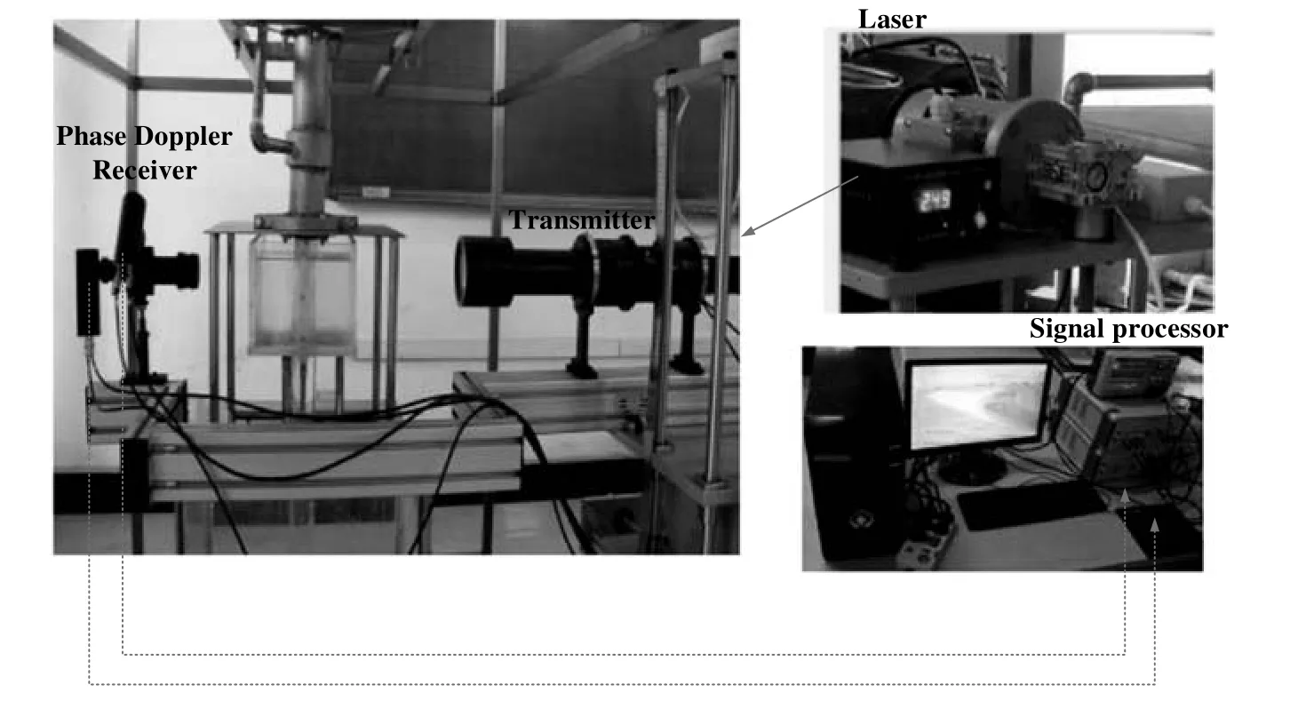
Fig.3.LDV measurement for the water flow in suction pipe.
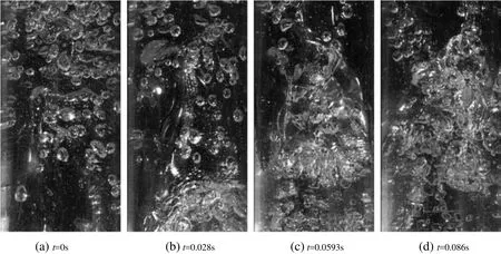
Fig.5.Photos of slug flow for Q G=20 m3·h-1 and γ =0.4.
3.2.Flow visualization results
To further investigate the performance of airlift pump,the flow structure in risertube wasobtained by using a high speed camcorder.When air lf ow rate is low(QG< 25 m3·h-1),a slug flow appears in the riser pipe.Fig.5 shows the sequence of slug flows for QG=20 m3·h-1and γ =0.4.A Taylor bubble mostly occupying about 90%of the central pipe appears in the view of Fig.5,while the water slug entrapped between the big bubbles is forced to move upward along the riser pipe.
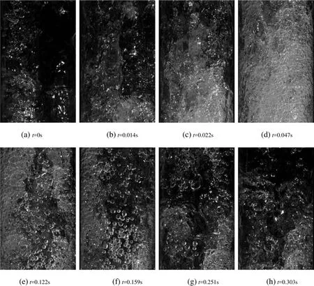
Fig.6.Photos of a cyclic flow process for Q G=35 m3·h-1 and γ =0.4.
When air flow rate is high(QG>25 m3·h-1),an unstable flow structure instead ofthe slug flow dominates the performance of air lift pump,as shown in Fig.6.The most dominant characteristic of this phenomenon is its cyclic nature.It mainly consists of three stages:water falling film,bubbly mixture,water ascending film.
(1)Water falling film.
Fig.6(a)shows a water film falling downwards along the inside wall of the conduit and an air core occupies most of the cross section of riser pipe.Few dispersed bubbles with a mean diameter about 2.4 mm were carried downwards along the riser.
(2)Bubbly mixture.
Fig.6(b-d)show a small spray region of a bubbly mixture.A high concentration of small bubbles scatters in the red circle of Fig.6(b).It could be seen in the Fig.6(d)that the small bubbles with a diameter in range of 0.2-0.4 mm almost make a linear motion with a high rising velocity of10-15 m·s-1.It produces a strong drag force to accelerate the water phase,due to the large inter-facial area and the high slip velocity between gas and water phase.
(3)Water ascending film.
Fig.6(e-h)show that the small bubbles are gradually absorbed into the air stream in the center of riser pipe while a new film with an upward velocity is formed along the inside wall of the conduit.The velocity of this water film is much lower than that of water phase in bubbly mixture because of the sharp decline of the quantity and velocity of small bubbles.As the time goes,the velocity of this film gradually decreases.When it decreases below to 0,a water falling film will be formed.
The unstable flow structure can be explained by the instability ofthe interface between the gas and liquid phases,as shown in Fig.7.
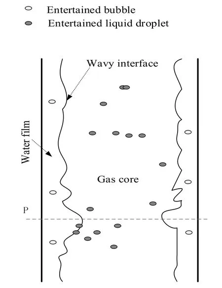
Fig.7.The interface between the gas and liquid phases.
According to the flow pattern map presented by Hewitt[27],the annular flow with a stable interface between gas and liquid phases could be formed in a typical upward gas-liquid flow at a high air discharge.However,the wavy interface between gas and water phase is extremely unstable in airlift pump because the liquid flow rate pulsates strongly.
When the velocity of water film decreases at location P,the thickness of this water film atthis location willsuddenly increases resulting in larger force acting on the interface due to an additional positive pressure.If the pressure on the interface is bigger than that in gas core,the interface ruptures.Therefore,the continuous gas core is discrete into a spray of small bubbles,as shown in Fig.6(e-f).However,the bubbles in bubbly mixture are easy to re-coalesce into a new gascore due to theirextremely short distance and huge number.Eventually,the recurrent interface fracture and reconstruction result in a cyclic nature of this flow structure.
The flow structure shows a characteristic of strong periodicity in the airlift pump.The flow cycle was defined as T.The duration of water falling film,bubbly mixture,water ascending film in one cycle of this flow structure could also be defined as t1,t2,t3,respectively.Similarly,their proportions of duration in the flow cycle could also be defined as:

These parameters could be estimated from the pictures captured by the high-speed recorder.Fig.8(a)presents the flow cycle as a function of the air flow rate.The higher air flow rate produces a smaller period.It indicates that the air discharge could increase the flow frequency.Except that,the submergence ratio also has a big effect on the flow period.The higher submergence ratio generates a longer period.It indicates that flow structure is more stable when increasing the submergence ratios.
Fig.8(b)shows the proportion of water falling film versus air flow rate for three submergence ratios(0.3,0.5 and 0.7).The proportion of water falling film decreases until it reaches to zero at air flow rate 45m3·h-1after which the water falling film doesn't appear in the riser pipe any more.The interface ruptures before the water film falling along the riser pipe.It could be expected that the interface becomes more fragile due to the decreasing pressure in the higher air flow.
Fig.8(c)shows the proportion of bubbly mixture versus air flow rate for three submergence ratios.It is obvious that this proportion in a range of 0.2-0.4 firstly increases to its maximum and then decreases slightly.Bubbly mixture is conducive to pumping water due to its capacity for accelerating liquid.Comparing with the curves in Fig.4,the trends of the proportion of bubbly mixture are similar with those of water flow rate.It could be inferred that the proportion of bubbly mixture directly determines the lifting water flow rate.
Fig.8(d)shows the proportion of water ascending film versus air flow rate.It could be seen that the proportion of water ascending film increases with increasing air flow rate.This is consistent with the flow pattern map made by Hewitt[27]that the higher flow rate promotes the formation of annular flow.
3.3.LDV results
LDV was employed to measure the velocity distribution in suction pipe.Fig.9 shows the characteristics of the water flow for two submergence ratios(0.4 and 0.5)at axial locations z=-200 mm(as shown in Fig.1).The average axial velocity(V)in a range of 0-0.45 m·s-1has a flat profile.In the central section of suction pipe(0.8R–R),the water velocity on this axis is slightly higher than that in the surrounding position.In the section closed to the wall,water velocity drops rapidly which is similar to the results of Liou[23].
For submergence ratio 0.4,0.5,both their water velocities in suction pipe reach to the irmaximumat QG=40 m3·h-1,which is also consistent with the water flow rate in Fig.4.As we know,the amount of air flow rate mainly changes the flow structure in riser pipe.When air flow rate is 40 m3·h-1,the proportion of bubbly mixture reaches to its maximum which produces a highest water velocity in riser pipe.To supply water for riser pipe,the flow rate in suction pipe also reaches to its maximum.
Fig.10 shows the velocity profiles for four submergence ratios(γ=0.4,γ =0.5,γ =0.6,γ =0.7)at axial locations z=-200 mm.It could be seen that the velocity increases with increasing submergence ratio.This is also consistent with the curves in Fig.4.For a large submergence ratio,the pressure in the suction pipe is higher which is more conducive to overcoming gravity of water.Another reason is that proportion of bubbly mixture increases which is also helpful for pumping water in suction pipe.
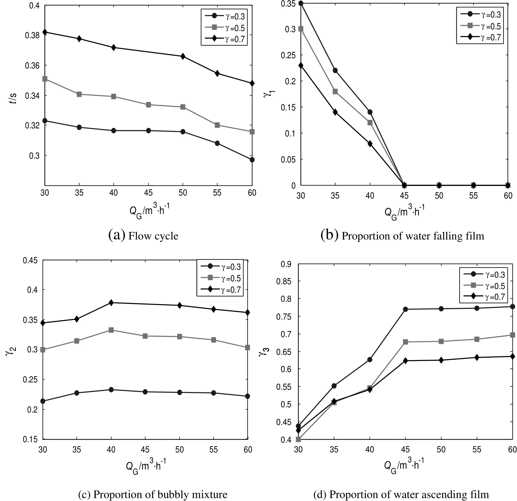
Fig.8.Flow parameters in riser pipe versus air flow rates.
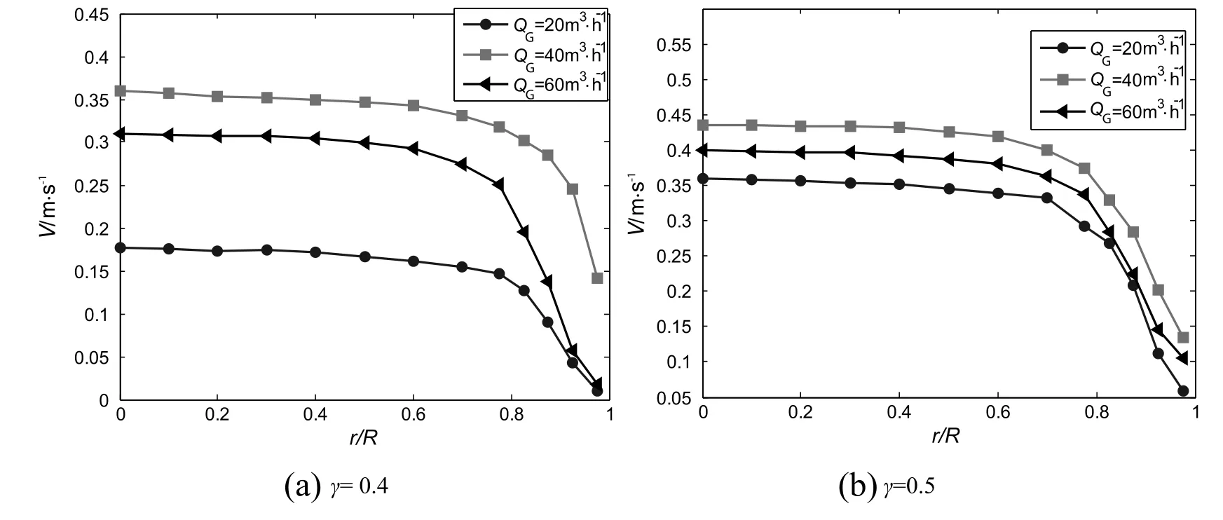
Fig.9.Measured average axial velocity profiles at γ=0.4 and 0.5.
Compared with Fig.10(a)and(b),it could be found that water velocity is very low at a low flow rate(QG=20 m3·h-1)and a low submergence ratio(γ=0.4).In Fig.10(a),the water velocity in suction pipe sharply increases when submergence ratio exceeds 0.4.As we know,slug flow dominates the performance of airlift pump.The length of liquid slug in riser pipe sharply grows up for higher submergence ratio.
3.4.A model for airlift pump
3.4.1.Momentum equation for airlift pump
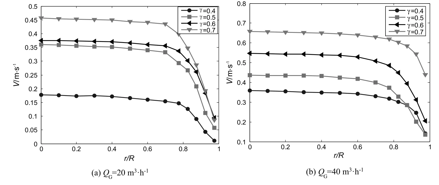
Fig.10.Measured average axial velocity profiles at QG=20 m3·h-1,and QG=40 m3·h-1.
There have been a lot of studies suggesting methods for the design model of an airlift pump lifting uniform particles[28].This kind of model was found to be able to predict the performance of airlift pump operating in three-phase flow.For airlift pump operating in the gasliquid flow,both the pressure drop and the void fraction are different with that in three-phase flow.To extend the operating range in gas-liquid flow,it is essential to develop a modified model for an airlift pump.
As shown in Fig.11,the airlift pump operating in two-phase flow consists of two parts:a riser pipe(IO)where a mixture flows and a suction pipe(EI)where water flows only.The symbols O,I,E denote the cross section of the riser outlet,the air injector and the water inlet.

Fig.11.Diagram of an airlift pump with the axial pressure distribution.

Most of early researchers(Kassab[4,5],Tomiytama[29])have employed the momentum for a control volume bounded by the pipe wall and the cross sections E and O.where J is the volumetric flow,τ the shear stress,ε the volumetric fraction,g the gravity acceleration,D the inner diameter of the riser,ρ the mass density,u the velocity.The subscripts G,L,GL represent gas,water and the gas-water mixture,respectively.
In Eq.(2),the first and second terms denote the momentum which enters through E and leaves through O.The third and fourth terms denote the frictional pressure loss in the water flow and in the two phase flow.The fifth and sixth terms denote the mass of water and the two-phase mixture.The seventh term denotes the pressure force of the surrounding water acting on E.
In the third term in of Eq.(2),the pressure loss in the suction pipe(segment EI)consists of two parts:the frictional pressure loss in the water flow and the entrance pressure loss at location E.It could be rewritten as

where ΔpL/Δz is frictional pressure loss in water flow.ΔpEis entrance pressure loss.
The entrance pressure loss is calculated from Yoshinaga[8]

where ξ is the coefficient of inlet fitting loss in water flow and ξEis the coefficient of entrance length loss.
In the fourth term in of Eq.(2),the pressure loss in the riser(segment IO)consists of two parts:The frictional pressure loss in the gas-water flow and the entrance pressure drop caused by the air injection.It also could be rewritten as

where ΔpGL/Δz is frictional pressure loss in gas-water flow.ΔpIis entrance pressure loss.
The entrance pressure drop at location I is calculated from the equation proposed by Yoshinaga[8]

The sixth term in of Eq.(2)could be rewritten as

3.4.2.Frictional pressure loss
The frictional pressure loss in the gas-liquid flow is different with that in the three-phase flow.According to the theory of Lockhart and Martinelli's(L-M)method[30],the frictional pressure loss for the gas-liquid flow could be calculated using the two-phase multiplier Φ2Land the L-M parameter χ

The frictional multiplier could be calculated by a correlation proposed by Chisholm and Laird[31]

where Cais the Chisholm's parameter.For the airlift pump,Ca=21 due to the both water phase and gas phase are turbulent.
Following the frictional pressure loss for a single-phase flow,the frictional loss in water flow and gas flow could be assumed to be the following equations:

where fLis the friction factor in water flow,fGis the friction factor in gaslfow.
The friction factors in water flow and gas flow can be expressed:

where CL,CGare the friction coefficients for water and gas respectively,νL,νGthe kinematic viscosity of water and gas respectively,ML,MGthe mass flow rate of water and gas respectively,m,n the exponents of Reynolds numbers for gas phase and liquid phase respectively.
The mass flow rate of water and gas can be expressed:

3.4.3.Void fraction
Many correlations have been proposed to predict the void fraction.A general correlation proposed by Smith[32]was widely used in the prediction of void fraction in the vertical pipe under the conditions of different flow patterns.The correlation is defined as

where

The volumetric fraction of water could be expressed as follows:

3.4.4.Validation of the proposed model
The boundary condition in the above model is that the output pressure P(N)should be the atmospheric pressure.The calculation procedure has already been proposed by Yoshinaga[8]and Tomiyama[33].Fig.12 shows a comparison between the results of the proposed model and the corresponding results obtained from Yoshinaga[8].It appears that the predicted water flowrate is in good agreement with the experimental data in a margin of±12%.Moreover,the agreement of the present model with the experimental data is better than that of Yoshinaga[8].This is due to the more accurate correlations of frictional pressure loss and void fraction.In current model,a general frictional pressure loss model,which had been proved to be effective for gas-liquid flow by former researchers,was used.The friction loss in the model of Yoshinaga is largerthan the actual one,because the friction between particles and pipe wall was also considered.Moreover,an empirical correlation of void fraction used in this model is more accurate than that of Yoshinaga because the correlation used in current model is very fit for different flow structure.
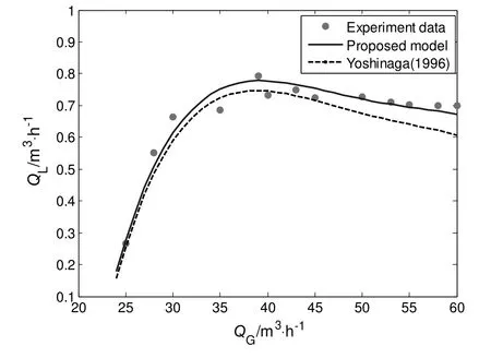
Fig.12.Comparison between the results of different models and the experimental data at γ=0.3.
Fig.13 shows the effects of pipe diameter on the performance of airlift pump.Three diameters usually used in engineering applications are set:D=30 mm,D=40 mm,D=50 mm.The corresponding performance could be predicted by the current model.It could be found that diameter has little effect on the water flow rate when QG< 40 m3·h-1and that big diameter could slightly increase the water flow rate when QG≥ 40 m3·h-1.From the momentum Eq.(2),we could know,the water flow rate is a result of competition among gravitational,frictional and inertial forces.For low flow rates of gas and water flow,the frictional force of pipe wall is not obvious.As the mixture flow rates increase,the frictional force also increases.Thus,different pipe diameter produces some differences in the output water flow rate when QG≥ 40 m3·h-1.Moreover,the big diameter produces a smaller pressure loss as shown in Eqs.(11)-(12),which is just the reason why big diameter could slightly increase the water flow rate at QG≥ 40 m3·h-1.
4.Conclusions
In this work,the flow characteristics in riser pie and suction pipe were investigated by using the high speed recorder and LDV,respectively.A modified model was presented to predict the performance of airlift pump operating in gas-liquid two-phase flow.The main results obtained are list below.
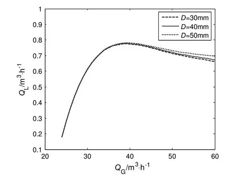
Fig.13.The effects of pipe diameters on the performance of airlift pump at γ=0.3.
(1)In airlift pump,slug flowtransitsin to an unstable flowstructure asthe air flowrate increases.The unstable flowstructure consisting of water falling film,bubbly mixture,waterascending filmis formed due to the instability of the interface between the gas and liquid phase.
(2)The proportions of water falling film,bubbly mixture,water ascending filmare very sensitive to the air flowrate.The proportion of water falling film decreases gradually and finally disappears with increasing airlfowrate.The proportion of bubbly mixture in the flow cycle firstly increases to its maximum and then decreases slightly.The proportion of water ascending film increases with increasing air flow rate.
(3)The bubbly mixture has a strongest capacity for accelerating the water phase due to the large inter-facial area and the high slip velocity.
(4)In suction pipe,the average axial velocity in a range of 0-0.45 m·s-1shows a flat profile.It increases with increasing submergence ratio.
(5)The modified model was valid to predict the performance of airlift pump operating in gas-liquid flow in a margin of±12%.
Nomenclature
Α pipe cross-sectional area,m2
C friction coefficient
CaChisholm's parameter
D pipe inner diameter,m
g gravity acceleration,m·s-2
J volumetric flow,m·s-1
L static depth of water,m
L1length of suction pipe,m
L2length of riser pipe,m
LDV Laser Doppler Velocimetry
M mass flow rate,kg·s-1
p pressure,Pa
Q flow rate,m3·h-1
T flow cycle,s
Δt duration time,s
u velocity,m·s-1
V average axial velocity,m·s-1
α proportions
γ submergence ratio
ε volumetric fraction
ξ coefficient of length loss
ρ mass density,kg·m-3
τ shear stress,N·m-2
ν kinematic viscosity,m2·s-1
Φ2Ltwo-phase multiplier
χ L-M parameter
Subscripts
E cross section of water inlet
G gas
GL gas-water mixture
I cross section of air injector
L water
O cross section of riser outlet
[1]N.Hatta,H.Fujimoto,M.Isobe,Theoretical analysis of flow characteristics of multiphase mixtures in a vertical pipe,Int.J.Multiphase Flow 24(1998)539-561.
[2]D.J.Reinemann,J.Y.Parlange,M.B.Timmons,Theory of small-diameter airlift pumps,Int.J.Multiphase Flow 16(1990)113-122.
[3]A.F.Mahrous,Airlift pump with a gradually enlarged segment in the riser tube,J.Fluids Eng.135(2013),031301.
[4]S.Z.Kassaba,H.A.Kandila,H.A.Wardaa,Experimental and analytical investigations of airlift pumps operating in three-phase flow,Chem.Eng.J.131(2007)273-281.
[5]S.Z.Kassaba,H.A.Kandila,H.A.Wardaa,et al.,Air-lift pumps characteristics under two-phase flow conditions,Int.J.Heat Fluid Flow 30(2009)88-98.
[6]W.H.Ahmed,H.M.Badr,Dual-injection airlift pumps:An enhanced performance,Part.Sci.Technol.30(2012)497-516.
[7]W.H.Ahmed,A.M.Aman,H.M.Badr,Air injection methods:The key to a better performance of airlift pumps,Exp.Thermal Fluid Sci.70(2016)354-365.
[8]T.Yoshinaga,Y.Sato,Performance of an air-lift pump for conveying coarse particles,Int.J.Multiphase Flow 22(1996)223-238.
[9]W.E.Castro,P.B.Zielinski,Pumping characteristics of small airlift pumps,J.World Aquacult.Soc.11(1-4)(1980)163-174.
[10]P.Hana fizadeh,S.Ghanbarzadeh,M.H.Saidi,Visual technique for detection of gasliquid two-phase flow regime in the airlift pump,J.Pet.Sci.Eng.75(2011)327-335.
[11]P.Hana fizadeh,A.Hojati,A.Karimi,Experimental investigation of oil-water two phase flow regime in an inclined pipe,J.Pet.Sci.Eng.136(2015)12-22.
[12]H.E.Zaraki,M.Majidniya,M.H.Abadshapoori,et al.,Experimental investigation of flow regime and efficiency of airlift pumps with tapered upriser pipe,Multiph.Sci.Technol.28(2)(2016).
[13]C.T.Moisidis,E.G.Kastrinakis,Two-phase flow pattern transitions of short airlift pumps,J.Hydraul.Res.48(2010)680-685.
[14]C.T.Moisidis,E.G.Kastrinakis,Pressure behaviour in riser tube of a short airlift pump,J.Hydraul.Res.48(1)(2010)65-73.
[15]H.Tighzert,M.Brahimi,N.Kechroud,et al.,Effect of submergence ratio on the liquid phase velocity,efficiency and void fraction in an air-lift pump,J.Pet.Sci.Eng.110(2013)155-161.
[16]A.H.Stenning,C.B.Martin,An analytical and experimental study of air-lift pump performance,J.Eng.Power 90(1968)106-110.
[17]D.Hu,Y.Kang,C.Tang,Modeling and analysis of airlift system operating in threephase flow,China,Ocean Eng.29(2015)121-132.
[18]D.Hu,C.L.Tang,S.P.Cai,et al.,The effect of air injection method on the airlift pump performance,J.Fluids Eng.134(2012)111302.
[19]A.Goharzadeh,K.Fernandes,Experimental characterization of a modi fied airlift pump,ASME 2014 International Mechanical Engineering Congress and Exposition,American Society of Mechanical Engineers,2014(V007T09A011-V007T09A011).
[20]A.Tramba,A.Topalidou,E.G.Kastrinakis,Visual study of an airlift pump operating at low submergence ratios,Can.J.Chem.Eng.73(1995)755-764.
[21]H.Kato,T.Miyazawa,S.Timaya,A study of an air-lift pump for solid particles,Bull.JSME 18(1975)286-294.
[22]D.P.Margaris,D.G.Papanikas,A generalized gas-liquid-solid three-phase flow analysis for airlift pump design,J.Fluids Eng.119(1997)995-1002.
[23]T.M.Liou,Y.Y.Wu,Y.Chang,LDV measurements of periodic fully developed main and secondary flows in a channel with rib-disturbed walls,J.Fluids Eng.115(1993)109.
[24]T.M.Liou,J.J.Hwang,Effect of ridge shapes on turbulent heat transfer and friction in a rectangular channel,Int.J.Heat Mass Transf.36(1993)931-940.
[25]T.M.Liou,D.A.Santavicca,Cycle resolved LDV measurements in a motored IC engine,J.Fluids Eng.107(1985)232-240.
[26]W.Fan,J.Chen,Y.Pan,et al.,Experimental study on the performance of an air-lift pump for artificial upwelling,Ocean Eng.59(2013)47-57.
[27]G.F.Hewitt,D.N.Roberts,Studies of Two-phase Flow Patterns by Simultaneous X-ray and flash Photography,United Kingdom Atomic Energy Authority,1969 21-59.
[28]E.M.Wahba,M.A.Gadalla,D.Abueidda,On the performance of air-lift pumps,from analytical models to large eddy simulation,J.Fluids Eng.136(2014)111301.
[29]A.Tomiyama,H.Minagawa,N.Furutani,Application of a two-phase flow model based on local relative velocity to gas-liquid-solid three-phase flows,JSME Int.J.,Ser.B:Fluids Therm.Eng.38(1995)555-562.
[30]R.W.Lockhart,R.C.Martinelli,Proposed correlation of data for isothermal twophase,two-component flow in pipes,Chem.Eng.Prog.45(1949)39-48.
[31]D.Chisholm,A theoretical basis for the Lockhart-Martinelli correlation for twophase flow,Int.J.Heat Mass Transf.10(1967)1767-1778.
[32]S.L.Smith,Void fractions in two-phase flow:a correlation based upon an equal velocity head model,Proc.Inst.Mech.Eng.184(1969)647-664.
[33]A.Tomiyama,N.Furutani,H.Minagawa,et al.,Numerical analyses of air lift pumps based on the multi- fluid model,Jpn.J.Multiphase Flow 6(2)(1992)173-188.
 Chinese Journal of Chemical Engineering2018年2期
- Chinese Journal of Chemical Engineering的其它文章
- Transport hindrances with electrodialytic recovery of citric acid from solution of strong electrolytes
- Experimental investigation on CO2-light crude oil interfacial and swelling behavior
- Biosynthesis of 4-hydroxyphenylpyruvic acid from L-tyrosine using recombinant Escherichia coli cells expressing membrane bound L-amino acid deaminase☆
- Process development for producing a food-grade glucose solution from rice straws
- Carbon dioxide induced degradation of diethanolamine during absorption and desorption processes
- Biodegradation of natural and synthetic estrogens in moving bed bioreactor
