Effect of Plaque Composition on Biomechanical Performance of a Carotid Stent: Computational Study
Xinyang Cui, Qingshuai Ren, , Zihao Li, Kun Peng, Gaoyang Li, , Zhaoyong Gu and Aike Qiao,
Abstract: Clinical application of bare metal stents is constrained by the occurrence of instent restenosis, mainly due to the complex biomechanical environment in the body.Numerical simulation method was used to evaluate the effect of plaque composition on stent performance in a carotid artery. CT angiography (CTA) data were used as a reference, and zero-load state of the carotid artery was used to establish a 3D stenotic artery model. Different plaque compositions, calcified and hypo-cellular were defined in Model 1 and Model 2, respectively. Interactions between the stents and arterial tissues within the stent crimping-expansion process were analyzed to explore the effects of plaque composition on the mechanical parameters of carotid stents. Goodman diagram and fatigue safety factor (FSF) were analyzed to explore the effects of plaque composition on fatigue performance of a carotid stent in the stent service process. In the stent crimping-expansion process, the von Mises stress in the stent and the dog-boning ratio in Model 1 were higher than that in Model 2. The calcified plaque prevented the stent from expanding the stenotic vessel to a pre-set diameter. Thus, the risk of rupture in the calcified plaque was higher than that in the hypo-cellular plaque. Plaque also affected the stress/strain in the vessel wall, which was observed to be lower in Model 1 than in Model 2. This indicated that calcified plaque could decrease the stress-induced injury of arterial tissues. Within the stent service process, the stents used in these two models were predicted to not fail under fatigue rupture as calculated by the Goodman diagram.Additionally, the points closer to the fatigue limit were generally observed at the inner bend of the stent crowns. The FSF of the stent in Model 1 was lower than that in Model 2.The stent operating in the presence of calcified plaques suffered high risk of fractures.Reliability and fatigue performance of the stent were found to be associated with plaque composition. Hence, this study may provide stent designers an approach toward enhancing the mechanical reliability of a stent.
Keywords: Plaque composition, biomechanical, carotid stent.
1 Introduction
Carotid atherosclerotic disease is a significant source of mortality accounting for approximately 30% of all ischemic strokes [Yuan, Teng, Feng et al. (2015)]. Stent intervention has been widely used in the clinical treatment of atherosclerotic diseases.However, the clinical success of bare metal stents is constrained by resultant in-stent restenosis. Experimental and in vivo studies demonstrate that a complex biomechanical environment can lead to stent failure and fracture (SF) [Morlacchi, Pennati, Petrini et al.(2014); Auricchio, Constantinescu, Conti et al. (2015)], eventually causing an in-stent restenosis [Shaikh, Maddikunta, Djelmami-Hani et al. (2008); Adlakha, Sheikh, Wu et al.(2010)]. A complex biomechanical environment is induced by the unique arterial geometry, plaque composition, loading, and boundary conditions [Holzapfel, Mulvihill,Cunnane et al. (2014)].
For conducting finite element studies, it is important to obtain accurate information regarding patient-specific arterial geometry in vivo [Holzapfel, Mulvihill, Cunnane et al.(2014)]. Dordoni et al. [Dordoni, Meoli, Wu, et al. (2014)] pointed out that plaque geometry played an important role in the mechanical performance and fatigue behavior of a stent. In our previous research, we used a realistic geometry model to calculate the mechanical parameters and fatigue performance of a stent [Cui, Ren, Li et al. (2018)].Khosravi et al. [Khosravi, Bahreinizad, Bani et al. (2017)] simulated three types of hyperplastic plaques and revealed critical effects of material parameters on stent deformation. The research conducted by Pericevic et al. [Pericevic, Lally, Toner et al.(2009)] indicated the significant influence of plaque composition on stress-induced injury within the artery during stent intervention. Most studies on stent implantation have treated the vessel wall and the plaque as a single object [Gijsen, Migliavacca, Schievano et al. (2008); Ragkousis, Curzen and Bressloff (2014)], due to which the effect of different plaque compositions on the mechanical properties of a stent have been largely ignored. Therefore, it is necessary to conduct a comprehensive study on the interaction between the stent and the arterial tissue, wherein the effect of plaque compositions on the mechanical parameters of a carotid stent will have high priority.
The local damage of structure will lead to SF, which can be predicted by the structural mechanical parameters [Xu, Ding, Lu et al. (2016)]. From the perspective of loading and boundary conditions, SF can result from the coupling of two stress states: A large deformation during stent implantation and a micro-deformation during the stent service period caused by the pulsating force in the artery [Morlacchi, Pennati, Petrini et al.(2014); Auricchio, Constantinescu, Conti et al. (2015)]. Many researchers established a 3D patient-specific model to simulate stent implantation. However, neither the cyclic loading conditions [Auricchio, Conti, Beule et al. (2011)] nor the effect of plaque presence on the mechanical properties of a stent was taken into account [Early and Kelly(2009); Zhao, Gu and Froemming (2012) ]. The role of vaszcular calcification in inducing SF was analyzed by Halwani [Halwani, Anderson, Brott et al. (2012)]. Morlacchi et al.[Morlacchi, Pennati, Petrini et al. (2014)] demonstrated that the increased risk of stent fracture was associated with the presence of localized plaque calcification. Furthermore,cyclic loading may cause stent fatigue and fracture. However, these studies used highly idealized arterial geometries and investigated only one type of calcific lesion. From the mechanical viewpoint, it is necessary to analyze the effect of the atherosclerotic plaque compositions on the mechanical and fatigue performance of a carotid stent based on a realistic arterial geometry.
In this paper, we used a numerical simulation tool ABAQUS/Standard 6.13, to analyze the mechanical reliability and fatigue behavior of a carotid stent. Two typical plaque properties were selected to reveal the effects of plaque composition on the biomechanical performance of a carotid stent. This study will help stent designers in increasing the mechanical reliability of stents in order to treat various lesions.
2 Methods
Two models were developed to represent plaques with different material compositions,i.e. calcified (defined as Model 1) and hypo-cellular (defined as Model 2), respectively.Subsequently the stent-plaque-vessel wall interactions during stent implantation and stent service period were simulated.
2.1 Patient-specific model reconstruction and parameterized stent design
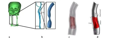
The CT angiography (CTA) images of a stenotic carotid bifurcation of a 56 years old male were processed with Mimics 15.0. A patient-specific 3D artery model was reconstructed using the software “Freeform Plus 2013” (Fig. 1). Firstly, CTA (Fig. 1a)images were collected at end-diastole (80 mmHg) and the lumen of carotid artery (CA)main branches (original fluid model) were established. Following this, the lumen of internal carotid artery (ICA) branch was selected (Fig. 1b). Realistic plaque geometry was generated by a logical subtraction between the healthy 3D lumen and the stenotic lumen (as shown in Fig. 1c); the plaque is illustrated with a red marker in stenotic artery segment. The healthy 3D lumen of the ICA branch was obtained by repairing the stenotic lumen using the software “Freeform Modeling Plus” and the thickness of the ICA was assumed to be 30% of the non-diseased luminal radius [Auricchio, Conti, Beule et al.(2011)]. As shown in Fig. 1c, a stenotic arterial geometric model at 80 mmHg was established. The next step involved the acquisition of the ICA geometry at zero-load state,which could then be used as the starting geometry of the model. An artery with no pulsating pressure is defined to be at the zero-load state. Based on the references report by Tang's research group, a circumferential shrinkage data (7.9%) was used to shrink the in vivo plaque geometry [Huang, Yang, Yuan et al. (2009); Fan, Yao and Tang (2016)] in order to obtain the computational zero-load geometry (Fig. 1d). The ICA diameter-based stenosis ratio was 57.5%.

Figure 1: Patient-specific CA Model: (a) 3D reconstruction of cerebral vascular tree from CT images; (b) Stenotic lumen of ICA branch (CCA: common carotid artery; ICA:Internal carotid artery; ECA: external carotid artery); (c) The ICA geometric model at 80 mmHg. (d) Calculated Geometric Model of ICA at zero-load state
The effect of personalized geometry of a stenotic artery on the mechanical performance of a stent was evaluated in our previous research [Cui, Ren, Li et al. (2018)]. The stent structure used in this paper is identical to that used in a previous study. As shown in Fig.2, the stent was formed by six unit cells and each single cell consisted of 12 crowns.

Figure 2: Geometrical dimensions of the stent
The software Hypermesh11.0 was used to mesh the combination of the stent and the stenotic artery. The vessel wall and the corresponding plaque model were meshed with the tetrahedral element, which was finer and would thereby avoid a disturbance of irregular structures in the stenotic artery model. The Ogden model was used to define the calcified and hypo-cellular plaques material properties (Eq. (1)). Detailed information was listed in Tab. 1.


Table 1: Details of the combination of the stent and the stenotic artery
2.2 Boundary conditions and loading steps
After positioning the stent inside the CA, a surface-surface contact of sliding friction(friction factor of 0.2) was applied between the external surface of the stent and the internal surface of the plaque and vessel wall [Yang, Zhang and Marder (2008)]. In order to ensure the transfer of force and displacement between the plaque and the vessel wall without relative slippage, the external surface of the plaque and the inner surfaces of the vessel were assumed to be bonded. To avoid any rotation inside the vessel, the nodes belonging to the stent surface were constrained in the tangential direction. The artery was constrained in the section near the plaque to prevent any displacements and rotations.
Three simulation steps were executed:
Step 1: Reproduction of a stress/strain field in the arterial tissue before stenting. A blood pressure of 80 mmHg was applied to the inner surface of the vessel wall in order to recover the in vivo plaque morphology together with proper initial stress/strain conditions[Huang, Yang, Yuan et al. (2009)].
Step 2: Stent crimping-expansion. In order to simulate crimping of the stent on a balloon catheter, a displacement load corresponding to a diameter of 15% was set. Subsequently,the stent was delivered to the stenotic lesion. A uniform radial deformation was imposed on the inner surface of the carotid stent along the longitudinal axis, up to a diameter of 1.1 times of the healthy vessel inner diameter [Dordoni, Meoli, Wu et al. (2014)]. At the end of this step, the stent was deflated and the plaque and the vessel wall were elastically recoiled.Step 3: Diastolic-systolic cyclic loading (service process). In Ohsaki et al.'s research[Ohsaki, Miyamura, Zhang et al. (2016)], a simple constitutive model for cyclic loading was proposed for steel materials. In this research, after subjecting the stent to a large deformation in the expansion stage, the stent underwent pulsatile loading produced from the oscillation of the internal blood pressure. Take Whelton's research as a reference[Whelton and Carey (2017)], a pulsatile blood pressure, oscillating between 80 mmHg(diastole) and 130 mmHg (systole) was applied to the inner surfaces of the vessel wall.Stabilization in the constitutive model response after three pulsatile loading cycles has already been reported [Marrey, Burgermeister, Grishaber et al. (2006)]. In the current study, the pulsatile loading was simulated for three cardiac cycles.
3 Results and discussion
3.1 The von Mises stress/strain distribution analysis (in the stent crimping-expansion process)
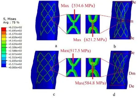
During stent expansion phase in the “stent crimping-expansion” process, the artery underwent a simultaneous radial expansion and axially shrinkage. As shown in Fig. 3a and Fig. 3c, circumferential bulges occurred in the stenotic artery. Upon removal of the radial load, the vessel and plaque recoiled radially, thereby exerting a force on the stent resulting in its radial shrinkage. As observed in Fig. 3b and Fig. 3d, both plaques featured two wide distal ends (De) and a narrow central part (Dm) and the strongest contraction of the plaque was located at the narrowest position of the artery. The phenomenon where the distal end of the stent expanded more than its central portion was called “dog-boning”effect and was a result of non-uniform stent expansion. The dog-boning ratio calculated using Eq. (2) was 47.4% in Model 1 and 39.9% in Model 2. A higher dog-boing ratio correlated with a greater difference in the circumferential stress in the stent [Khosravi(2017)]. The non-uniform expansion of the stent was more obvious in Model 1, and the stress in the distal and central zones of the stent showed marked differences. Thus, it is necessary to identify the effect of plaque composition on “dog-boning” effect.

As seen in Fig. 3, upon complete expansion of the stent, the maximum von Mises stress concentrated at the crown bend within the stent, which was located near the narrowest part of the arterial tissue. The minimum von Mises stress region was located in the supporting link within the stent, which was far away from the narrowest position in the tissue. The stresses within the stents decreased after the stent recoiled; however, the high von Mises stress region was still located at the same station. The highest von Mises stresses in the stents were 621.2 MPa and 584.8 MPa in Model 1 and Model 2,respectively. They were thus, higher than the yield strength of the stent material but lower than ultimate tensile stress (692 MPa). This indicated that the stent would not fail because of a fracture in the stent crimping-expansion process.

Figure 3: Contours of the von Mises stress in the combination of the stent and the stenotic artery when the stent expanded completely (a&c) and recoiled elastically (b&d).(Upper: Model 1, Lower: Model 2, the arrow marks the location of the maximum value within the stent)
When the stent recoiled, the artery recoiled elastically as well. The minimum diameter of the artery in Model 1 reached 2.47 mm, whereas the diameter-based stenotic ratio decreased from 57.5% to 38.25%. However, in Model 2, the minimum arterial diameter reached 2.84 mm and the diameter-based stenotic ratio reached 29%. The von Mises stress in the stent and diameter-based stenotic ratio were both higher in Model 1 than in Model 2. The stent expansion may not reach an optimal state owing to the high resistance offered by the calcified plaque. This indicates that the mechanical performance of the stent should be enhanced when used to treat the lesion with the calcified plaque.
Heavily calcified arterial diseases remain a big challenge for percutaneous interventions[Chiang, Yi, Tsao et al. (2013)]. The removal of obviously calcified plaque when treating the lesion and lower plaque burden is advised not only to retain the stent functionality but also as a necessity to decrease the occurrence of in-stent restenosis. The applicable methods include a directional atherectomy and rotational atherectomy, both of which can rupture the plaque. Additionally, the cutting-balloon method is particularly useful for completely rupture the plaque [Mahdi, Pathan, Harrell et al. (1998); Sharma, Kini,Mehran et al. (2004); Lu, Duan and Qiao (2015)].

Figure 4: Contours of the von Mises stress/strain within the plaque after the stent elastic recoiled (Upper: Von Mises stress, Lower: Strain; a&c: Model 1, b&d: Model 2. The arrow marks the location of the maximum value)
A plaque is predicted to rupture when the fracture stresses and strains reach 366.6±220.5 kPa and 0.499±0.088, respectively [Lawlor, O'Donnell, O'Connell et al. (2011)]. In this paper, the maximum stresses within the plaque for both models were far higher than the stress thresholds value for plaque to rupture (as shown in Figs. 4(a) and 4(c)). It indicated that the stent could rupture the plaque simultaneously by providing sufficient radial support force, which is similar to the function of cutting balloon. To ensure safety and efficacy, filtration devices were required in the stent implantation process.
The relative error ratio of stress between Model 1 and Model 2 was |1.249-1.072|/1.249=14.17%. This indicated that the calcified plaque had a stronger inclination to rupture than the hypo-cellular plaque when the artery expanded to a pre-set healthy diameter. However, a higher strain was found in the plaque in Model 2. The relative error ratio of the plaque strain between the two models was close to 30% (|0.443-0.311|/0.443=29.8%). This could be attributed to the different plaque material properties that might have influenced the mechanical properties of the stent.
The stresses/strains in the vessel walls in the two different models were also compared.After the stent recoiled, the maximum stresses in the vessel wall in Model 1 and Model 2 were 0.1898 MPa and 0.2596 MPa, respectively. The maximum strains of the vessel wall in Model 1 and Model 2 were 0.1039 and 0.1451, respectively. It indicated that the calcified plaque had a protective effect on the vessel wall when the artery expanded to a pre-set healthy diameter. The calcified plaque reduced the stress injury of the artery in the stent crimping-expansion process, which was beneficial to the recovery of the vascular endothelium [Pericevic, Lally, Toner et al. (2009)].
3.2 Fatigue performance analysis (in the stent service process)
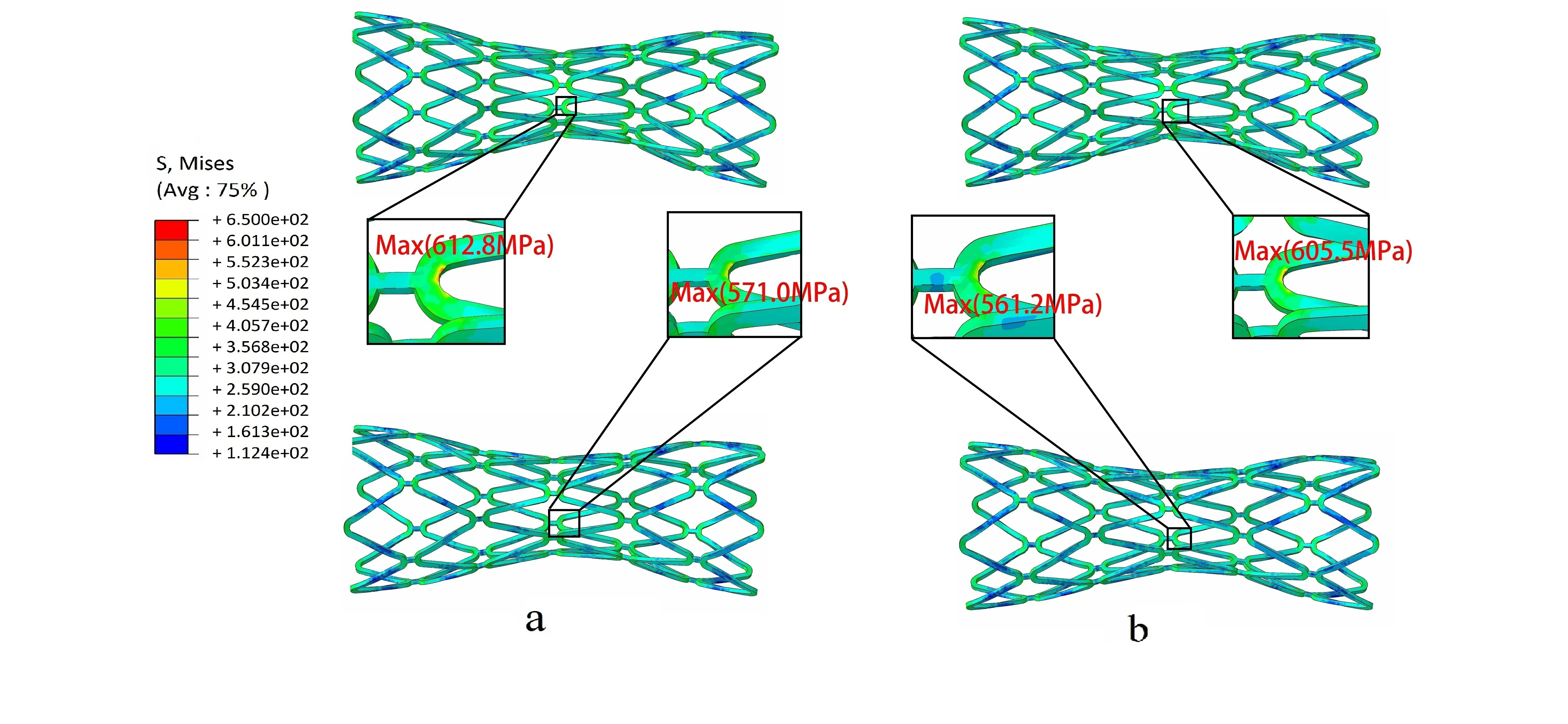
The evaluation of fatigue performance was based on numerical results. As shown in Fig. 5a,when the diastolic pressure was 80 mmHg, the maximum von Mises stresses on stent were 612.8 MPa in Model 1 and 571.0 MPa in Model 2. When the systolic pressure was 130 mmHg, the maximum von Mises stresses were 605.5 MPa in Model 1 and 561.2 MPa in Model 2 (Fig. 5b). Thus, it was evident that the maximum von Mises stresses were located near the inner bend of the crowns while the minimum von Mises stress was located at the Ilink bar, which was similar to the finding in the stent crimping-expansion process.

Figure 5: Contours of von Mises stress in the stent under different pulsatile pressure.Upper: Model 1, Lower: Model 2, (a) Diastole (80 mmHg), (b) Systole (130 mmHg)
According to the Food and Drug Administration (FDA) guidelines, stents must survive 10 years of equivalent life fatigue testing or approximately 4×10⁸loading cycles under simulated physiological loading [Karanasiou, Papafaklis, Conway et al. (2017)].Goodman diagram analysis was recommended by the FDA to evaluate the fatigue resistance of a stent to physiological pulsatile loading.
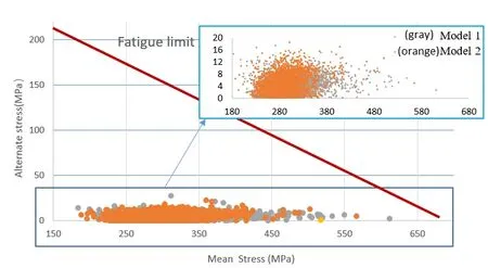
As indicated in Fig. 6, all points fall below the fatigue limit curve of the stent material.This indicted that the stent, serviced in the two models would not fail due to fatigue fracture in ten years. Further, the stent investigated in this paper was able to pass the fatigue life of 4×10⁸cycles under pulsatile loading. The closer the fatigue limit, the more dangerous the structure will be. Here the distribution of the gray and orange points was similar, and a few gray points were closer to the fatigue limit line than the orange points.This indicted that the stent serviced in Model 1 had a higher fracture risk than in Model 2.Thus, special attention should be paid to the mechanical ability of the stent in the lesion with the calcified plaque.

Figure 6: Goodman diagrams analysis in Model 1 (gray) and in Model 2 (orange). The endurance limit for zero mean stress of the 316L SS material was assumed 207 MPa(ordinate value) while the ultimate stress was equal to 692 MPa (abscissa value)

where σ1m,σ2mand σ3mdenote the principal mean stresses respectively [Hsiao, Wu,Yin et al. (2014)].
The safety of the stent was quantitatively demonstrated using Eq. (4). FSF value greater than 1.0 indicates resistance of stent to fatigue failure.

where σuandrepresent the ultimate stress and the endurance limit for zero mean stress of the 316L SS stent material, respectively [Marrey, Burgermeister, Grishaber et al.(2006); Li, Luo, Xie et al. (2010) ].
Twenty dangerous nodes in the stent were selected (Fig. 7) and FSF value were predicted.The FSF of the most dangerous point was 1.09 (>1) in Model 1. The stent FSF in two different models surmounted 1, theoretically indicating that the stent would not suffer from fatigue failure. The FSF in Model 1 was smaller than in Model 2 (Fig. 8), suggesting that reliability of the stent predicted using a calcified plaque model was less than that predicted using the hypo-cellular plaque model. Stent servicing in an environment with calcified plaques displayed a higher risk of fracture than in environments with hypo-cellular plaques. Results from fatigue performance in the stent service process re-confirmed the mechanical analysis in the stent crimping-expansion process.

Figure 7: Twenty different nodes in the high von Mises stress area
4 Conclusions
This study analyzed the effects of plaque composition on the biomechanical performance of carotid stents. Different plaque compositions (i.e. calcified and hypo-cellular) were assigned to the plaque material. Plaque compositions affected non-uniform expansion of the stent. Higher von Mises stress in the stent and larger dog-boning ratio were observed in the calcified model. These results suggested that the stent support performance should be enhanced when treating lesions with calcified plaques. When the artery expanded to a pre-set healthy diameter, the calcified plaque showed a higher inclination to rupture compared to the hypo-cellular plaque. However, the calcified plaque exerted a protective effect on the vessel wall.
The maximum von Mises stress at all stages was always located at the inner bend of the crowns. The FSF of the stent in the calcified model was lower than that in the hypocellular model. Thus, the stent, operating in an environment with calcified plaques showed a higher risk of fracture. Thus, SF risk were associated with plaque composition owing to which the composition and material properties of atherosclerotic plaques must be considered in order to fully assess the accurate mechanical performance of a stent.
A limitation of the study from a modeling perspective was that the plaque constituents were sophisticated and diverse in nature, for example, fibrous, lipoid, calcified, inflamed,etc. [He, Wang, Huang et al. (2016)]. Here, more pragmatic plaque models need to be established in order to discuss adaptation of the stents. This study followed a generalist approach and was not limited to 316L stainless steel. Thus, future studies should be focused on other metallic materials.
This study can help support interventional planning for different lesions in order to minimize the risk of stent fatigue and fracture. Additionally, this study can provide a valuable reference for increasing the mechanical reliability of carotid stents.
Acknowledgment:This study was supported by Major Project of Science and Technology of Beijing Municipal Education Commission and Type B Project of Beijing Natural Science Foundation (KZ201710005007).
 Computer Modeling In Engineering&Sciences2018年9期
- Computer Modeling In Engineering&Sciences的其它文章
- Improved State-Based Peridynamic Lattice Model Including Elasticity, Plasticity and Damage
- Eddy Current Analyses by Domain Decomposition Method Using Double-Double Precision
- Machining Parameters Optimization of Multi-Pass Face Milling Using a Chaotic Imperialist Competitive Algorithm with an Efficient Constraint-Handling Mechanism
- UPFC Based Real-Time Optimization of Power Systems for Dynamic Voltage Regulation
- Spline Fictitious Boundary Element Alternating Method for Edge Crack Problems with Mixed Boundary Conditions
- A Computer-Aided Tuning Method for Microwave Filters by Combing T-S Fuzzy Neural Networks and Improved Space Mapping
