Spline Fictitious Boundary Element Alternating Method for Edge Crack Problems with Mixed Boundary Conditions
Z. Xu, M. Chen and X. M. Fan,
Abstract: The alternating method based on the fundamental solutions of the infinite domain containing a crack, namely Muskhelishvili's solutions, divides the complex structure with a crack into a simple model without crack which can be solved by traditional numerical methods and an infinite domain with a crack which can be solved by Muskhelishvili's solutions. However, this alternating method cannot be directly applied to the edge crack problems since partial crack surface of Muskhelishvili's solutions is located outside the computational domain. In this paper, an improved alternating method, the spline fictitious boundary element alternating method (SFBEAM),based on infinite domain with the combination of spline fictitious boundary element method (SFBEM) and Muskhelishvili's solutions is proposed to solve the edge crack problems. Since the SFBEM and Muskhelishvili's solutions are obtained in the framework of infinite domain, no special treatment is needed for solving the problem of edge cracks. Different mixed boundary conditions edge crack problems with varies of computational parameters are given to certify the high precision, efficiency and applicability of the proposed method compared with other alternating methods and extend finite element method.
Keywords: Spline fictitious boundary element alternating method, mixed boundary conditions, edge crack problem, Muskhelishvili's solutions, stress intensity factor.
1 Introduction
Cracks exist in structures becauseof manufacture, usage, or the defects of material.Therefore, fracture mechanics plays an important role in engineering practice, such as aeronautics, astronautics and machinery manufacturing. Stress intensity factor is the most critical problem in fracture mechanics, but only a few cases can get the closed-form solution of stress intensity factor (SIF). So, numerical methods are the most common methods for solving crack problems. The finite element method (FEM) is widely used because of its strong adaptability, but more elements are set up at the crack tips due to the severe stress gradient, reducing the accuracy and efficiency of the method greatly. In order to solve the fracture problems efficiently, an improved finite element method,extended finite element method (XFEM) [Pathak, Singh and Singh (2013)], is proposed.The extended finite element method does not need to mesh the geometric or physical interfaces inside the structure, so it can overcome the difficulties caused by the highdensity mesh generation at the crack tip. However, the shape function used by XFEM makes it easy to approach the linear correlation, which greatly increases the difficulty of the algebraic equation convergence. The boundary element method (BEM) [Wünsche,García-Sánchez, Sáez et al. (2010)] is also used commonly in the analysis of fracture mechanics as only the boundary needs to be discretized. However, it needs to add more elements close to the crack tips, which make it time-consuming.
Compared with the above numerical methods which are conducted to solve one crack problem, the alternating method is proposed to solve crack problems effectively using the combination of two different simple problems. The principle of the alternating method is to decompose a finite problem with a crack into the problem without crack and the infinite problem with a crack, and after that those two different problems are solved, respectively.Without the crack tip processing, this method can greatly improve the solving efficiency.Applications of the alternating method in the fracture mechanics involves the multi-crack problem [Chen (2011); Chen and Wang (2012); Chen and Wang (2014); Chen (2014)],surface elliptical cracks in 3-D bodies [Shah and Kobayashi (1973); Thresher and Smith(1972)] and surface crack of pump shaft [Chen, Kuo and Shvarts (1993)].
The infinite problem with a crack can be solved by using boundary integral equation or the fundamental solutions with a crack (Muskhelishvili's solutions). Compared with the Muskhelishvili's solutions which are derived from the mathematical method, it is lower accurate to solve the infinite problem with a crack by the boundary integral equation which bring more numerical errors. On the other hand, the problem without the crack can be conducted by using the FEM or direct BEM. The finite element alternating method(FEAM) is widely used due to its good applicability, including prediction of fatigue crack growth life of 3D model [Wang, Haynes, Huang et al. (2015); Nikishkov, Park and Atluri(2001); Tian, Dong, Bhavanam et al. (2014); Tian, Dong, Phan et al. (2015)], surface crack analysis of cylinder [Kamaya and Nishioka (2005)], simulation of surface crack and full thickness crack propagation [Park and Nikishkov (2011)] and crack simulation and analysis of countersunk rivets [Shi and Li (2006)]. In addition, the direct BEM is applied to solve the problem without crack. The BEM is attractive since only the boundaries of the problem for this method need to be modeled and hence, modeling effort is considerably reduced. Rajiyah et al. [Rajiyah and Atluri (1988)] use the direct boundary element alternating method (BEAM) to solve the SIF and the weight function of the 2D mixed crack problem. Raju et al. [Raju and Krishnamurthy (1992)] carried out detailed calculation steps of the method and calculated the SIF of the 2D mixed crack problem. Ting et al. [Ting, Chang and Yang (1995); Ting, Chen and Yang (1999); Chen,Ting and Yang (2000)] apply this method to the analysis of the third kinds of multi crack problems and the analysis of two-dimensional plate with holes.
In the edge crack problem, since the crack face tractions in Muskhelishvili's solutions are defined on the entire embedded plane with the whole crack with two crack tips, it is necessary to define tractions over the entire plane, including the fictitious tractions on the crack face defined outside the finite domain, as shown in Fig. 1. However, the FEM and the direct BEM, which are based on the finite domain, cannot calculate the fictitious tractions on the crack outside the finite domain, so the FEAM and the BEAM cannot be directly applied in edge crack problem. In order to overcome this difficulty, Rajiyah et al.[Rajiyah and Atluri (1988)] assumed that there is a mirror image between the outside fictitious tractions and the inside tractions, as shown in Fig. 1(a), namely mirroring method. Besides, constant tractions or linear tractions are arranged on the fictitious crack by Raju et al. [Raju and Krishnamurthy (1992)], as shown in Fig. 1(b), namely uniform stresses method. However, the selection of tractions is arbitrary, which will affect the convergence of the equations related to the accuracy of the results.
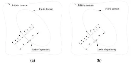
Figure 1: Treatment of edge crack
For solving the edge crack problems efficiently by the alternating method, an improved alternating method, the spline fictitious boundary element alternating method (SFBEAM)[Chen, Xu and Fan (2018)], based on an indirect BEM, spline fictitious boundary element method (SFBEM) [Su, Qin and Fan (2016); Xu, Su and Guan (2018)], and Muskhelishvili's solutions is applied in this research. Firstly, a computational model for an edge crack problem based on an infinite domain is given and then divided into two infinite domain problems by alternating method including one without a crack and another with a crack. Then, the SFBEM is used to solve the first problem and Muskhelishvili's solutions are introduced to conduct the other problem. Because the SFBEM and Muskhelishvili's solutions are formulated in the infinite domain, no special treatments are needed for solving the problem of edge crack. In the process of numerical solution, considering the distribution characteristic of the load on the crack surface, the locally thickened technique is adopted to speed up the efficiency. Finally, the SFBEAM is applied to the edge crack problem with mixed boundary conditions. Compared with other alternating methods, SFBEAM shows the high precision. Compared with the XFEM, small computational amount is needed in SFBEAM. In addition, the application of mixed boundary conditions examples show the applicability of SFBEAM.
2 SFBEAM for solving edge crack problems
2.1 Computational model of the edge crack problem based on infinite domain
A finite edge crack domain Ω is shown in Fig. 2(a). The elastic modulus, Poisson's ratio and thickness for Ω are E, υ and h, respectively. Assume the boundary of the finite domain (not including the crack surface) to be L0. The crack surface is denoted as Lc0,which has a known stress boundary conditions T0. The body forces are taken as Fl(l=1, 2).

Figure 2: Superposition principle of alternating method
The governing differential equations of the plane problem represented using the displacement functions is as follows

where F1(x, y) and F2(x, y) are body force functions, u(x, y) and v(x, y) are displacements.The boundary conditions of this model including the stress boundary conditions on crack surface, the displacement boundary conditions and the stress boundary conditions in Ω are shown as below
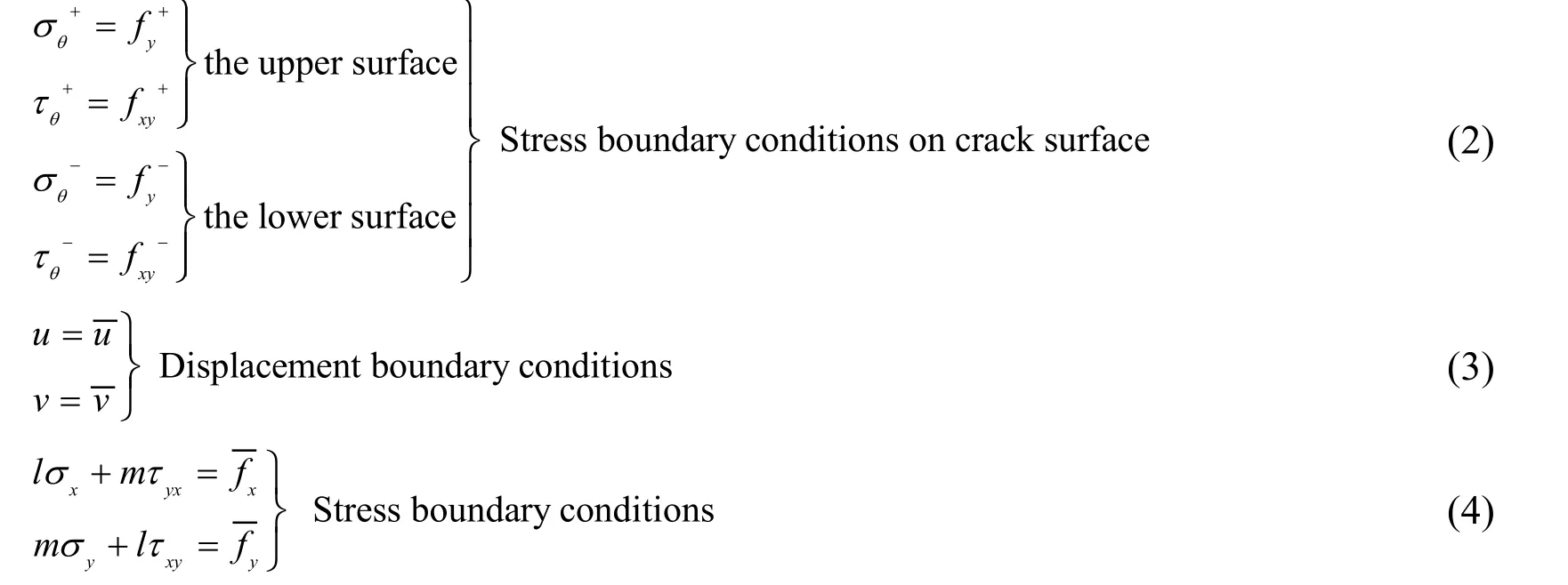
Embedding the original problem into an infinite domain in which material properties and thickness are the same, as shown in Fig. 2(b), denoting as P0,in which the fictitious crack surface lies outside the domain Ω. The boundary conditions and constitutive relations of Ω are the same as the original problem. According to the uniqueness theorem of the solution, the two problems in Fig. 2(a) and Fig. 2(b) have the same answer. P0can be decomposed into two problems including a problem embedded in an infinite non-cracked domain and an infinite cracked domain, as shown in Fig. 2(c) and Fig. 2(d), denoting as P1and P2, respectively [Wang, Haynes, Huang et al. (2015)]. It is noted that these three problems are all in the infinite domain, therefore the principle of superposition can be strictly satisfied.
The boundary conditions in Ω of P1is L1, The stress response at the crack location Lc1is T1. In the infinite domain of P2, the stress boundary condition at crack surface Lc2is T2,and the response at the boundary location is L2. Their governing differential equations are as follows
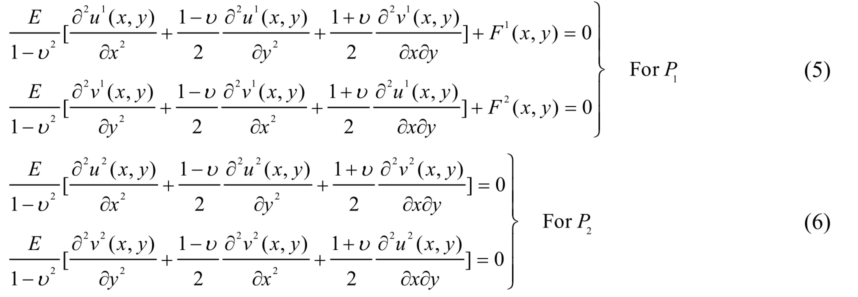
where u1(x, y)and v1(x, y) are displacements of problem P1, u2(x, y) and v2(x, y) are displacements of problem P2.
The stress and displacement functions of problems P0, P1and P2satisfy the following relationships [Chen (2011)]


2.2 SFBEM for solving infinite problem without crack
The problem P1is analyzed using the SFBEM. The SFBEM is a modified method for conventional indirect BEM. In SFBEM, nonsingular integral equations are first derived based on the fictitious boundary technique. Then spline functions are adopted as the trial functions for the unknown fictitious loads, and the boundary-segment-least-square technique is employed for eliminating the boundary residues. Because of these modifications, SFBEM is of high accuracy and efficiency in general. Assume that there is a fictitious boundary S outside Ω, and unknown fictitious loads Xl(l=1, 2) is applied along S, as shown in Fig. 3. The distance between the real boundary and fictitious boundary is d. Then, under the action of the fictitious loads Xl, the components of displacement and internal force at any point P0in the infinite domain corresponding to Ω are as follows [Su, Qin and Fan (2016)]:

Figure 3: Finite domain and fictitious boundary
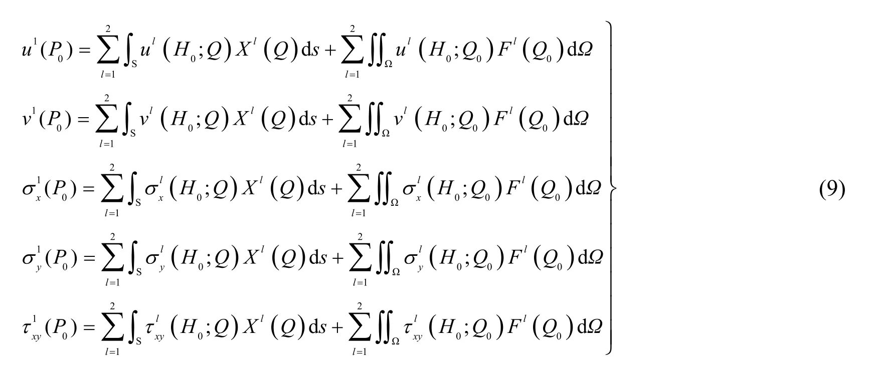
Substituting Eq. (9) into the boundary conditions along L1, one has

where H∈L1; k=1, 2 represents the two boundary conditions along boundary L for plane problems; and Lkis the known boundary conditions along L1, and Gklare the Kelvin's solutions. Note that the singular and hyper-singular integrals can be avoided in numerical solution because, in SFBEM, the source points and field points are not coincided.Because closed-form solutions to Eq. (10) are not available, the integral equations should be solved using a numerical basis. Divide the fictitious boundary S into M divisions as Sm(m=1, 2, …, M). Then a set of B-spline functions are used to express the unknown fictitious Xml(s) as follow:

where s is the local coordinate along Sm, and Nmis the number of sub-divisions within Sm.are the unknown spline node parameters and φn(s) are the third-order B-spline functions .
Substituting Eq. (11) into Eq. (10), one has the residual functions Rk(H) along boundary L1as follows

For eliminating boundary residues Rk(H), boundary L1is divided into NLsegments. Then let the integration of the residues along each segment equal zero, namely,

where ΔLdis the dth segment on boundary L1.
Substitute Eq. (13) into Eq. (12), one yields

where {X} is the column matrix consisting of the unknown spline node parameters of the fictitious loads along S; and [A] is the influence matrix of {X} corresponding to the boundary L1; and {F} and {L1} are the known column matrices depending on the body forces within Ω and the boundary conditions along L1, respectively.
After determining the spline node parameters {X}, the response of stress at the crack location {T1} can be solved as follows
Be quick, Little Two-eyes, cried the two sisters, creep under this, so that you shall not disgrace us, and they put over poor Little Two-eyes as quickly as possible an empty cask, which was standing close to the tree, and they pushed the golden apples which she had broken off under with her

where [K] is the influence matrix of {X} related to the crack location.is the known body force column matrices. Since Eq. (9) is the solution to any points for the infinite domain, the response stress {T1} includes the stress response at the actual crack location and the stress response at the fictitious crack location.
2.3 Muskhelishvili's solutions for solving infinite cracked domain
The problem P2is analyzed by using Muskhelishvili's solutions. Assume an infinite cracked domain with the crack[Wang and Atluri (1996)] subjected to the concentrated loadsandat point Q+=d+i0+at the upper crack surface and fy-andat point Q-=d+i0-at the lower crack surface as shown in Fig. 4.
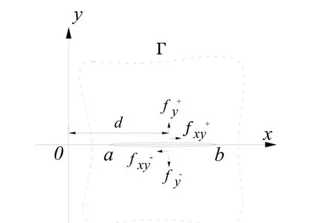
Figure 4: Crack of arbitrary length in an infinite domain
The Muskhelishvili's solutions are used to remove the crack-face cohesive stress obtained from the SFBEM solution for the alternating method. Therefore, according to Newton's third law of traction reciprocity, the concentrated load fyand fxyare the same for the upper crack surface and the lower crack surface, i.e.With this assumption, the stresses σx, σyand τxyand displacement u and v at any point, z=x+iy, can be expressed using complex functions.

where the stresses, displacement functions and SIF are expressed as follows
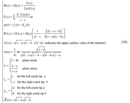
The response at the boundary location in problem P2can be determined by using Muskhelishvili's solutions as follows

Discretizing the integral equations Eq. (20). Non-uniform partition is used as the stress change is much more severe close to the crack tip, as shown in Fig. 5.
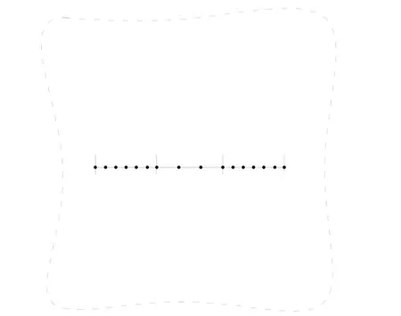
Figure 5: Non-uniform partition of crack
Let the crack Lc2be divided into I divisions, denoted as Lc2,i, then

Written in the form of matrix:

2.4 Solution of SIF by SFBEAM
An equation set consisting of Eqs. (8), (14), (15) and (22) is established. Solving this equation set, one yields

The unknown spline node parameters column matrix X can be solved from Eq. (23). Then the crack surface loading {T2} can be obtained. After that, the SIF can be solved directly using Muskhelishvili's solutions. Non-dimensional SIF can be solved as follow

where σ is are the uniform tensile stresses at far filed, a0is the crack length.
It should be noted that the crack must be at x-axis when solving the infinite problem with a crack by using Muskhelishvili's solutions. If the global coordinate is not the same as the local coordinate system, the coordinate transformations are required. In this study, the origin of the local coordinate system O′, whose coordinate in the global coordinate system is (x0, y0), is established at the intersection point of crack and finite domain, as shown in Fig. 6, and the included angle between the x-axis of the local coordinate system and the global coordinate system is θ (the positive rotation is counter-clockwise).
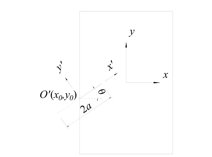
Figure 6: Transformation of overall-local coordinate
After the stress σx、σyand τxyof the uncracked body under global coordinate system are obtained from Eq. (15), a stress transformation needs to be done to change the global stress into local stress σ′x, σ′yand τ′xy, as shown below.

where [λ] is a transposed matrix as follow

The stresses and displacements on all the boundaries of Ω are obtained from Eq. (22).Sinceis established under the local coordinate system, so the global coordinate of L2must be transformed into local coordinate as follow

where (x, y) is the global coordinate and (x′, y′) is the local coordinate. After Eq. (22)being solved, the stress and displacement under local coordinate system are obtained. A transformation needs to be done to change the local stress into global stress as follow

3 Numerical examples
3.1 Rectangular plate with a slant single-edge crack
In practical engineering, the cracks are more likely to be appeared as mixed-mode cracks,so in this section, a rectangular plate with two opposite edges loaded, subjected to a uniformly distributed load of σ=1, as show in Fig. 7, is analyzed. The plate thickness is taken to be t=1 and Poisson's ratio of the material is assumed to be ν=0.2. The modulus of elasticity is taken as E=1000 and width and height of plate are W×H=10×25. There is a slant edge crack with length a above the bottom edge of plate with a height of H1. The included angle between the crack and vertical edge of plate is β.
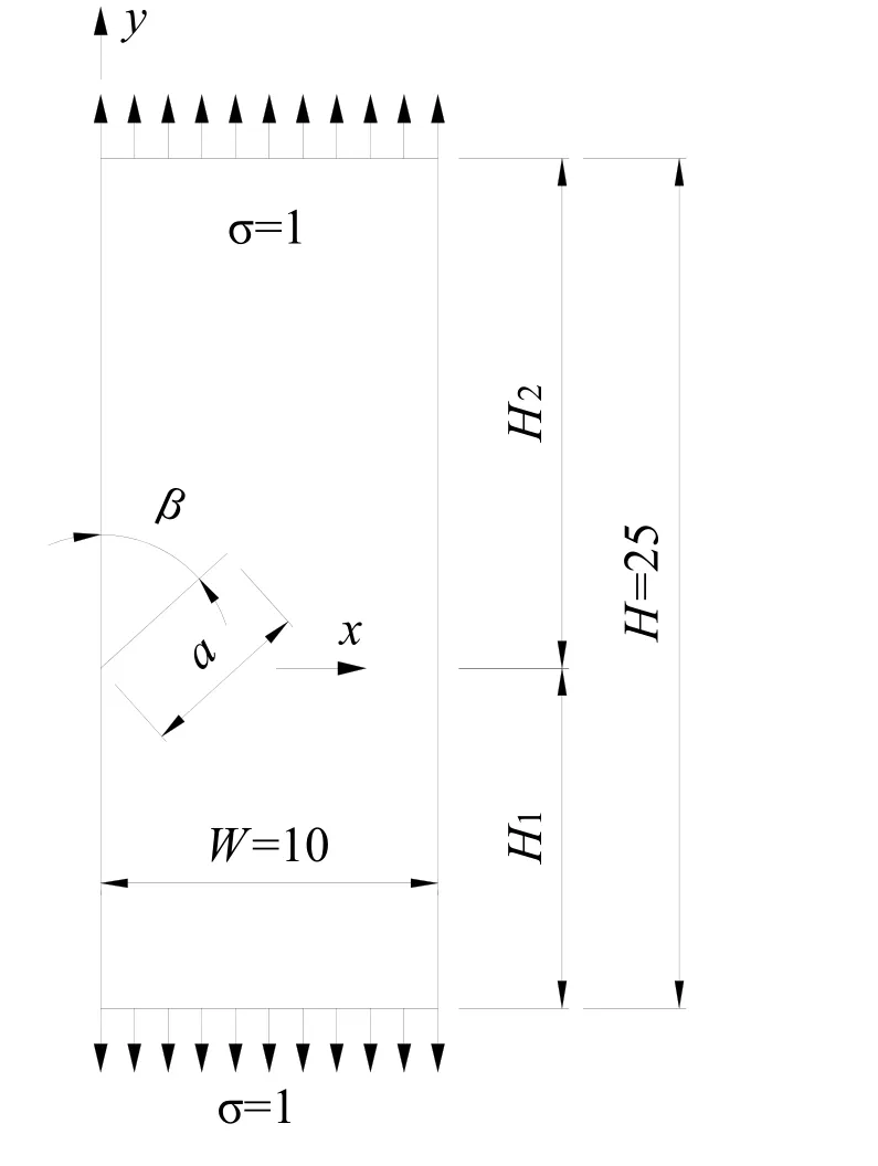
Figure 7: Rectangular plate with a slant single-edge crack
Firstly, results from the experiment [Hedan, Valle and Cottron (2010)] are used to demonstrate the accuracy of the SFBEAM. H1and H2are both taken as 12.5. β and a/W are assumed as 90° and 2.25, respectively. In the SFBEAM, 320 boundary segments, 160 fictitious boundary elements and 800 crack segments are used, as shown in Fig. 8. The non-dimensional SIF by Eq. (24) using the SFBEAM is 1.425 while the result from the experiment in literature [Hedan, Valle and Cottron (2010)] is 1.436. The relative error compared with the experimental result is 0.77%, which indicates that the SFBEAM is of high accuracy.
Then, influence of the crack angle and crack length on SIF is investigated. Let H1=10 and H2=15, different lengths of crack with a/W=0.3~0.6 and different angles of crack with β=45°, β=67.5° and β=90° are considered. In order to compare the accuracy, the elements and segments of “mirroring method” and “Uniform stresses method” are the same. For the former method, the loads on the fictitious crack are symmetric with the loads on the real crack obtained by SFBEM. For the latter method, the loads on the fictitious crack are supposed to be 1. Reference solutions from Chinese Aeronautical Establishment [Chinese Aeronautical Establishment (1981)] are used. The non-dimensional SIFs calculated by Eq.(24) with a0=a is shown in Tab. 1, Tab. 2 and Tab. 3.
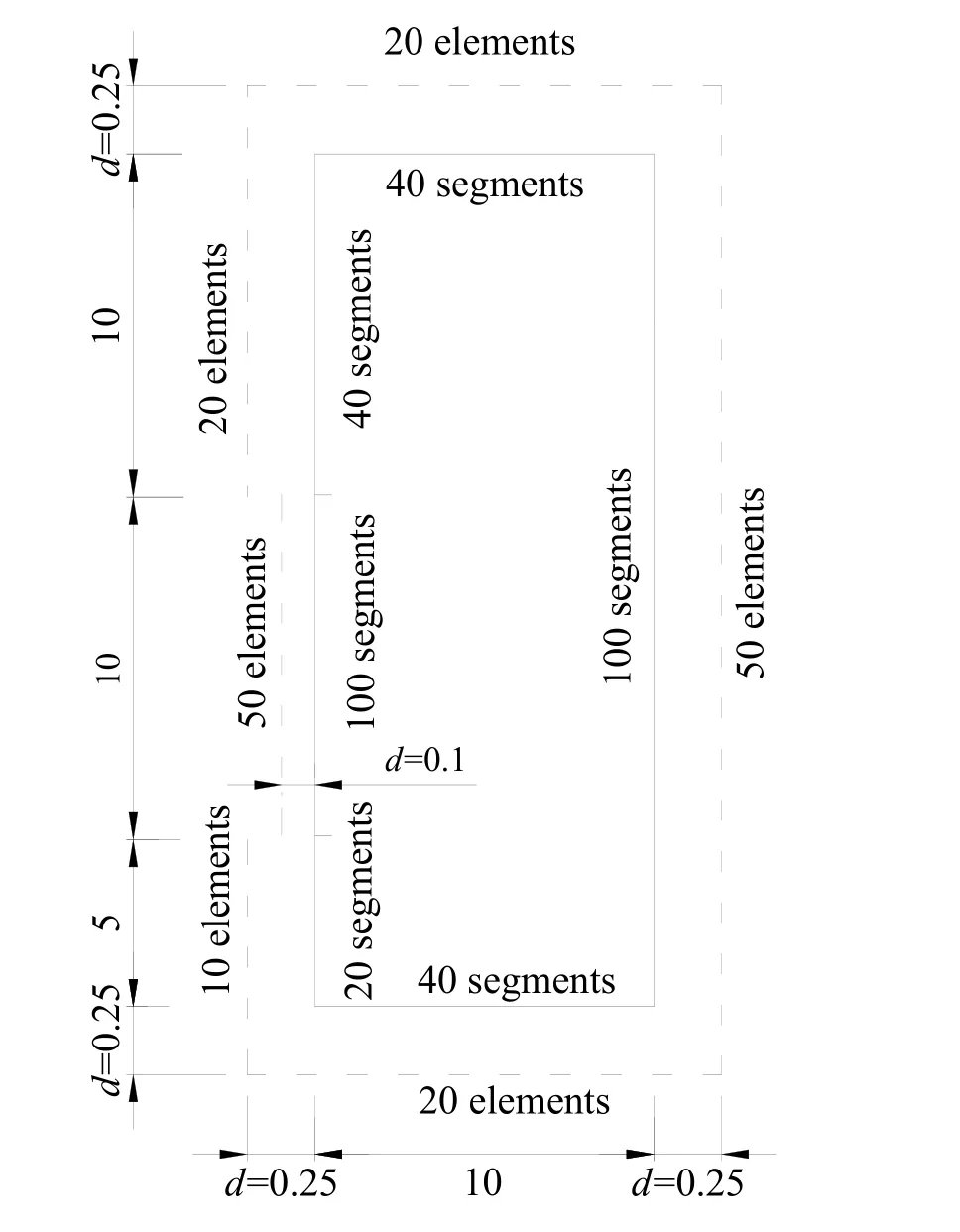
Figure 8: Layout of fictitious boundary
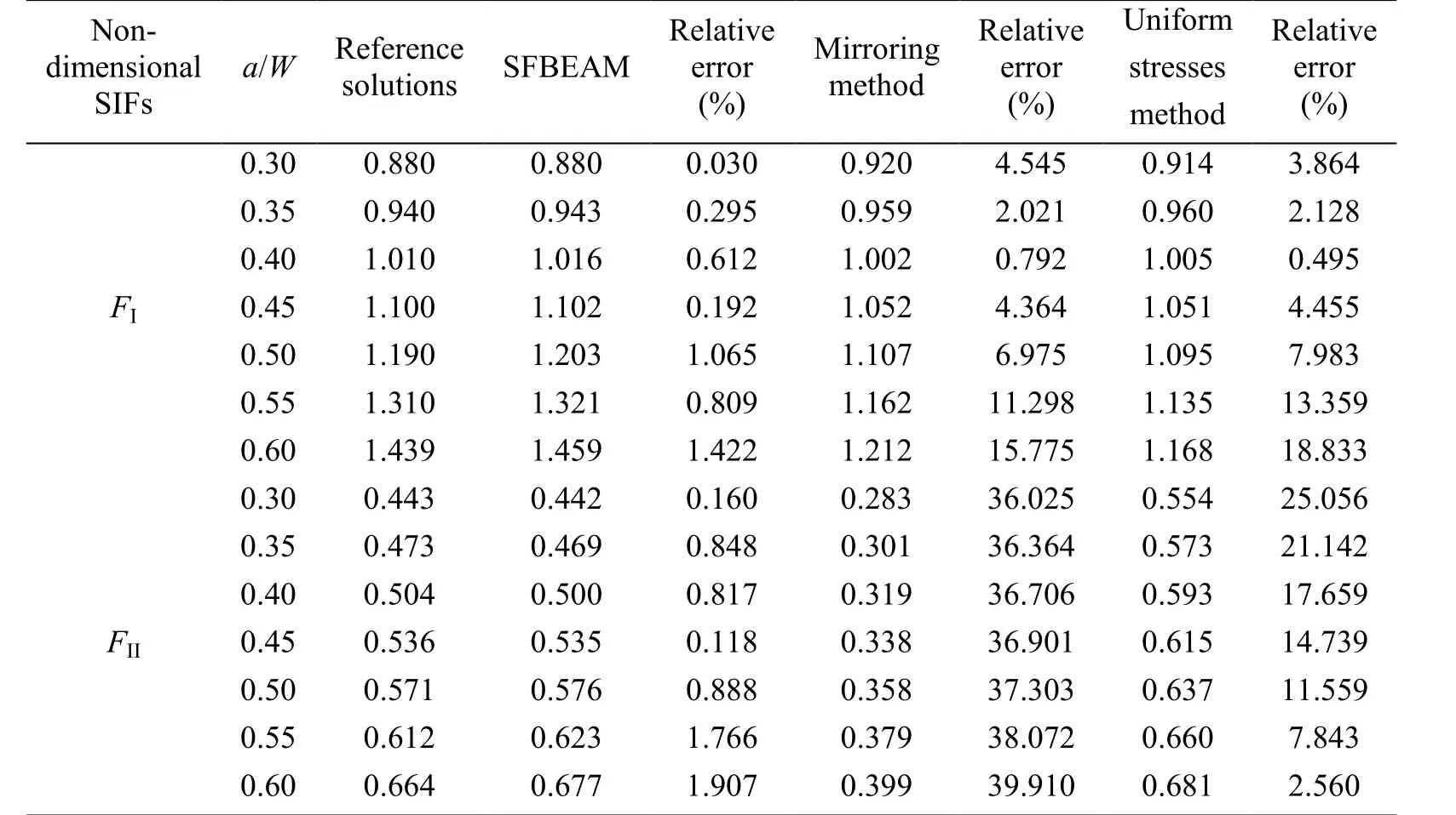
Table 1: Non-dimensional stress intensity factor FI and FII with different crack lengths when β=45°
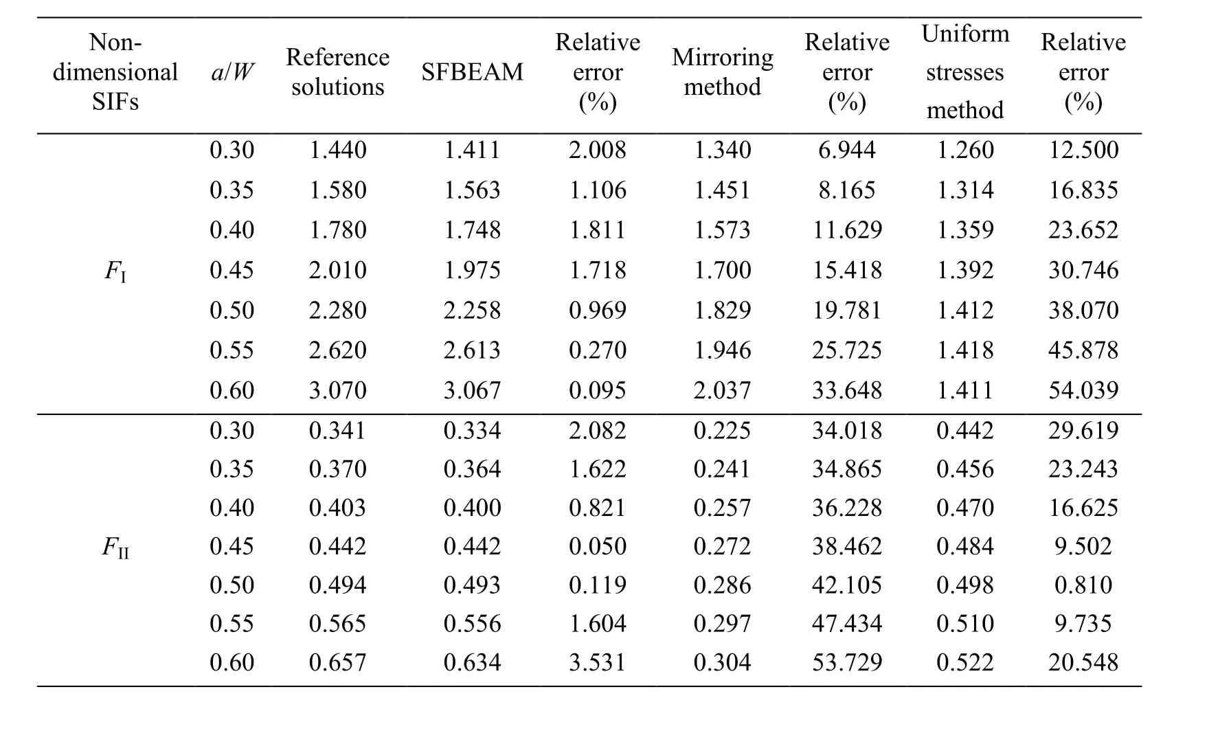
Table 2: Non-dimensional stress intensity factor FI and FII with different crack lengths when β=67.5°
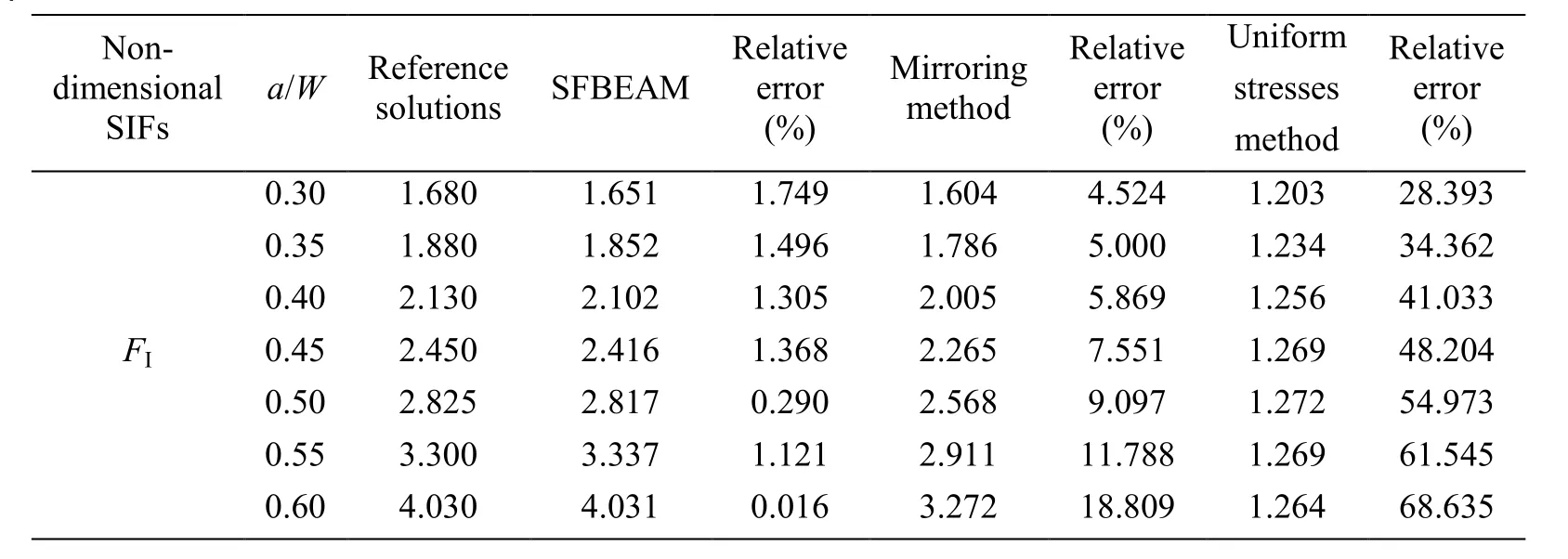
Table 3: Non-dimensional stress intensity factor FI with different crack lengths when β=90°
It can be seen from above that, the calculation results are very far from the reference solutions when using the uniform stresses to simulate the fictitious crack loads. The results by using mirroring method is better than those by using uniform stresses method,but the maximum error of FIis still up to 18.809% and the error of FIIis even up to 53.729%, which means that the accuracy of the mirroring method has not been reached expected. The maximum error of results calculated by SFBEAM are only 2.008%, most of which are below 1%, proving the advantages of SFBEAM. In addition, it can be found that the relative errors of the two methods increase with the increase of the crack lengths,while the results of SFBEAM agree well with the reference solutions. What is more, it is obviously that when the length of the crack increases, the value of non-dimensional SIFs FIand FIIwill increase, and when the crack length remains unchanged and the angle β increases, FIwill increase and FIIwill decrease until FIIto be zero when β=90°.
After discussing the influence of crack angle and crack length on the SIF, the position of the crack becomes another interesting topic. Suppose the length and angle of crack are a=4, β=45° and β=67.5°, respectively. H1is changed from 5 to 20 with an interval of 2.5.The above three methods are also used to solve the problem. The results are shown in Tab. 4 and Tab. 5.
It can be seen from to Tab. 4 and Tab. 5 that, the values obtained by SFBEAM agree well with those of reference solutions, while the results obtained by mirroring method and uniform stresses method have large difference. When H1<15, the values of nondimensional SIFs FIand FIIalmost show no change,but when H1>15, the values of FIincrease sharply as H1increases, while the values of FIIdecrease as H1increases.
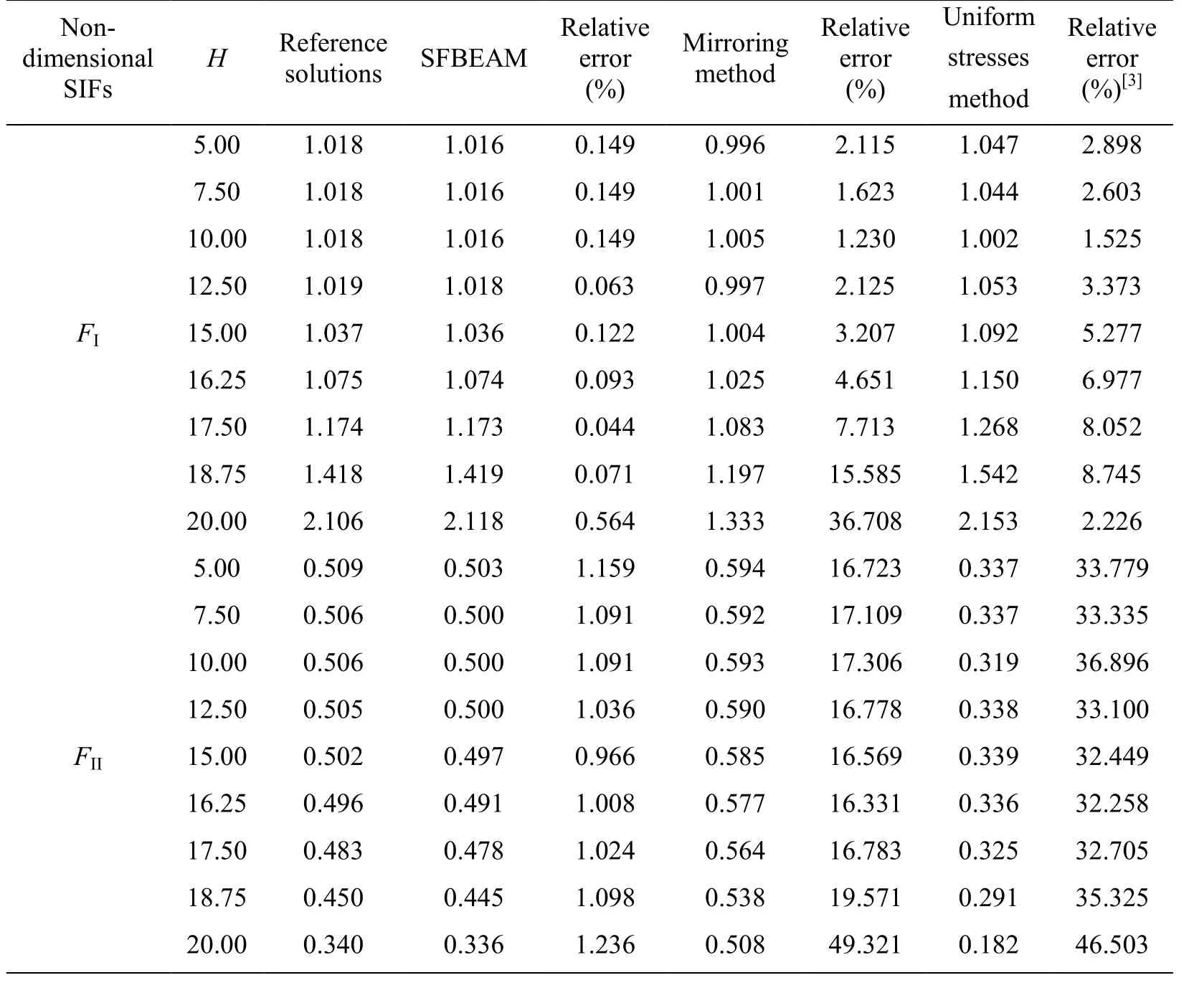
Table 4: Non-dimensional stress intensity factors with different crack position when β=45°
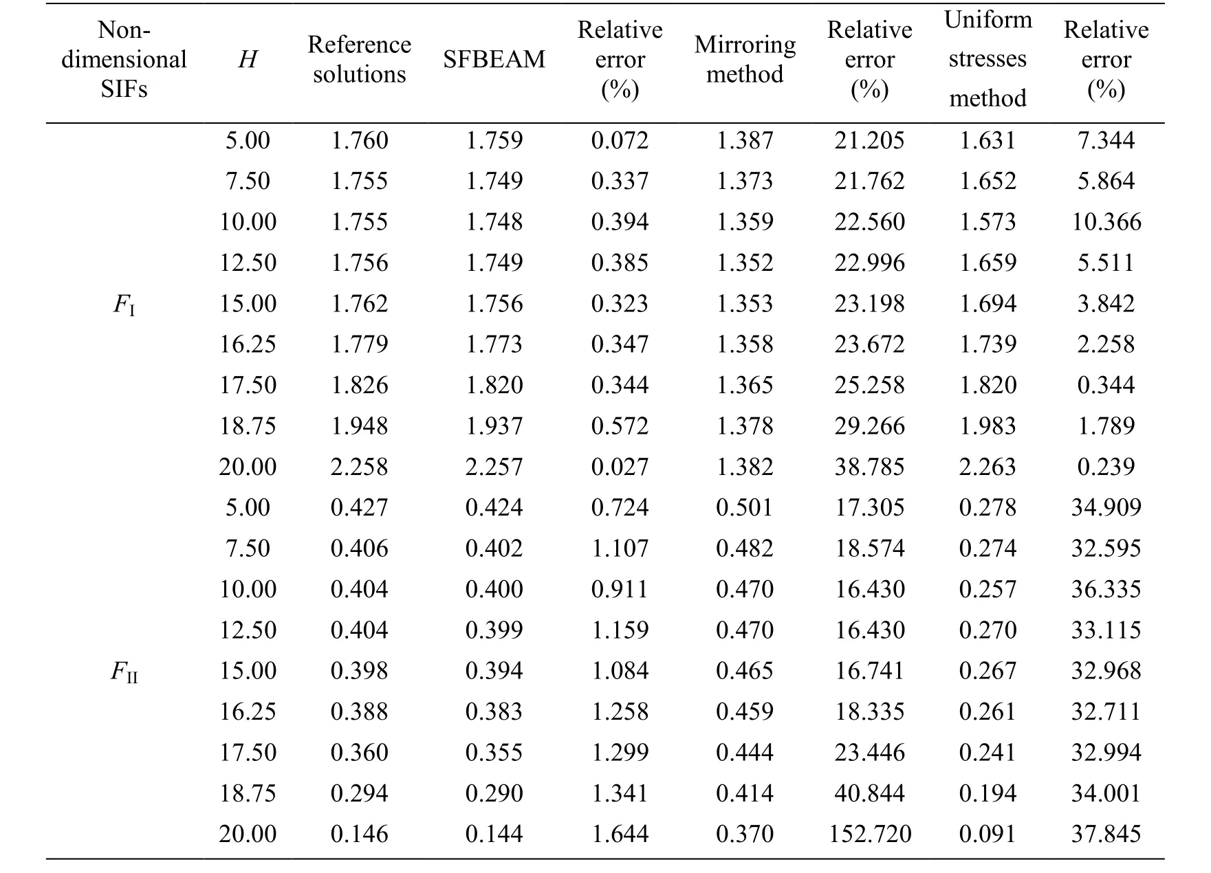
Table 5: Non-dimensional stress intensity factors with different crack position when β=67.5°
3.2 Eccentric tension square plate with an edge crack
A square plate is subjected to two uniformly distributed loads of σ=1, as show in Fig. 9.The plate thickness is assumed to be t=1. Poisson's ratio of the material and the modulus of elasticity are taken as ν=0.2 and E=1000, respectively. The width and height of plate are 2b×2H=20×20. There is a horizontal middle edge on the plate left edge. The distributing length of uniform loads is d.
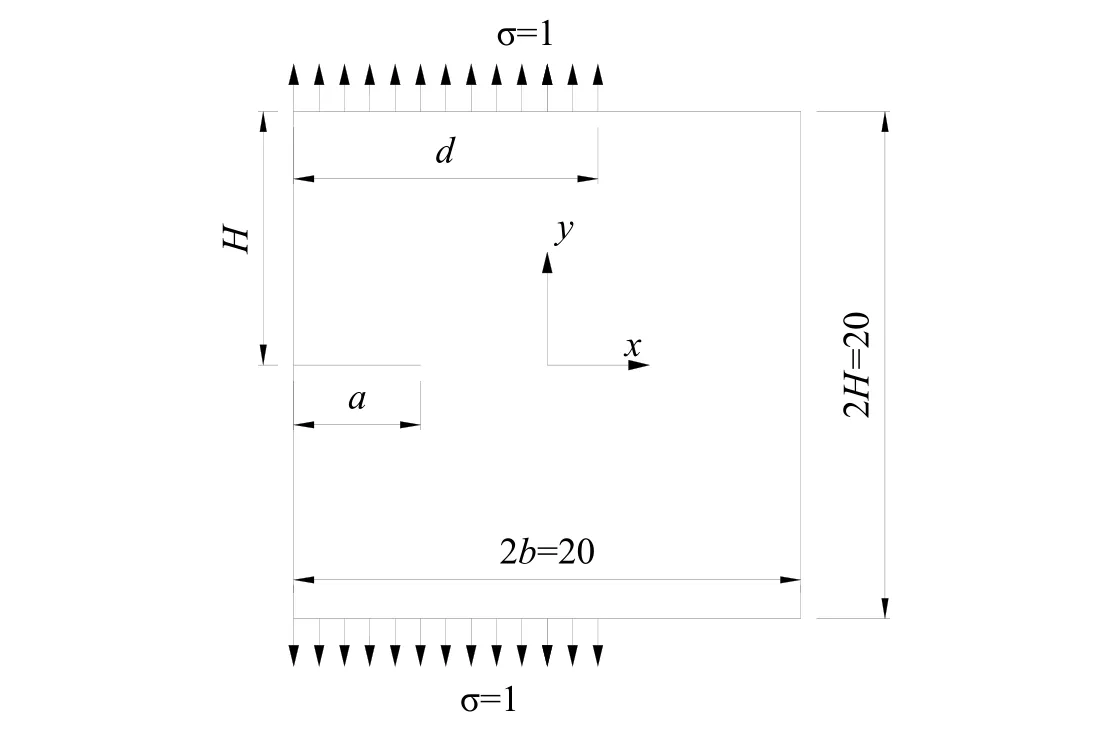
Figure 9: Eccentric tension square plate with an edge crack
The length of the uniform force distribution is considered to be d/2b=0.7 and d/2b=0.3. In each situation, different lengths of crack a/2b=0.1~0.8 are considered. For the purpose of investigating the efficiency of SFBEAM, the XFEM is also used, and the CPU time elapsed by the two methods is recorded respectively. Reference solutions from Chinese Aeronautical Establishment [Chinese Aeronautical Establishment (1981)] are used. Nondimensional SIF can be solved as follow

In SFBEAM, 160 boundary segments, 80 fictitious boundary elements and 800 crack segments are used, as shown in Fig. 10. In XFEM, 800×800 4-node quadrilateral elements are used. The results are shown in Tab. 6.
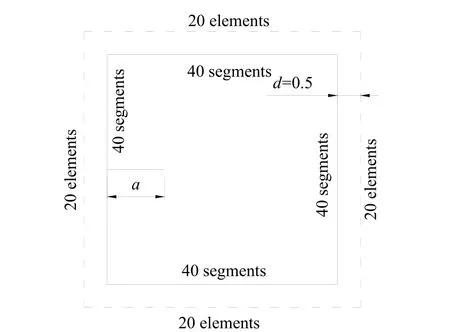
Figure 10: Layout of fictitious boundary
Tab. 6 shows that the results obtained by these two methods agree well with reference solutions. The maximum error of XFEM is 0.947%, while that of SFBEAM is 0.919%.But the computing time of SFBEAM is about 11 s, while that of XFEM is more than 43 s.Besides, with the change of crack length, the computing time changes very small, shows little effect by the crack length. The XFEM has low efficiency, and the computing time increases as the crack length increases, which means the calculation time is greatly influenced by the crack length.
3.3 Square plate with an edge crack under complex boundary conditions
The accuracy of SFBEAM to solve the crack problem with mixed boundary conditions is considered in this example. A square plate with left edge fixed and right one slidesupported, subjected to a uniformly distributed load of σ=1 on top edge, as shown in Fig.11, is analyzed. The plate thickness is taken to be t=1 and Poisson's ratio of the material is assumed to be ν=0.2. The modulus of elasticity is assumed as E=1000 and the size of plate is 2W=20. There is a horizontal edge crack with length a at the middle of right edge of plate.
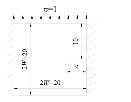
Figure 11: Square plate with an edge crack under complex boundary conditions
The length of crack is a/W=0.1~0.7. In SFBEAM, 200 boundary segments, 100 fictitious boundary elements and 1200 crack segments are used, as shown in Fig. 12. Abaqus is conducted to obtain the reference solutions of the problem, 1/4 singularity elements are used close to the crack tip and 7492 elements are taken for calculation. The results are shown in Tab. 7.
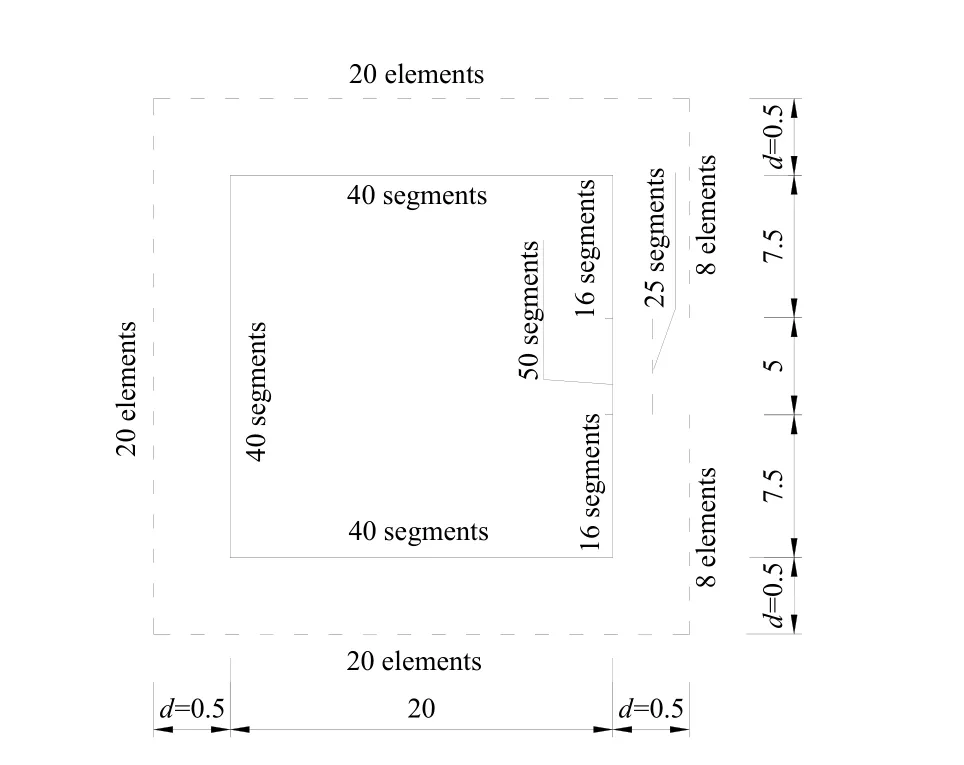
Figure 12: Layout of fictitious boundary
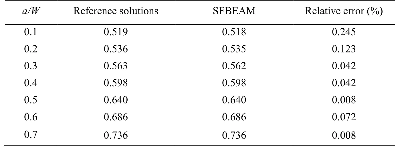
Table 7: Non-dimensional stress intensity factor FI with different crack lengths
Tab. 7 shows that the difference of values of the SIF obtained by the two methods is very small, which proves the effectiveness of SFBEAM in solving the problems with complex boundary condition. And high accuracy can be achieved with small degrees of freedom in SFBEAM. Therefore, the proposed method is superior to solve the crack problem than conventional FEM with lots of freedom of degrees. It can be found that, due to the constraint of the boundary displacement, the values of SIF increase slowly with the increase of the crack length.
3.4 Circular plate with a side crack subjected to uniform load
There is the horizontal edge crack loaded by constant normal σ=1 or constant shear traction τ=1 on the left of a circular plate, as shown in Fig. 13. The plate thickness is taken as t=1 and Poisson's ratio of the material is assumed to be ν=0.2. The modulus of elasticity is assumed as E=1000 and the size of plate is R=10. The length of crack is a.
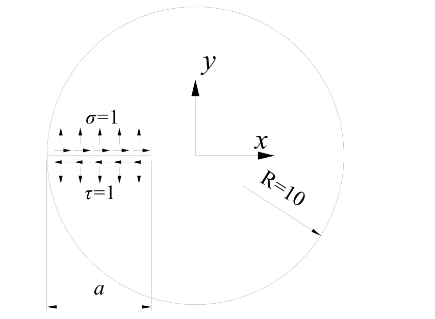
Figure 13: Circular plate with a side crack subjected to uniform load
In SFBEAM, 204 boundary segments, 102 fictitious boundary elements and 800 crack segments are used, as shown in Fig. 14. The results with different length of crack are obtained, and reference solutions from references [Chinese Aeronautical Establishment(1981)] and [Fett (2002)] are used. The results are shown in Tab. 8 and Tab. 9.
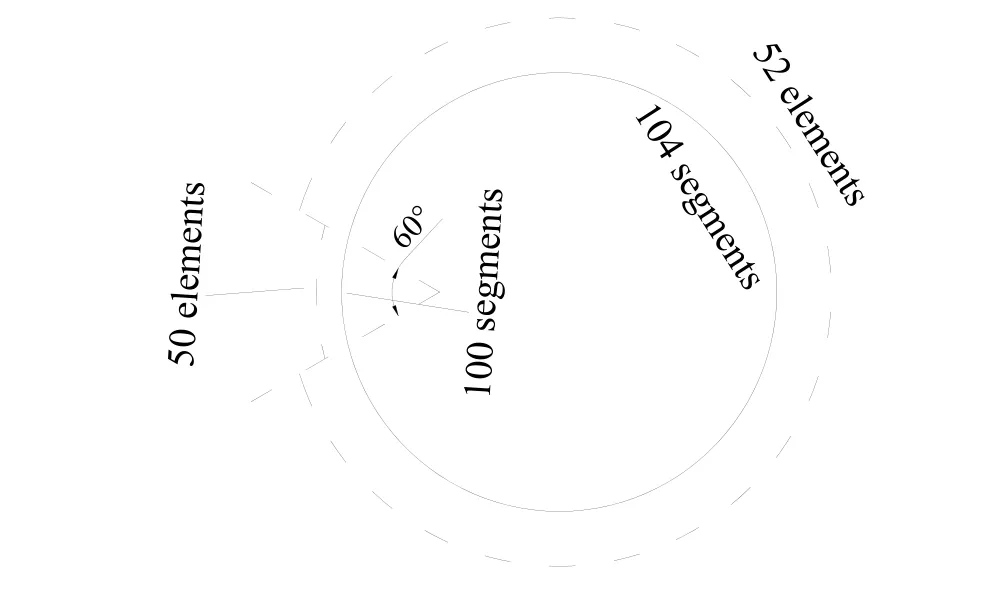
Figure 14: Layout of fictitious boundary

Table 8: Non-dimensional stress intensity factor FI when σ=1
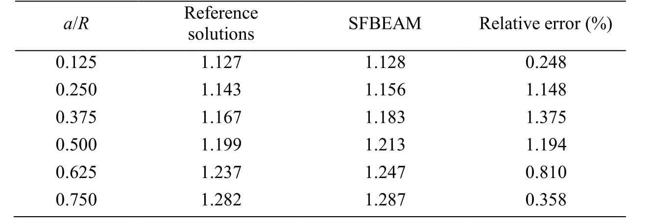
Table 9: Non-dimensional stress intensity factor FII when τ=1
Comparing the results obtained by different methods, it is found that the maximum error of FIis only 0.585%, and the maximum deviation of FIIis only 1.375%, which shows that the SFBEAM has high accuracy and is applicable to the problems with loads on the crack.
4 Conclusion
In this paper, the spline fictitious boundary element alternating method (SFBEAM) for solving the edge crack problem is presented with the combination of the SFBEM and the Muskhelishvili's solutions based on the infinite domain. Compared with other alternating methods, Because the SFBEM and Muskhelishvili's solutions are formulated in the infinite domain, no special treatments are needed for solving the problem of edge crack.Besides, with the locally thickened technique close to the crack tip meshes, the solving efficiency is improved. The SIF solutions of a rectangular plate with a slant single-edge crack and an eccentric tension square plate with an edge crack are discussed. The advantage of high precision of the SFBEAM is verified compared with other two alternative methods and the advantage of high efficiency of SFBEAM is verified compared the extended finite element method using their CPU results. In addition, the method is also applied to solve a square plate with an edge crack under mixed boundary conditions and a circular plate with a side crack subjected to uniform load on the crack surface, and the results show that the method is of high accuracy and have the strong adaptability to the mixed boundary conditions edge crack problems.
Acknowledgments:This research was supported by the National Natural Science Foundation of China (51078150), the National Natural Science Foundation of China(11602087), the State Key Laboratory of Subtropical Building Science, South China University of Technology (2017ZB32) and National Undergraduate Innovative and Entrepreneurial Training Program (201810561180).
 Computer Modeling In Engineering&Sciences2018年9期
- Computer Modeling In Engineering&Sciences的其它文章
- Improved State-Based Peridynamic Lattice Model Including Elasticity, Plasticity and Damage
- Eddy Current Analyses by Domain Decomposition Method Using Double-Double Precision
- Machining Parameters Optimization of Multi-Pass Face Milling Using a Chaotic Imperialist Competitive Algorithm with an Efficient Constraint-Handling Mechanism
- UPFC Based Real-Time Optimization of Power Systems for Dynamic Voltage Regulation
- A Computer-Aided Tuning Method for Microwave Filters by Combing T-S Fuzzy Neural Networks and Improved Space Mapping
- Effect of Plaque Composition on Biomechanical Performance of a Carotid Stent: Computational Study
