Numerical analysis of Shiobara hydro power cavern using practical equivalent approach
V.B.Maji
Department of Civil Engineering,Indian Institute of Technology Madras,Chennai,India
1.Introduction
Rocks are different from other engineering materials due to the presence of flaws and weak planes,and stress and deformation responses of rock masses induced mostly by the discontinuities.Reliable characterisation of strength and deformation behaviours of jointed rocks is important for safety design of any rock engineering structures.Evaluation of strength and deformation characteristics of rock mass is a challenging issue.Moreover,with the large number of joints,it becomes almost impossible to deal with each joint individually.In this case,it is necessary to replace the jointed rock mass with an equivalent body with an appropriate constitutive model.Several numerical methods have been developed by various researchers to model jointed rock masses.Singh(1973)presented continuum characterisation methods for jointed rock masses to estimate the elastic modulus of equivalent continuum anisotropic rock mass.Zienkiewicz and Pande(1977)used the equivalent continuum approach known as multi-laminate model to simulate a discontinuous rock mass.Many other researchers,e.g.Amadei and Goodman(1981),Gerrard(1982),Fossum(1985),Kawamoto et al.(1988),Chen(1989),Cai and Horii(1992),Desai and Ma(1992),Oda et al.(1993),Zhu and Wang(1993),Wei and Hudson(1998),Adhikary and Dyskin(1998)and Hao et al.(2002),developed their own rock mass models.Recently,Sakurai(2010)developed a modelling strategy for jointed rock masses reinforced with rock bolt for tunnels.Xu et al.(2015)reviewed and developed a new elasto-plastic constitutive model for jointed rock mass.Gonzalez et al.(2016)highlighted the comparison of discrete and equivalent continuum approaches to simulate the mechanical behaviours of jointed rock masses.
An equivalent continuum approach proposed by Sitharam et al.(2001,2007),Sitharam and Latha(2002),and Latha and Garaga(2012)is found to be an effective tool for modelling jointed rock mass.The implementation of this simple equivalent continuum approach has been attempted in the programme fast Lagrangian analysis of continua in three dimensions(FLAC3D)(Sitharam et al.,2007).The details of the approach including the basic steps adopted and the verification exercise results are presented in the earlier publications(e.g.Sitharam et al.,2007).The verification of the equivalent model is carried out by conducting uniaxial and triaxial tests numerically and comparing with the respective laboratory results.The verification programme includes laboratory tested cylindrical specimens of different rock types with 1-4 joints at different orientations,subjected to varying confining pressures.The results were also compared with those obtained from explicit modelling of the cases where joints were incorporated as interfaces in the model.To represent the highly discontinuous system,the laboratory investigation on block jointed specimens of gypsum plaster(Brown and Trollope,1970)is numerically modelled.The applicability of the model is demonstrated by modelling and analysing Shiobara hydropower cavern project using the code FLAC3D.
2.Description of the model
The model is proposed based on the relationships that are simple and easy to be derived on the basis of a large number of laboratory tests on jointed rock masses.The material properties are expressed with joint factor(Jf)(Ramamurthy,1993)and the properties of the intact rock.The elastic modulus ratio(Er)for the rock mass,which is defined as the ratio of elastic modulus of the jointed rock(Ej)to that of the intact rock(Ei),can be calculated using the following exponential function of joint factor(Jf):

The compressive strength ratioσcr,defined as the ratio of the uniaxial compressive strength(UCS)of the jointed rock(σcj)to that of the intact rock(σci),is written as

The rock mass modulus in the unconfined state is related to the confined state by the following expression(Ramamurthy,1993):

The stress-strain behaviour was represented by a confining pressure-dependent hyperbolic relation by Duncan and Chang(1970).The hyperbolic model expression for instantaneous slope of the stress-strain curve,i.e.the tangent modulusEt,is given as follows:

Fig. 1.Dependency of nonlinearity in the stress-strain behaviour on the failure ratio(Rf).
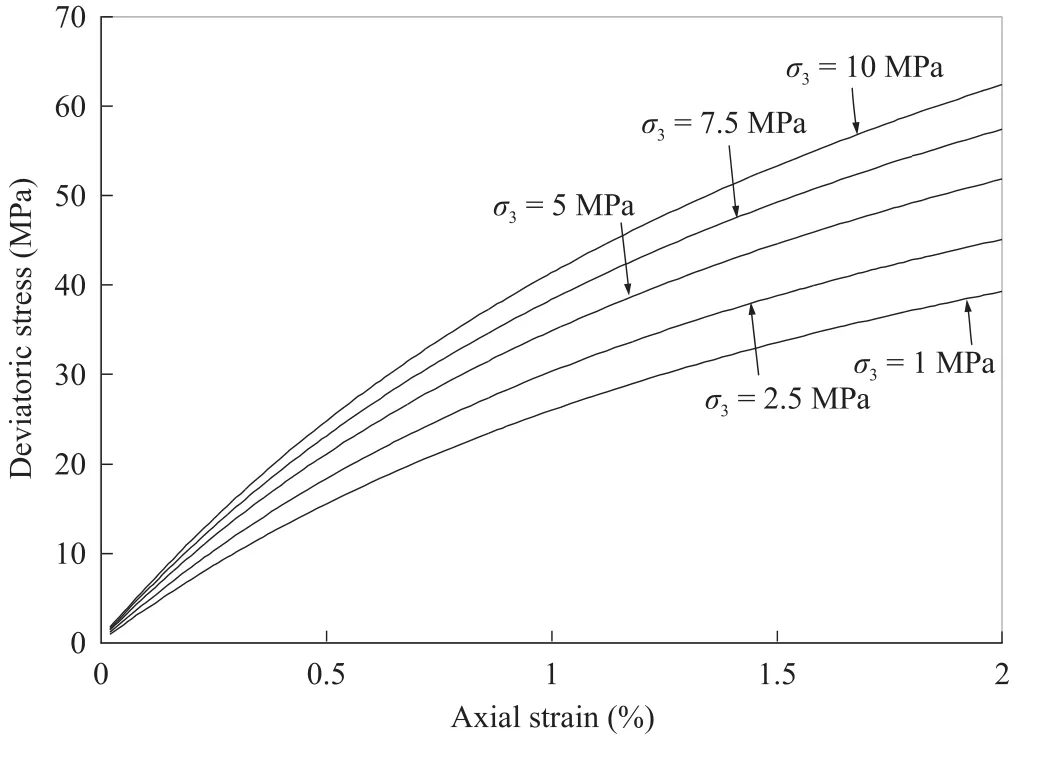
Fig. 2.influence of confining stress on the stress-strain behaviour.

whereKis the modulus number,nis the modulus exponent,cis the cohesion,φis the angle of internal friction,andRfis the failure ratio.
The approach has been incorporated in the form of material nonlinearity with incremental method in the explicit finite difference code FLAC3D(Sitharam et al.,2007).The FISH functions were written to incorporate the joint factor model along with the Duncan and Chang(1970)’s nonlinear hyperbolic relation that calculates nonlinear elastic moduli as a function of confining pressure.The nonlinearity of the material behaviour was efficiently captured in the numerical model using failure ratio(Rf)(Fig. 1).In the analysis,Rfvalues were chosen as per the nonlinearity in the stress-strain behaviour.With increasing confining pressure,the effect of jointing nullif i es and the stress-strain curve is expected to become relatively linear.If the confining pressure is kept constant or varies in a small range,error due to the constantRfcan be minimised.influence of confining pressure on the stress-strain behaviour while keepingRfconstant is shown in Fig. 2.The nonlinear stress strain behaviours captured using FLAC3D and axi-symmetric FLAC for a jointed rock mass are shown in Fig. 3(Itasca,1999,2001).
3.Model verification using FLAC3D

Fig. 3.Stress-strain curves obtained from numerical tests with those from FLAC3D and axi-symmetric FLAC.
A systematic verification of the equivalent continuum model is attempted by conducting numerical triaxial tests,and comparing with the respective laboratory experiments(Sitharam et al.,2007).Numerical tests on jointed rocks with 1-4 joints in different orientations,subjected to varying confining pressures,were carried out.The results were compared with those obtained from laboratory experiments and also the explicit model.To represent highly discontinuous system,laboratory tests on block jointed specimens of gypsum plaster(Brown and Trollope,1970)were modelled numerically(Sitharam et al.,2007)(Fig. 4).Intact rock properties of Jamrani sandstone are given in Table 1.Fig. 5 shows the deviatoric stress ratio versus joint inclination at two different confining pressures.It can be seen that the failure stress is the lowest when the joint inclination β ranges between 30°and 40°,and it increases with the confining pressure.It is understood that the failure stress of the rock mass is influenced by the joint orientation and confining pressure.The rock specimen has the highest strength whenβis close to 0°and 90°,and the least strength when β is around 30°(Maji and Sitharam,2012).
Explicit modelling of jointed rock specimens have also been carried out to know the efficiency of the equivalent model(Sitharam et al.,2007).Modelling has been conducted on single jointed specimens of Agra and Jamrani sandstones with inclinations of 45°and 60°at confining pressures of 1 MPa,2.5 MPa and 5 MPa.Multiple jointed rock specimens of Jamrani sandstone having 1,2,3 and 4 joints with β=70°and 90°were also selected.The results of the explicit modelling with FLAC3D have been plotted with the actual experimental results together with the equivalent modelling results.Joint frequency(Jn)was found to have a significant influence on the strength and deformation behaviours of rocks;with increasing joint frequency,there is always a reduction in peak axial stress.Fig. 6 shows the variation of compressive strength ratioσcrwith the joint frequency(Jn)for Jamrani sandstone with 90°joint inclination.The numerical results from FLAC3D were found to have close agreement with the actual experimental results.It is observed that the strength is reduced with increasing joint frequency,but the rate and the magnitude of reduction are larger than those for the cases where the joint inclination with respect to the major principal stress direction is close to 30°-50°.The strength increase with increasing confining pressure was also clearly observed.

Fig. 4.Comparison of equivalent continuum modelling results with those from experiments(Brown and Trollope,1970)for 60°/30° block jointed specimens at four different confining pressures(Sitharam et al.,2007).

Table 1Properties of intact rocks used for the numerical modelling.

Fig. 5.Variation of deviatoric stress ratio with joint inclination for Jamrani sandstone with a single joint.
4.Case study of Shiobara hydropower cavern
4.1.Shiobara hydropower cavern
The applicability of the model to field problems is demonstrated by undertaking numerical modelling of a powerhouse cavern using FLAC3D.The Shiobara hydropower cavern located at Tochigi prefecture about 130 km north of Tokyo,Japan is considered as a case study.The project has a large cavern for the pumped storage power station with a maximum output of 900 MW(300 MW×3 units).The cavern has a width of 28 m,a height of 51 m,a length of 161 m,and an excavation volume of more than 190,000 m3.An outline of the cavern is shown in Fig. 7 with transformer house and service tunnels and also the locations of displacement transducers.The rock surrounding the powerhouse is mainly rhyolite with platy and columnar joints.Joint sets having their strikes parallel to the cavern axis are considered to be dominant joint sets.The dip angles of the dominant joint sets are found to be 30°/60°to the left and 60°to the right.The average spacing of the joints has been reported to be 0.3-1 m,with average values of 0.3 m for the joint set whose dip is 60°to the right and 1 m for the joint sets with dips of 30°and 60°to the left(Yoshida and Horii,2004).Additional details on the project and the geology may be found in Yoshida and Horii(1998,2004).The elastic modulus of rock mass is 2900-5100 MPa,the cohesion is 1.02 MPa,and the angle of internal friction is around 43°.The axial compressive strength is found to be 58.8-137.2 MPa,with an average value of 83.3 MPa.The cavern is at a depth of 200 m and the three principal stresses are 5 MPa,3.9 MPa and 2.8 MPa,respectively.The details on the properties are listed in Table 2.The hyperbolic model properties are derived using numerical triaxial testing and fitting curve to elasto-plastic solution using trials.
4.2.Analysis procedure

Fig. 6.Variation of compressive strength ratio(σcr)with joint frequency(Jn)for Jamrani sandstone having 90°joint inclination.
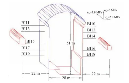
Fig. 7.Outline of the cavern and locations of multi-point borehole extensometer for the cavern of Shiobara hydropower station.

Table 2Properties used for the rock of Shiobara hydropower cavern.
The equivalent approach is used for three-dimensional(3D)stress and deformation analyses of the powerhouse cavern with simulation of staged excavation.The modelling results were compared with the instrumented data and also with the results of six other computation models(Horii et al.,1999)that were used to analyse the cavern.The 3D finite difference mesh of the caverns is shown in Fig. 8.Fig. 9 shows the FLAC3D mesh for the caverns with boundaries.The total numbers of the zones considered and the grid points(nodes)are 13,060 and 13,944,respectively,of which 3507 grid points and 2880 zones represent the tunnels(portion to be excavated,Fig. 8).The total volume considered for the simulation is 240 m×200 m×161 m with four different types of 3D elements,namely brick,cylinder,rad-cylinder(radially graded mesh around cylindrical-shaped tunnel)and cshell(cylinder shell mesh)(Itasca,2001).As shown in Fig. 9,only 86 m overburden is modelled and the rest 114 m overburden is taken into consideration by applying equivalent amount of pressure at the top to save computational time and effort.As the deformation induced byan advancing tunnel is a 3D problem,the excavation steps are attempted to be simulated in the numerical analysis.The displacements at the extensometer locations are recorded and compared with those measured by the multi-point borehole extensometer(MPBX).The cavern is excavated in five segments,about 32 m in the length of excavation per segment.Each segment is excavated in six stages in top-down excavation schemes(Fig. 10).The variation of displacements with different stages of excavation is obtained from numerical analysis by solving equilibrium after each excavation stage.As the surrounding rocks around the cavern are jointed,this reduces the stiffness of the rock mass,leading to excessive settlements due to the excavations.This study attempts to capture the behaviour and settlements numerically and presents the corresponding results.
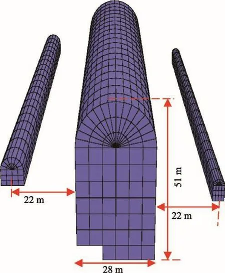
Fig. 8.FLAC3D model of Shiobara powerhouse cavern:underground openings.
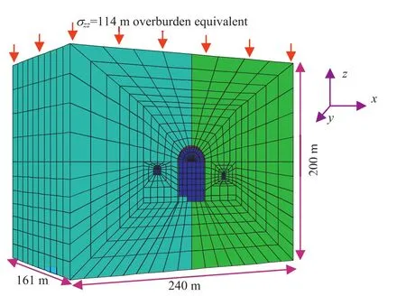
Fig. 9.FLAC3D mesh of Shiobara hydropower cavern with complete boundaries.
4.3.Analysis results

Fig. 10.Complete excavation scheme using null model available in FLAC3D.
The equivalent model implemented in the commercial finite difference code FLAC3D is used for the simulation of the cavern.MPBX data are available at several locations along different measurement lines BI10 to BI19(Fig. 7)around the cavern.Six point extensometers are fixed at depths of 1.5 m,3 m,5 m,10 m,15 m and 20 m.Initial stresses representing the in situ stresses around the power station cavern are applied and the displacements around the outer boundary are fixed.The hyperbolic properties of cavern rock are provided in Table 2.The cavern along with the surrounding rock has been analysed after the completion of each stage of excavation using the null model available in FLAC3D(Fig. 10).Each stage of excavation is divided into six sub-stages.The displacements measured along all the measurement lines are available in different stages of excavation of the cavern(Horii et al.,1999).It was observed that the critical joint set significantly influences the behaviour of the cavern and varies with the location under consideration,resulting in asymmetry in deformations.The dip angles of the dominant joint sets are found to be 30°and 60°to the left and 60°to the right.It is to be mentioned that the joint set I,which has smaller spacing,is critical for the right side of the cavern;as for the left side,the joint set III with an inclination angle of 30°is critical.Thus,considering only one set of joints cannot capture the asymmetry in deformations.In the present study,the influence of two different joint sets are simulated by considering a joint factor(Jf)value of 41 for the right portion of the cavern and aJfvalue of 111 for the left portion.This variation ofJfin two different sides of the cavern is incorporated in the model using FISH function.The displacements at corresponding MPBX locations after the final stage of excavation along the measurement lines BI10,BI11,BI16 and BI17 were recorded.The numerical displacements are compared with the actually measured values,as shown in Fig. 11.It is observed from the results that the predicted values of displacements are generally larger than the measured values,which may be attributed to the use of support system in the field.
4.4.Analysis with support system
The support system of the cavern consists of pre-stressed(PS)anchors,rock bolts,arch concrete and shotcrete.In the present study,to reduce excessive settlements,two types of support systems,namely shotcrete and concrete lining,were adopted.The shotcrete was modelled with liner-shell structural elements while the concrete lining was modelled with zones that are assigned properties representing the lining material.The lining material replaces the rock mass after the corresponding stage of excavation.The lining components are modelled as elastic materials with elastic modulus(E)of 31.4 GPa and Poisson’s ratio(ν)of 0.25.The concrete liner has been created using cshell zones behind the advancing cavern.The liner-zone interface stiffnessesknandksare both taken as 7.4×10¹⁰N/m3to ensure that the interface deformation is small relative to the zone deformation.The cavern is also supported by shotcrete with a thickness of 0.2 m.The shotcrete has been installed by creating liner-elements SELs,which have been attached to the cavern surface with SEL-liner command available in FLAC3D.The shotcrete support has been extended into the cavern excavation stage 2,by issuing another liner-SELs command and specifying an ID number that differs from the ID number of SEL in cavern stage 1.This creates a “cold joint”between two adjacent shotcrete segments(Itasca,2001).The deformation that occurs during stage 3 begins to load the new SEL segment and produces additional load in the previous SEL segment.The shotcrete is modelled as an elastic material with the elastic modulus of 10.5 GPa and Poisson’s ratio of 0.25.Numerical analyses of the cavern with concrete liner and shotcrete support using FLAC3D were found to be very effective in reducing the overall deformations.The close-up view of the cavern with concrete liner and shotcrete support used in this analysis is shown in Fig. 12.Tables 3 and 4 present the displacement values along measurement lines BI10,BI11,BI16 and BI17 for both with and without support system,together with the measured deformation(Horii et al.,1999).It can be observed that the use of supports significantly reduces the displacement values.
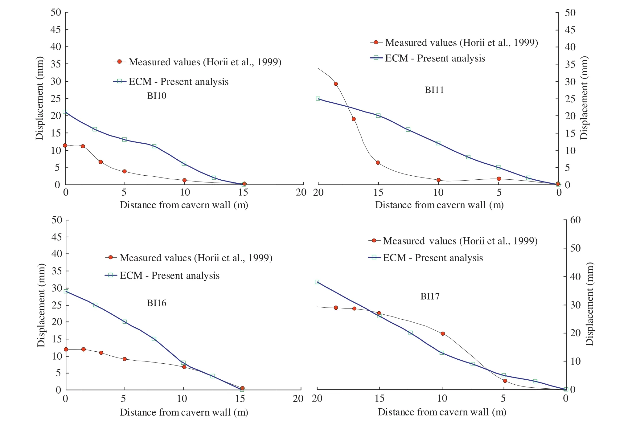
Fig. 11.Comparison of relative displacements along the measurement lines.

Fig. 12.Close-up view of the cavern face with supports of(a)concrete liner,and(b)shotcrete(after first stage of excavation).
4.5.Comparison with other computational models
The results obtained from the above analysis were also compared with those of six other computation models(Horii et al.,1999)which were applied to the same cavern,as shown in Fig. 13.This work was an international effort to develop an analysis
method that can accurately predict the behaviour of rock mass during excavation.These six models are NAPIS(strain-softening analysis considering joint failure),micro-mechanics based continuum model(MBC)(Yoshida and Horii,1998),the equivalent rock analysis(EQR),multiple yield model,the crack tensor model(Oda etal.,1993),and the damage tensor model developed by Kawamoto et al.(1988).Fig. 13 also shows the Horii et al.(1999)curves for comparison purpose.In this figure,it is evident that the present simple approach could capture the deformation behaviour of rock mass and compare well with the measured values.The results are also comparable with those of other six computational models,indicating that the equivalent approach is efficient in simulating the excavation stage and asymmetry in displacements due to anisotropy in the variation in joints.The left side(BI11 and BI17)of the cavern was found to show relatively higher displacements than the right side(BI10 and BI16)due to higher joint frequency.This appears to be convincing with the deformation of joints,which reduces the stiffness of the rock mass,similar to that exactly recorded during measurements.These results also support the use of present simple analysis method for large-scale field problems in jointed rocks.

Table 3Displacement values along measurement lines BI10 and BI11.

Table 4Displacement values along measurement lines BI16 and BI17.
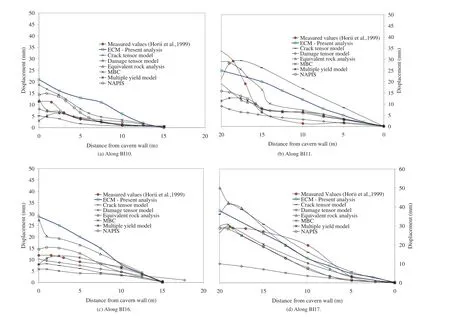
Fig. 13.Comparisons of relative displacements along different measurement lines.
5.Conclusions
The simple approach for modelling jointed rocks integrates the effect of joints on the strength and deformation characteristics.The model requires minimum inputs from field or laboratory tests and is found to be efficient to capture the deformation behaviour of rocks with any degree of nonlinearity.The equivalent model is implemented in the commercial finite difference code FLAC3D with the help of FISH functions and is systematically validated.The applicability of the model to the field problems is investigated with the analysis of Shiobara hydropower cavern.Excavation stages and deformation behaviour of the cavern could be captured realistically with the help of numerical model.MPBX data available at several locations along measurement lines BI10 to BI19 around the cavern were used for comparison.The numerical results were also compared with those of six other computational models which were earlier used to analyse the same cavern.The model,though simple and having minimum inputs,predicted the deformation values well,and the study confirmed the effectiveness of the approach for simulating large-scale underground structures in jointed rocks.
Conflict of interest
The author wishes to confirm that there are no known Conflicts of interest associated with this publication and there has been no significant financial support for this work that could have influenced its outcome.
Acknowledgements
The author thanks his PhD supervisor Prof.T.G.Sitharam in the Department of Civil Engineering,Indian Institute of Science(IISc),Bangalore,India.Many of the results presented were carried out at IISc,as part of the author’s PhD work.
Adhikary DP,Dyskin AV.A continuum model of layered rock masses with nonassociative joint plasticity.International Journal for Numerical and Analytical Methods in Geomechanics 1998;22(4):245-61.
Amadei B,Goodman RE.A 3D constitutive relation for fractured rock masses.In:Selvadurai APS,editor.Proceedings of the international symposium on the mechanical behavior of structured media,Part B.Ottawa,Canada;1981.p.249-68.
Arora VK.Strength and deformation behaviour of jointed rocks.PhD Thesis.Delhi,India:Indian Institute of Technology;1987.
Brown ET,Trollope DH.Strength of a model of jointed rock.Journal of the Soil Mechanics and Foundation Division,ASCE 1970;96(2):685-704.
Cai M,Horii H.A constitutive model of highly jointed rock masses.Mechanics of Materials 1992;13(3):217-46.
Chen EP.A constitutive model for jointed rock mass with orthogonal sets of joints.Journal of Applied Mechanics 1989;56(1):25-32.
Desai CS,Ma Y.Modelling of joints and interfaces using disturbed state concept.International Journal for Numerical and Analytical Methods in Geomechanics 1992;16(9):623-53.
Duncan JM,Chang CY.Nonlinear analysis of stress and strain in soil.Journal of the Soil Mechanics and Foundation Division,ASCE 1970;96(5):1629-53.
Fossum AF.Effective elastic properties for a randomly jointed rock mass.International Journal of Rock Mechanics and Mining Sciences&Geomechanics Abstracts 1985;22(6):467-70.
Gerrard CM.Elastic models of rock masses having one,two and three sets of joints.International Journal of Rock Mechanics and Mining Sciences&Geomechanics Abstracts 1982;19(1):15-23.
Gonzalez NA,Vargas PE,Carol I,Das KC,Sandha SS,Rodrigues E,Mello U,Segarra JMS,Lakshmikantha RM.Comparison of discrete and equivalent continuum approaches to simulate the mechanical behavior of jointed rock masses.In:Wuttke F,Bauer S,Sanchez M,editors.Energy geotechnics:proceedings of the 1st international conference on energy geotechnics(ICEGT 2016),Kiel,Germany.London:Taylor&Francis Group;2016.
Hao H,Wu C,Zhou YX.Numerical analysis of blast-induced stress waves in a rock mass with anisotropic continuum damage models.Part 1:equivalent material property approach.Rock Mechanics and Rock Engineering 2002;35(2):79-94.
Horii H,Yoshida H,Uno H,Akutagawa S,Uchida Y,Morikawa S,Yambe T,Tada H,Kyoya T,Fumio I.Comparison of computational models for jointed rock mass through analysis of large scale cavern excavation.In:Proceedings of the 9th International Congress on Rock Mechanics,vol.1.Paris,France:International Society for Rock Mechanics(ISRM);1999.p.389-93.
Itasca.Fast Lagrangian analysis of continua(FLAC)user’s manuals,version 4.Minneapolis,USA:Itasca Consulting Group,Inc.;1999.
Itasca.Fast Lagrangian analysis of continua in 3 dimensions(FLAC3D)user’s manuals,version 2.1.Minneapolis,USA:Itasca Consulting Group,Inc.;2001.
Kawamoto T,Ichikawa Y,Kyoya T.Deformation and fracturing behavior of discontinuous rock mass and damage mechanics theory.International Journal for Numerical and Analytical Methods in Geomechanics 1988;12(1):1-30.
Latha GM,Garaga A.Elasto-plastic analysis of jointed rocks using discrete continuum and equivalent continuum approaches.International Journal of Rock Mechanics and Mining Sciences 2012;53:56-63.
Maji VB,Sitharam TG.Testing and evaluation of strength and deformation behaviour of jointed rocks.Geomechanics and Geoengineering 2012;7(2):149-58.
Oda M,Yamabe T,Ishizuka Y,Kumasaka H,Tada H,Kimura K.Elastic stress and strain in jointed rock masses by means of crack tensor analysis.Rock Mechanics and Rock Engineering 1993;26(2):89-112.
Ramamurthy T.Strength and modulus responses of anisotropic rocks.In:Hudson JA,editor.Comprehensive rock engineering,vol.1.Oxford:Pergamon;1993.p.313-29.
Sakurai S.Modeling strategy for jointed rock masses reinforced by rock bolts in tunneling practice.Acta Geotechnica 2010;5(2):121-6.
Singh B.Continuum characterization of jointed rock masses:Part I-The constitutive equations.International Journal of Rock Mechanics and Mining Sciences&Geomechanics Abstracts 1973;10(4):311-35.
Sitharam TG,Latha GM.Simulation of excavations in jointed rock masses using a practical equivalent continuum approach.International Journal Rock Mechanics and Mining Sciences 2002;39(4):517-25.
Sitharam TG,Maji VB,Verma AK.Practical equivalent continuum model for simulation of jointed rock mass using FLAC3D.International Journal of Geomechanics 2007;7(5):389-95.
Sitharam TG,Sridevi J,Shimizu N.Practical equivalent continuum characterization of jointed rock masses.International Journal of Rock Mechanics and Mining Sciences 2001;38(3):437-48.
Wei L,Hudson JA.A hybrid discrete-continuum approach to model hydromechanical behaviour of jointed rocks.Engineering Geology 1998;49(3-4):317-25.
Xu Q,Chen J,Li J,Zhao C,Yuan C.Study on the constitutive model for jointed rock mass. PLoS ONE 2015;10(4):e0121850. https://doi.org/10.1371/journal.pone.0121850.
Yoshida H,Horii H.Micromechanics based continuum analysis for the excavation of large scale underground cavern.In:Proceedings of SPE/ISRM rock mechanics in petroleum engineering.Society of Petroleum Engineers(SPE)d;1998.p.209-18.https://doi.org/10.2118/47246-MS.
Yoshida H,Horii H.Micromechanics based continuum model for a jointed rock mass and excavation analyses of a large scale cavern.International Journal Rock Mechanics and Mining Sciences 2004;41(1):119-45.
Zhu W,Wang P.Finite element analysis of jointed rock masses and engineering application.International Journal of Rock Mechanics and Mining Sciences&Geomechanics Abstracts 1993;30(5):537-44.
Zienkiewicz OC,Pande GN.Time dependent multi-laminate model of rocks:a numerical study of deformation and failure of rock masses.International Journal for Numerical and Analytical Methods in Geomechanics 1977;1(3):219-47.
 Journal of Rock Mechanics and Geotechnical Engineering2018年2期
- Journal of Rock Mechanics and Geotechnical Engineering的其它文章
- A new design equation for drained stability of conical slopes in cohesive-frictional soils
- Resilient modulus prediction of soft low-plasticity Piedmont residual soil using dynamic cone penetrometer
- Assessment of natural frequency of installed offshore wind turbines using nonlinear finite element model considering soil-monopile interaction
- Behavior of ring footing resting on reinforced sand subjected to eccentric-inclined loading
- Validation of critical strain technique for assessing stability of coal mine intersections and its potential for development of roof control plans
- Investigation of active vibration drilling using acoustic emission and cutting size analysis
