
Validation of critical strain technique for assessing stability of coal mine intersections and its potential for development of roof control plans
2018-04-24 00:55SinhaChugh
S.Sinha ,Y.P.Chugh
aColorado School of Mines,Golden,CO,USA
bSouthern Illinois University,Carbondale,IL 62901,USA
1.Introduction
Long wall and partial extraction room-and-pillar techniques are the two major mining methods employed in the US coal mines.Both systems develop 3-way and 4-way intersections during mine development and coal extraction.Thirty percent of the fatal injuries occurred at intersections,of which 68%occurred at 4-way intersections while only 32%occurred at 3-way intersections(Abbasi,2010).This increased frequency of accidents at 4-way intersections was primarily due to the greater effective roof span.Studies conducted on rock falls(fatal and non-fatal injuries)in the US by Spearing and Mueller(2008)and Chugh and Kollipara(2009)revealed that about 70-75%of rock falls occurred at intersections.
Since an intersection represents a three-dimensional(3D)problem,early closed-form solutions using plate theory for stress distribution around an intersection were simplistic(elastic,homogeneous rock mass).It is only in the last two decades,since the development of numerical modeling techniques,that researchers have attempted to develop a more Scientific understanding of stress distribution under realistic conditions such as nonhomogeneous and nonlinear rock mass behavior,sequential development of intersection(Abbasi,2010),and incorporation of turned corner on one or more pillars around an intersection.Field studies by Hanna et al.(1986)and Hanna and Conover(1988)in the Illinois Basin provided data on bed separations and displacements around intersections.However,limited research has been done on designing roof support plans that would improve the stability of intersections.
The primary hypothesis of the context is that appropriate selection of primary and/or secondary supports and their spatial distribution can improve the stability of intersections.An important associated research issue is to assess the effectiveness of a particular roof support plan.One can use a stress-based approach,as has been done by several authors(e.g.Gale et al.,2004;Esterhuizen,2012),but it suggests that using a stress-based approach in nonlinear behavior zones may not provide realistic estimates of failed zones and support requirements.Therefore,there is a need for a better understanding of stress and strain distributions around an intersection,zones of failure based on appropriate deformation-based failure criteria and its use to improve support plans around intersections.
Rock bolts have been extensively used as a primary support element in coal mines in the US for about 40 years.Typical cost of roof control constitutes about 7-20%of the production cost depending upon site-specific geo-mining conditions.The authors think that one of the primary reasons is the lack of Scientific basis in the design of roof control plans.Most of the currently practiced bolting layouts were developed based on field experience rather than on Scientific basis.Therefore,it would be a contribution to develop an approach that can identify critical areas of instability around an intersection and assess the efficiency of a roof control plan in terms of support installation time and capability.These critical zones can be supplemented with appropriate reinforcement elements to come up with Scientifically sound roof control plans that will be capable of controlling rock mass deformations around an intersection.
Recently,Chugh and Sinha(2015)suggested an approach to quantify the reinforcement effect of a roof support plan over a designated area.It employs analyzing zones of the critical tensile(ε> 0.5 × 10⁻³),compressive(ε< -1 × 10⁻³)and shear(γ<-0.5×10⁻³andγ>0.5×10⁻³)strains in the immediate roof before and after installation of supports.The analytical approach computes three separate reinforcement factors:reinforcement against tensile strains(RFT),compressive strains(RFC)and shear strains(RFSS)for immediate roof,coal pillar and immediate floor strata.Another study by Sinha and Chugh(2015)compared the Mine Safety and Health Administration(MSHA)approved roof support plans for 150 m and 80 m depth mines using the above approach.Since some of the previous relevant researches have been summarized in Chugh and Sinha(2015),it is not included here.
This study is a continuation of the authors’efforts to understand the stress and strain distributions around an intersection and improve its stability through cut sequence,reorienting the entries(with respect to pre-mining stress field)and bolt reinforcement.The goals of this paper are two-folds:(i)Validate the critical strain technique(CST)through comparison against published coal mine accident statistics,and(ii)Demonstrate the capability of this approach in improving the intersection stability through application to a case study.
2.Critical strain technique for assessing stability of intersections and reinforcement factors due to bolting
The CSTis based on the assumption that immediate roof stratum over an excavation acts as a beam or a plate resting on elastic or inelastic foundations and is subjected to uniform or nonuniform loading from strata above.The loading results in a bending curve that has at each point vertical and horizontal displacements,slope,curvature and horizontal strains;the last two are mathematically correlated.
A typical deflection curve of immediate roof over an excavation would have associated curvature and horizontal strains at each point and would be expected to be different with and without roof supports.It is further known that failure of the immediate roof stratum will initiate due to tensile,compressive,or shear strain when the critical strain values are exceeded.This analytical approach can compute three separate reinforcement factors due to roof support:RFT,RFC and RFSS.Areas of immediate roof in a specif i ed region that exceed critical tensile,compressive,or shear strain before and after bolting can be compared to compute the respective reinforcement factor.The critical value of tensile and shear strains used is 0.5×10⁻³although a different value could be used.The critical value of compressive strain used is 10-3(Sinha and Chugh,2015).
The following example shows how reinforcement factors can be computed from the number of critically strained elements in numerical models.Table 1 lists the critical strain areas(number of elements can be related to the area by multiplying with the dimension of model elements;here,the area is listed)for two hypothetical cases:Case I(no support)and Case II(with roof support plan)over an arbitrary regionUVWX,whereU,V,WandXare thevertices of the region.From the table,the following results can be computed:(i)Area of critical compressive strains inX-direction is reduced from 64 m2to 55 m2,therefore,RFC=(64-55)/64≈14%;(ii)Critical tensile strains area inX-direction is reduced from 9 m2to 6 m2,thusRFT=(9-6)/9≈33.3%,and(iii)Critical shear strain area is reduced from 69 m2to 64 m2yieldingRFSS=(69-64)/69≈7.2%.For further details on application of CST,the reader can refer to Chugh and Sinha(2015).

Table 1Critical strain areas in an arbitrary region UVWX.
The critical strain values are related to discontinuities rather than for intact rock.Field data on critical strains in underground mines that result in rock mass failure initiation are not available.Therefore,available field data on ground deformations that result in structural damage due to mine subsidence were considered logical for use(Baker,1974).Further analyses were attempted to assess the suitability of the above values.
2.1.Validation of the critical strain technique based on the US roof fall statistics
A quarter model was developed for an idealized intersection(without turning corner)following the lithological sequence and modeling procedures detailed later in Section 3.1.Three regions,as specif i ed in Fig. 1,were selected for the analysis.Each region was subdivided into volumetric elements of the size 0.25 m ×0.25 m×0.1 m.The regions extend through the entire height of the coal seam and immediate roof strata(medium gray shale).The rationale behind incorporating coal in the analysis is that the failure may occur in the coal,roof or floor strata as part of the pillar system.Since coal is the weakest link in the system,it is typically involved in the failure process.The critical strain limits used for analysis are 10-3for compressive strain,0.5×10-3for tensile strain,and 0.5×10⁻³for shear strain.
Within the defined 3D volume,elements exceeding critical strains were counted for coal and roof strata separately,while the fl oor layer was ignored in these preliminary analyses.Table 2 shows the values obtained through this procedure.Since the dimensions of the elements are equal in the roof and coal lithologies,additive rule can be applied.Table 3 illustrates the net possibility of failure initiation in different modes for intersection corner,entry alongX-direction and entry alongY-direction.The critical strain values provide an indication of failure initiation.It must be mentioned here that the effect of stress redistribution after failure initiation is not considered.
The formulae used for determination of net failure possibility at corner and entry are:(a)Intersection corner:Four times the summation of failure initiation possibility in each failure mode,and(b)Entry:Two times the summation of failure initiation possibility in each failure mode.The factors 4 and 2 have been used since the initiation of failure can occur at four points in an intersection and at two points in an entry.The ratio of net failure initiation possibility in entries to the net failure possibility at corners was compared with US roof fall statistics.For values presented here,the calculations are as follows:

Fig. 1.Zones considered in the quarter model.

Table 2Number of elements within each zone beyond critical strain limits.

Table 3Number of elements beyond critical strain limits for intersection and entry in bothX-and Y-directions.
(1)Xentry/corners:3484/9408=0.37,and
(2)Yentry/corners:3082/9408=0.33.
The existing database on roof falls in the US indicates that 70-75%of falls are concentrated at intersections,which corresponds well with the calculated values.Past research has revealed that coal ribs fail in a combination of shear and tension(Abbasi,2010).To further refine this approach,compressive strain areas(εXX,εYYand εZZ)in coal were subtracted from the net failure possibilities which resulted in:
(1)Xentry/corners:2860/8164=0.35,and
(2)Yentry/corners:2458/8164=0.3.
It is reasonable to expect that critical strain limits will be different for roof and coal strata.Since the Hoek-Brown parameters are used for rock mass rather than for intact rock,limiting strains will be governed to a large extent by existing discontinuities.Therefore,the authors believe that considering the same critical strain limits for these preliminary analyses will not have a dramatic effect on the entire analysis.
2.2.Validation of the critical strain technique with the strength reduction technique using a case study
The application of strength reduction technique(SRT)to assessing the stability of mine openings was first introduced by Esterhuizen(2012).In this approach,failure is defined as the occurrence of a large roof fall that extends all the way up to or above the bolted horizon.Instead of defining a safety factor,stability factor was defined,which attempted to express the degree of safety of an excavation in its current state to a potential failed state.
An initial stability analysis was performed with average rock strength properties using the SRT.The analysis was repeated with incrementally decreasing strength properties until the point of collapse was satisfactorily bracketed.Adjustments in input parameters were achieved through simultaneous reduction of cohesion,tensile strength and friction angle of the rock matrix and the bedding planes(Esterhuizen,2012).Bilinear strain softening ubiquitous joint constitutive model in FLAC3Dwas used to simulate the rock mass with properties from Esterhuizen(2012).Interfaces were also incorporated at the boundary of successive lithologies.The following checks were made after every 100 iterations to identify when the model failed or converged:
(1)Vertical displacement at the center of the roof in the excavation exceeded 30 cm.
(2)A number of points,1 m above the excavation and spaced at 1 m apart,were selected.The average velocity of two adjacent points was computed.The model was considered to collapse if after 15,000 iterations,the maximum of these average velocities exceeded 5×10⁻⁶m/step.
(3)If the mechanical ratio was less than 10-6and the maximum of all vertical velocities was less than 5×10⁻⁷m/step,the model was considered to converge.The mechanical ratio is defined as the ratio of the maximum unbalanced force to the applied force.The FLAC calculation cycle is repeated until a steady-state solution is achieved(i.e.the maximum unbalanced force is zero).In reality,the unbalanced force never reaches zero but reduces to an acceptable low value.
The second case study in Esterhuizen(2012)is of a room-and pillar mine in Illinois,which was analyzed with the same model dimensions and rock mass properties.The idea was to compare the stability factor of the SRT with the reinforcement factor of the CST.
A1m thick,35.7m high model of an entry with support sin stalled under development load(loading due to the development of entries only)of 4.3 MPa was developed.The thickness of the model was chosen to be 1 m in order to simulate a plane strain condition.The initial vertical load,corresponding to the depth of mining,was increased from 2.4MP a to a development load of4.3MP a based on an extraction ratio of 43.7%.The seam thickness was 1.5 m and 0.8 m of the roof shale was extracted to provide clearance for mining instruments.Full column resin grouted bolts of 19mm in diameter and 1.8 m in length were installed 1.2 m apart across the entry width.
Fig. 2 shows high compressive strains along the entry corners which correspond to minor cutters seen in field at these locations.The load in the bolt along the edges was about 85 kN(8.6 tons)which is similar to the findings of Esterhuizen (2012).About 9 mm of vertical displacement was noted near the center of the entry in both models.
Two models were run for the purposes of comparison:bolted and unbolted.Using the above criterion for failure,it was found that the entry collapsed when the strength was reduced by a factor of 0.52(bolted)and 0.81(unbolted)giving a stability factor of 1.9 and 1.23,respectively.It is intuitive for the stability factor of the bolted case to be higher than that of the unbolted scenario.The ratio of stability factor for the bolted case to the unbolted case is 1.54(=1.9/1.23)which can be interpreted as an expression of the effect of reinforcement provided by the roof supports.
Using critical strain limits for elements in the bolted horizon,the following values were obtained:
(1)Number of elements exceeding limits in any mode(unbolted):216,and
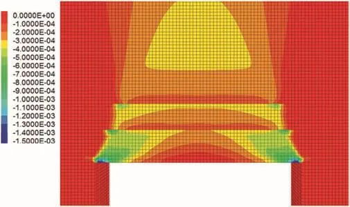
Fig. 2.Contours of compressive strain along the horizontal direction.
(2)Number of elements exceeding limits in any mode(bolted):154.
The ratio of the number of elements exceeding the critical strain values for the unbolted case to the bolted case is 1.4(=216/154)in comparison to the stability factor ratio of 1.54 for the SRT.Firstly,this minor discrepancy may be due to the fact that the SRT is a stress-based approach while CST is a strain-based one,and the stress and strain are nonlinearly related in Hoek-Brown criterion.Secondly,the successive reduction of the rock mass strength for all the layers in the SRT is unrealistic,since damage to the roof typically does not extend beyond 2 m in height.The mechanism of failure and the stress redistribution may also change due to strength reduction of the different layers.SRT is a macro-level approach that does not identify spatial initiation and propagation of failure.CST,on the other hand,is more mechanics-based approach and solves the last problem;however,it requires measurement of strains in the field to validate the selected critical strain values.The authors believe that the CST with its stronger Scientific foundations should be considered in conjunction with SRT for the design of excavations and roof supports.
3.Assessment of the effect of pre-mining stress field orientation on opening stability
Since conducting experiments in the field to identify the impact of pre-mining stress field orientation on opening is not feasible,3D continuum modeling using FLAC3Dwas utilized with field validation,where possible.Analyses were performed for a 4-way intersection with a cut-corner(typically,one corner is cut to facilitate turning of the continuous miner)in a southern Illinois mine operating in No.6 coal seam.Pre-mining stress can be an important factor in developing the extent of potentially unstable roof(Gercek,1982;Guo and Stankus,1997;Ellenberger and Miller,2012).Model generated outputs tend to be significantly different when excavation sequence is unaccounted(Sinha,2016).Hence,it was decided to consider the effect of cut sequence and orientation of pre-mining stress field while developing the improved roof control plans.
3.1.Model development
FLAC3Dwas used to perform nonlinear continuum analyses for a typical 4-way intersection in a mine in southern Illinois at a depth of 107 m.Generalized Hoek-Brown failure criterion with rock mass strength properties listed in Table 4 was used as the foundation foranalyses.The overall model was 30 m long,30 m wide and 50.1 m high.Three bedding planes at heights of 0.8 m,1.4 m and 2 m above the coal seam were included to simulate planes of weakness.The mechanical behavior of interfaces is represented in FLAC3Dby five parameters:normal stiffness,shear stiffness,cohesion,friction angle and tensile strength.Each of these values for coal measure rocks in southern Illinois were determined from laboratory testing(Bastola and Chugh,2015)and were selected for the purposes of this study(Table 5).The widths of openings in entries and crosscuts were 6 m and 5.8 m,respectively.
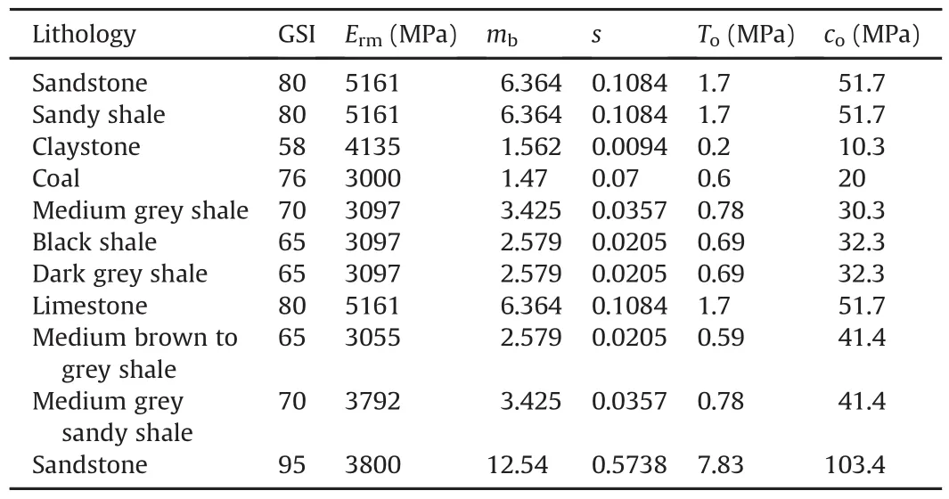
Table 4Rock mass properties used in the model.
Pre-mining horizontal stresses of 7.58 MPa and 4.13 MPa,typical in the Illinois Basin,were applied in the E-W and N-S directions.The in situ horizontal stresses were estimated from empirical equations(Mark and Gadde,2008)and a compilation of such data within the Illinois Basin(Chugh,2011).The practiced MSHA-approved roof support plan in this mine consisted of bolts placed in 1.4 m×1.4 m grid with the first bolt 0.65 m from the pillar ribs.Short encapsulation pull test(SEPT)data,provided by bolt suppliers in the region,were used to assign bolting system stiffness and strength parameters(Chugh et al.,2016).
Rock bolts in FLAC3Dare modeled as two-noded,straight pile structural elements of finite length which interact with the rock mass through a spring-slider system(Itasca,2009).Bolt suppliers provided SEPT data in the mining region for 8 tests using 1.8 m long,#6 rebar,grade 60 with the upper 0.3 m resin grouted(Sinha,2016).The elastic deformation of the un-grouted portion of the bolt was subtracted to compute an average bolt stiffness of 3.35×10⁷N/m/m.The bond strength is the load at which thegrout-rock interface starts to fail.Grip factor(GF)values in the region vary from 232 N/mm to 270 N/mm.A GF value of 270 N/mm was used that is similar to the published research(Mark et al.,2002;Ray et al.,2013).

Table 5Bedding plane interface properties used in modeling.
3.2.Effect of pre-mining stress field on intersection stability
Pre-mining horizontal principal stresses in Illinois Coal Basin are generally oriented N70°E and N20°W with typical values of 7.58 MPa(compression)and 4.13 MPa(compression),respectively.In this section,they were applied at different orientations in the horizontal plane while the vertical stress,equivalent to the depth of mining,was applied to the top of the model.In the base case(Model 1),it was assumed that entries are being driven along N-S and crosscuts along E-W to simulate north or south oriented submain or main entries.Main or sub main entries are also commonly driven along E-W and crosscuts in N-S direction.
The horizontal principal stress ratio in this region is 1:2.Where this ratio is higher or the immediate roof strata are weak,the entries are sometimes oriented at an angle to ensure that both the entries and the crosscuts are stable.Analyses have been performed for different pre-mining stress field orientations to assess intersection and mine stability.Instead of rotating the model,the in situ stress was rotated to facilitate easier modeling.The numbers in red indicate the sequence of cuts in Fig. 3.After every cut was made,bolts were installed instantaneously and the model was allowed to equilibrate.
Four models were simulated to observe the macroscopic changes caused by the rotation of the openings:
(1)Model 1 or base case(Fig. 3):Six cuts with the first two cuts of 9 m in length.The bolting pattern is similar to that discussed in Section 3.1,and the minimum compressive stress(σ3)is oriented along E-W.This is the excavation sequence followed by the mine under consideration.
(2)Model 2:This model is similar to Model 1 except that theσ3acts along the N-S direction.
(3)Model 3:Similar to Model 1 with the minimum compressive stress aligned along N60°E.
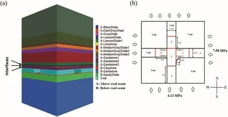
Fig. 3.(a)3D view,and(b)Map view along coal seam for Model 1.
(4)Model 4:Similar to Model 1 with the minimum compressive stress aligned along N30°E.
3.3.Results and discussions
In Model 1,the vertical displacement at the intersection center was about 16.5 mm which corresponds well with field observations(Chugh,2011).The maximum load in the bolt also matches well with field measured values of Ray et al.(2013)(see Fig. 4).The difference in the location of the maximum load is likely due to omission of the bolt bearing plate(Abbasi,2010).Fig. 5 shows that high compressive strain of about 4×10⁻³existed along the pillar ribs in the N-S entry.The compressive strains are much lower along the right side of the N-S entry than that on the left side.This is because Cuts 3 and 5 relieved some of the stress before Cut 6 was made.High positive shear strains existed around the turned corner.The deformed mesh(exaggerated)of the first element in the roof,as shown in Fig. 6a,indicates that there is some distortion near Corner 2.Additionally,there is a high curvature roof deformation near Corner 3.Both of these are manifested as high compressive strains.In terms of failed zone(Fig. 6b),shear failure was observed in pillar ribs along E-W direction while the corners failed due to a combination of tension and shear.

Fig. 4.Distance from bolt head versus axial load in N-S entry and intersection:Comparison of model and field data(after Ray et al.,2013).
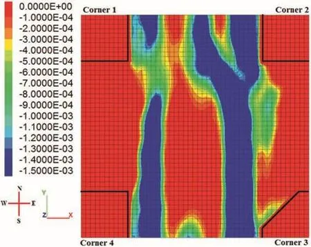
Fig. 5.Contour of compressive strains in X-direction in the roof.
A plot of shear and compressive strains after each cut revealed that high shear strains developed only after Cut 3 was made and increased with Cuts 4 and 5.On the other hand,the distortion near Corner 3 occurred only when Cut 5 was made.Prior to Cut 6,the left portion of the E-W crosscut was solid coal and had higher stiffness,reducing the relative freedom of the rock mass to deform.Once Cut 5 was made,the roof relaxed near Corner 2 and caused the distortion.Consequently,the load in the bolt around that area increased to 142 kN.
In Model 2,high compressive strain was localized in the E-W direction.Although there was a 6%decrease in the area of critical compressive strain zone as compared to Model 1,critical shear zones increased by 48%.The magnitude of peak shear strain also increased to 2.1×10⁻³.High shear strains around Corner 3 may cause distortion and ultimately lead to failure.A review of the strains development after each cut revealed that Corners 3 and 4 were subjected to high shear strains after Cuts 3 and 6.Although the compressive strains can be reduced slightly by reorienting the direction of cut sequence with respect to the minimum compressive stress,it increased the shear strains significantly.It suggests that reorienting the cut sequence in relation to the minimum compressive stress direction may help to stabilize the intersection for higher ratios of the two horizontal pre-mining compressive stresses.
In Model 3,the minimum principal stress was aligned along N60°E.This was done by assigning normal stresses on the N-S and E-W faces of the model with appropriate shear stresses in the horizontal plane.A large reduction in the area of critical compressive strains was seen along the left side of the entry in comparison to Model 1.The stiffer rock mass along the left portion of the E-W crosscut reduced additional deformations with lower compressive strains.There was a large increase in positive shear strain along the turned corner(Corner 3).This may have been caused by the angular orientation of the pre-mining stress field which amplified the shear strains along the turned corner.Negative shear strains at Corners 2 and 4 were also found to increase marginally.
Finally,in Model 4,the minimum principal stress was aligned along N30°E.The compressive strains alongX-andY-directions(Fig. 7)were much smaller than those in Model 1 although there was a zone of high compression along the turned corner.High positive shear strains also existed around the turned corner(Fig. 8).Entry orientation with respect to pre-mining stress field minimized compressive strains to a large extent,but incurred additional shear strains at corners.High shear strains can result in failure of corners,which can increase the intersection roof span.Appropriate support systems must be designed to control rock mass failure around this turned corner.
In order to quantify the extent of instability around the intersection for the four different models,the number of elements exceeding critical tensile,compressive and shear strains within 1.8 m(bolting horizon)of the immediate roof and over an area of the intersection plus 2 m was counted and is shown in Table 6.Each element in the bolted horizon has uniform dimensions of 0.2 m×0.2 m×0.1 m.Thus,the overall volume of rock mass susceptible to failure initiation can be computed.For simplicity,only number of elements is reported in Table 6.
The normal(compressive and tensile)strains are distributed alongX-andY-directions when σ3was oriented along N30°E and N60°E.This may improve intersection stability since the critical normal strains are distributed over a larger area.From that perspective,N30°E and N60°E orientations seems more stable than NS and EW orientations.A closer look at the critical normal strain areas for N30°E and N60°E cases revealed that N30°E orientation is more stable.From critical shear strains point of view,EW case is the most stable.Since a particular orientation could not be identified as the best,additional analyses were performed to simultaneously account for normal and shear strains.Since an element can fail in more than one mode,elements which have failed in any one mode(either shear or tensile)were counted(Table 7).In Table 6,it was not possible to add the number of elements since there would be an overestimation due to repeated counting of a single element failing in multiple modes.

Fig. 6.(a)Deformed mesh of the immediate roof,and(b)Yielded elements in the floor and the pillar around Corner 2.
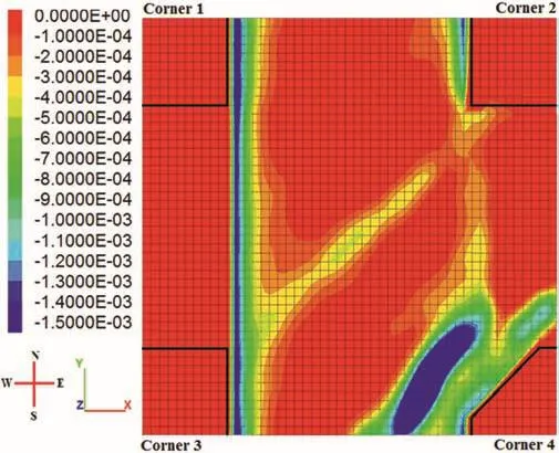
Fig. 7.Contour of compressive strain in X-direction.

Fig. 8.Contours of shear strains around the intersection.

Table 6Number of elements exceeding critical strain within the bolting horizon based on varying the pre-mining stress field.
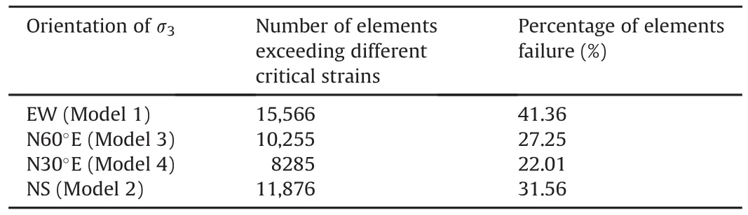
Table 7Number of elements exceeding the critical strain within the bolting horizon in any mode,encompassing the intersection and 2 m around it(37,632 elements).
Results in Table 7 do not correspond with Gadde(2003)who concluded N45°E to be the most unstable orientation with EW or NS as the best.The conclusions were based on averaging the factor of safety for models with five different principal stress ratios in the immediate roof.It is also possible that the difference is due to localized stress and strain distributions caused by the cut sequence.To investigate the reason for the discrepancy in the obtained results,additional cases were simulated where all the cuts were excavated instantaneously.These results corroborated well with US National Institute for Occupational Safety and Health(NIOSH)’s Analysis of Horizontal Stresses in Mining(AHSM)software and Gadde(2003),thus attributing the discrepancy to cut-sequence.The reader can refer to Sinha(2016)for further details on this study.
4.Alternate roof control plans

Fig. 9.Deformed mesh of immediate roof around an intersection.
It was found in the previous section that orienting the entry at 30°to the direction of the minimum principal stress(Model 4)and excavating the first two cuts in 9 m length provided the maximum stability to the intersection.This section further attempts to reduce the critical strain areas through strategic installation of roof supports.Figs.8 and 9 depict the critical shear strain areas and exaggerated deformed mesh in the immediate roof whenσ3is oriented along N30°E.Corners 1 and 3 are subjected to high positive shear strains.Such high strains are likely to cause distortional failures of the corners that will increase the exposed roof span of the intersection.Since normal strains are low in this model(refer Fig. 7),it was decided to only reduce shear strains around corners.Pre-tensioned and inclined bolts were installed around areas of high critical strain to assess their effect on elements exceeding critical strain limits within the bolted horizon.
4.1.Alternate roof control plan#1
In this layout(Fig. 10),three 1.8 m long,#8 rebar bolts were installed vertically at each of the four intersection corners.These bolts were located 0.5 m from the pillar edge and the spacing between bolts was 1.5 m.The pre-tension loads of 50 kN and 100 kN were applied to all 12 bolts.Because these pre-tension loads did not reduce the volume of critical rock mass significantly(<10%),the load was increased to 150 kN to stiffen the corners.The corner bolt at the turned corner assumed the maximum load of 228 kN during the course of simulation,thus,a#8 rebar was selected.Results showed a significant reduction in shear strains,especially around Corners 1 and 3.
4.2.Alternate roof control plan#2
This layout followed the previous bolting pattern except that all 12 bolts were inclined at 45°towards the solid coal pillar.Some minor angle adjustments were made to prevent bolts from crossing each other.A pre-tension load of 100 kN was applied to these inclined bolts.There was a notable decrease in positive as well as negative shear strains at all four corners(Fig. 11).In addition,there was a 37.4%reduction in normal strains in theY-direction compared to Model 4 of previous section.
4.3.Alternate roof control plan#3
In this case,the pre-tension load in all 45°inclined bolts was increased to 150 kN.From plots of deformed mesh(Fig. 12)and shear strain(Fig. 13),it can be concluded that the critical areas of instability have been reduced substantially.
4.4.Analysis of number of elements exceeding the critical strain value
Table 8 lists the number of elements the exceeding critical strains with the following observations:
(1)Inclined bolts resulted in substantial decrease in critical strains.This is due to the application of a resistive force normal to the deformation tendency of intersection corners.Since a bolt performs better in tension than in shear,identifying such orientations is crucial to the overall efficiency of a bolting plan.
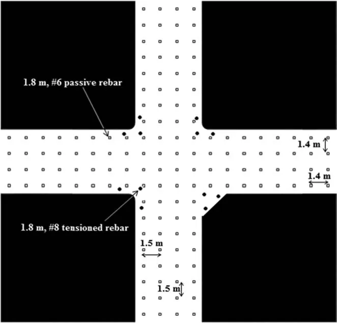
Fig. 10.Plan#1 for improved support around an intersection.

Fig. 11.Contours of shear strain around an intersection with Plan#2 for alternate roof control.
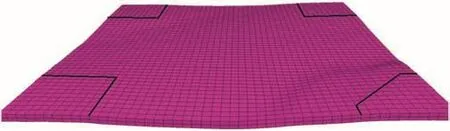
Fig. 12.Deformed mesh of the immediate roof with Plan#3 for alternate roof control.

Fig. 13.Contour of shear strain around the intersection with Plan#3.
(2)Alternate bolting plan#3 reduced the critical shear strain by 79.3%as compared to Model 4 in the previous section.It also reduced the critical compressive and tensile strains inY-direction by 64.08%and 41%,respectively.
(3)To better understand the effect of the inclined bolts,additional analyses were conducted to count the elements exceeding any critical strain(i.e.compressive,tensile orshear).This combined the improvement in critical normal and shear strain areas and represented it using a composite value.Table 9 shows the number and percentage of elements failing in any mode.

Table 8Number of elements exceeding the critical strain within the bolting horizon for alternate roof control plans.

Table 9Number of elements exceeding the critical strain within the bolting horizon in any mode with alternate roof control plans,encompassing the intersection and 2 m around it(37,632 elements).
(4)Alternate proposed roof control plans#1,#2 and#3 reduced the overall critical area by 37%,51.9%and 70.8%,respectively.It may seem that on further increasing the bolt pre-tension,the critical strain areas would reduce leading to a more stable intersection.However,it must be realized that there is an industrial limitation to the amount of pre-tension that can be applied to a bolt.Additionally,there is a cost associated with higher pre-tension and thicker bolts.Whether 150-kN pretension can be realistically applied with a precise bolt inclination is not the essence of this study.The goal is to demonstrate that such a methodology could be followed to design a more effective roof control plans.
5.Conclusions
This research has performed a 3D numerical analysis of strain distribution around a typical 4-way coal mine intersection in the Illinois Coal Basin.The goal of the study was to develop improved roof support layouts through identification of critical areas around the intersection.Since researchers have faced problems in the past in assessing the effectiveness of support systems,an alternative approach is discussed here to assess the areal reinforcement through continuum analyses of yielded zones and strain-based criteria of failure of rock mass in each zone.This approach computes three separate reinforcement factors:RFT,RFC and RFSS.
It was found that damage nucleates around intersection corners in shear mode.The distortion caused byshear strain often results in corner spalling that can in turn increase the exposed roof span.In regions where the two horizontal stresses are significantly different,compressive strains can localize along the entries and manifest as cutter roof.The high compressive strains can also increase the load in bolts causing localized roof failures.
A sound Scientific analysis is imperative to the design of roof control plans.Oftentimes,some designs are based on experience rather than an understanding of the potential failure mechanisms.A deeper insight into the critical areas can help in determining the location as well as the support capacity that is necessary for stabilization.Furthermore,the relative efficiency of different support types as a function of loading direction must be understood and utilized in this regard.
This study has shown that a sequential approach,starting with modification of the entry direction with respect to pre-mining stress field,followed by Scientific positioning of secondary supports,can prove to be extremely effective in minimizing the unstable areas around an intersection.A similar methodology should be followed when designing roof control plans for coal mines.With the advent of CST,it becomes easier to assess and compare the reinforcement effect of different roof control plans over user defined regions.A major advantage is the ability to determine whether a particular support(suited for certain loading type)is effective in reinforcing the target region/volume.Currently,endeavors are being made to use this approach in design of rib supports.
Conflict of interest
The authors wish to confirm that there are no known Conflicts of interest associated with this publication and there has been no significant financial support for this work that could have influenced its outcome.
Abbasi B.A numerical analysis of mine intersections and support systems for stability.Carbondale,IL:Mining and Mineral Resources Engineering,Southern Illinois University;2010.MS thesis.
Baker M.Architectural measures to minimize subsidence damage.Appalachian Regional Commission(ARC)Report 73-111-2551.ARC;1974.
Bastola S,Chugh YP.Shear strength and stiffness properties of bedding planes and discontinuities in the immediate roof rocks overlying the No.6 coal seam in Illinois.In:Proceedings of international society for rock mechanics(ISRM)2015.Montreal,Canada:ISRM;2015.
Chugh YP.Geological and geotechnical evaluation of the first quadrant reserve of White Oak Resources.Final Report.McLeansboro,IL:White Oak Resources;2011.
Chugh YP,Kollipara V.An analysis of roof fall database for Illinois coal mines.In:Illinois clean coal Institute(ICCI)annual meeting.ICCI;2009.
Chugh YP,Sinha S.Numerical modeling of roof support plans at 4-way coal mine intersections.In:Proceedings of the 49th US rock mechanics/geomechanics symposium.American Rock Mechanics Association(ARMA);2015.
Chugh YP,Sinha S,Tinsley J,Gurley H.An analysis of short encapsulation bolt pull test(SEPT)data from interior basin coal mines.In:Proceedings of the 2nd specialty conference on soft rock;2016.
Ellenberger J,Miller T.Mitigating the effects of high horizontal stress on ground control in an underground stone mine:a case history.In:Proceedings of the 31st international conference on ground control in mining;2012.
Esterhuizen GS.A stability factor for supported mine entries based on numerical model analysis.In:Proceedings of the 31st international conference on ground control in mining;2012.
Gadde MM.Effect of in-situ stresses on the stability of coal mine development workings.Morgantown,WV:West Virginia University;2003.MS thesis.
Gale WJ,Mark C,Oyler DC,Chen J.Computer simulation of ground behavior and rock bolt interaction at emerald mine.In:Proceedings of the 23rd international conference on ground control in mining.Morgantown,WV:West Virginia University;2004.p.27-34.
Gercek H.Stability of intersections in room and pillar coal mining.University Park,PA:Pennsylvania State University;1982.Ph.D.thesis.
Guo S,Stankus JC.Control mechanism of a tensioned bolt system in the laminated roof with a large horizontal stress.In:Proceedings of the 16th conference on ground control in mining;1997.
Hanna K,Conover D.Design of coal mine entry intersection.Pittsburgh,PA:US Department of the Interior;1988.
Hanna K,Conover D,Haramy K,Kneisley R.Structural stability of coal mine entry intersection-case studies.In:Proceedings of the 7th US symposium on rock mechanics;1986.p.512-9[Chapter 74].
Itasca.FLAC3D-fast Langrangian analysis of continua in 3-dimension.4th ed.Minneapolis,MN:Itasca Consulting Group,Inc.;2009.
Marinos P,Hoek E.GSI-a geologically friendly tool for rock mass strength estimation.In:Proceedings of geo eng 2000;2000.p.1422-42.
Mark C,Gadde MM.Global trends in coal mine horizontal stress measurements.In:Proceedings of the 27th international conference on ground control in mining.Morgantown,WV:West Virginia University;2008.p.319-31.
Mark C,Compton C,Oyler D,Dolinar D.Anchorage pull testing for fully grouted roof bolts.In:Proceedings of the 21st international conference on ground control in mining.Morgantown,WV:West Virginia University;2002.p.105-13.
Ray AK,Gadde MM,Spearing AJS.Numerical modeling of the performance of active and passive bolts installed at an Illinois Basin coal mine.In:Proceedings of the 47th U.S.Rock mechanics/geomechanics symposium.ARMA;2013.
SinhaS.Analysis for design and support of coal mine intersection.Carbondale,IL:Mining and Mineral Resources Engineering,Southern Illinois University;2016.MS thesis.
Sinha S,Chugh YP.An evaluation of roof support plans at two coal mines in Illinois using numerical models.International Journal of Rock Mechanics and Mining Sciences 2015;82:1-9.
Spearing AJS,Mueller A.Intersection support in US coal mines.Final Report.The National Institute for Occupational Safety and Health(NIOSH);2008.Contract No.254-2008-M-24358.
 Journal of Rock Mechanics and Geotechnical Engineering2018年2期
- Journal of Rock Mechanics and Geotechnical Engineering的其它文章
- A new design equation for drained stability of conical slopes in cohesive-frictional soils
- Resilient modulus prediction of soft low-plasticity Piedmont residual soil using dynamic cone penetrometer
- Assessment of natural frequency of installed offshore wind turbines using nonlinear finite element model considering soil-monopile interaction
- Behavior of ring footing resting on reinforced sand subjected to eccentric-inclined loading
- Investigation of active vibration drilling using acoustic emission and cutting size analysis
- Numerical analysis of Shiobara hydro power cavern using practical equivalent approach