Axisymmetric alternating direction explicit scheme for efficient coupled simulation of hydro-mechanical interaction in geotechnical engineering-Application to circular footing and deep tunnel in saturated ground
Simon Heru Prssetyo,Mrte Gutierrez
aDepartment of Civil and Environmental Engineering,Colorado School of Mines,Golden,USA
bMining Engineering Program,Institut Teknologi Bandung,Bandung,Indonesia
1.Introduction
Biot’s theory of poroelasticity(Biot,1941)has gained new prominence in geotechnical engineering to understand the coupled response of fluid f l owand deformation in deformable porous media(i.e.soils and rocks).The most common examples of this coupled hydro-mechanical(H-M)interaction are consolidation and subsidence induced by fluid extraction from underground formations(e.g.oil and gas from hydrocarbon reservoirs and water from aquifers).In these examples,the transient fluid f l ow affects deformation in the ground and vice versa(Wang,2000;Gutierrez and Lewis,2002;Neuzil,2003).Thus,consideration of this H-M interaction is essential for the safe design of structures built above or in saturated ground such as circular footing and deep tunnel.
Among various techniques to solve the coupled H-M equations,explicit technique is the most attractive one to be used(Minkoff et al.,2003;Dean et al.,2006).The technique not only is simple to be implemented,but also requires less time in building the separate mechanical and fluid f l ow codes for solving the coupled Biot’s equations that govern the response of the fluid and the porous medium.Unfortunately,explicit techniques come at a price:they are only conditionally stable.The nature of an explicit technique requires that small time step sizes must be used to maintain numerical stability,placing a strong limitation on the technique.Consequently,the efficiency of computer runtime for an explicit-type coupling approach cannot be fully exploited for largescale and long-term H-M simulations that may need enormously long computation time.For example,the H-M response of tunneling in low-permeability ground may need a consolidation time up to 250 years to reach the steady-state pore pressure distribution(Prassetyo and Gutierrez,2016a,b).
One of the most widely used explicit finite difference(FD)codes for H-M simulation in geotechnical engineering is the fast Lagrangian analysis of continua(FLAC)developed by Itasca(2011a).It is also conditionally stable.The time step size used for its f l ow calculation must be lower than a critical value in order that the pore pressure behavior remains stable and monotonic(Itasca,2011b).Unlike the fluid f l ow effect that takes place over a considerable amount of time,the geomechanical calculation in FLAC is not of particular concern because the response occurs almostinstantaneously particularly forstaticgeomechanical problems.
2.Need for an efficient explicit coupling technique
To improve the efficiency of an explicit coupling technique,one proposed method is to use an unconditionally stable fluid f l ow scheme that can be sequentially coupled with an existing geomechanical simulator such as FLAC.The alternating direction explicit(ADE)is one of such schemes.In an ADE scheme,two explicit FD equations are executed simultaneously in two physical directions:one in a forward sweep and the other in a reverse sweep(see Fig. 1).
To obtain the mathematical sense of how the ADE scheme works,the following diffusion equation is considered:

wherepis the pore pressure.
As presented in Barakat and Clark(1966),to solve Eq.(1),the ADE scheme executes two explicit FD equations in a forward sweep(Eq.(2))and in a reverse sweep(Eq.(3)):

Fig. 1.Illustration of(a)the forward and(b)the reverse sweeps of the standard plane strain ADE scheme.

wherea,bandcare the constants defined as

The final solution is the average of the solutions from the two sweeps defined as

It can be seen from Eqs.(2)and(3)and Fig. 1 that to solve a target point(xi,yj)at the current time level(n+1),both sweeping procedures use a combination of the solutions from the previous time level(n)and the current time level(n+1).The difference,however,is indicated by the location of the solutions from the current time level(n+1)with respect to the location of the target point.In the forward sweep(Eq.(2)),the calculation marches upward in an ascending order ofxandyin which the solutions from the current time level(n+1)are located behind the target point(Fig. 1a).On the other hand,in the reverse sweep(Eq.(3)),the calculation marches downward in a descending order ofxandyin which the solutions from the current time level(n+1)are located ahead of the target point(Fig. 1b).In this way,the explicitness of the scheme is preserved while improving the stability of the scheme.This is the merit of an ADE scheme.
Despite its unconditional stability,the standard ADE scheme has three major drawbacks.First,it is only a second-order accurate scheme in time and space.This low-order accuracy will result in low numerical accuracy when a large time step size is used.Second,it is only valid for uniform grid sizes with the sameΔxandΔyfor the entire grid model.This limitation prevents the standard ADE scheme from solving large-scale f l ow problems with increasing grid size towards the far-field boundaries.Third,it is only valid for plane strain conditions.This means that it cannot be used for solving f l ow problems under axisymmetric conditions.
The main objective of this paper is to remedy the drawbacks of the standard ADE scheme so that the new ADE scheme can be coupled with a geomechanical simulator for an efficient simulation of axisymmetric coupled H-M problems in non-uniform grids.This will be achieved by formulating a novel high-order ADE scheme capable of solving the axisymmetric fluid f l ow problem in non-uniform grids.Derivation of the new scheme will be done by performing a fourth-order FD approximation of the spatial of the derivatives axisymmetric fluid-diffusion equation in a nonuniform grid configuration.The resulting fluid f l ow solution is then sequentially coupled with the existing geomechanical simulator in FLAC.Because the time step restriction is now removed,the H-M simulation can now be performed efficiently with less computation time while still maintaining numerical stability and high numerical accuracy.This paper is a major extension of the newly-derived high-order ADE scheme for solving plane strain fl ow problem in non-uniform grids(Prassetyo and Gutierrez,2017a,b).
3.Governing equations for a coupled H-M problem
According to Biot’s theory of poroelasticity(Biot,1941),the coupled equations governing the responses of the fluid(pore pressure)and the solid(effective stress)are related to the changes in fluid content(ζ)and volumetric strain(εvol)of the porous medium.This relation can be written as

whereMis the Biot modulus;α is the Biot coefficient;σijis the total stress tensor;δijis the Kronecker delta tensor;andKandGare the drained bulk and shear moduli of the porous medium,respectively.The change in fluid content can be related to the change in pore pressure bysubstituting Darcy’s law in Eq.(8)into the mass balance equation in Eq.(9).After neglecting the gravitational term,the resulting relation is given in Eq.(10).

wherekis the mobility coefficient(k=kH/γw),kHis the hydraulic conductivity,γwis the unit weight of fluid,ρwis the fluid density,and g is the gravitational acceleration vector.
In this paper,the contribution from the mechanical deformation to the incrementof pore pressureis evaluated in the geomechanical calculation.Thus,during the f l ow calculation, δεvol=0.By substituting Eq.(10)into Eq.(6),the transient response of the fluid is then governed by the Laplacian of the pore pressure as

wherecvis the fluid diffusivity defined ascv=kM.
Eq.(11)is the partial differential equation(PDE)of the f l ow problem for a plane strain condition(i.e.for a coordinate system adopted in PlaneAin Fig. 2).For an axisymmetric condition,the PDE in Eq.(11)may be rewritten in the form of Eq.(12),which corresponds to the adopted coordinate system shown in PlaneBin Fig. 2:
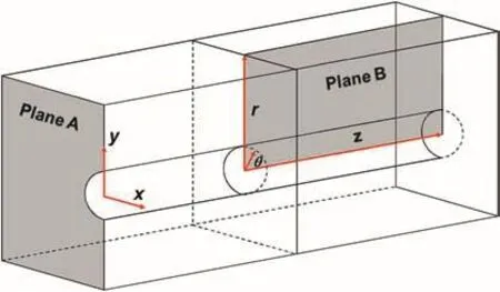
Fig. 2.Illustration of the coordinate systems used for plane strain(Plane A)and axisymmetric(Plane B)analyses.

wheref= ∂p/∂t,the variableris in the radial direction,whilezis in the axial direction.The pore pressurepin Eq.(12)is assumed to be independent in the angularθdirection.
4.Novel high-order axisymmetric ADE scheme
4.1.Development of high-order axisymmetric ADE scheme
Todeveloptheproposedhigh-orderaxisymmetricADE scheme for a non-uniform grid,the non-uniform FD approximations of the axisymmetric diffusion equation in Eq.(12)must be developed first.To do this,we consider a general non-uniform FD grid that consists of four quadrilateral elements in the axisymmetric coordinate system in Fig. 3.From Fig. 3,writing the Taylor series expansion forpi+1,jandpi-1,jto the fourth-order gives

Multiplyingpi+1,jin Eq.(13)by Δr-andpi-1,jin Eq.(14)by Δr+,and disregarding the remainder terms gives
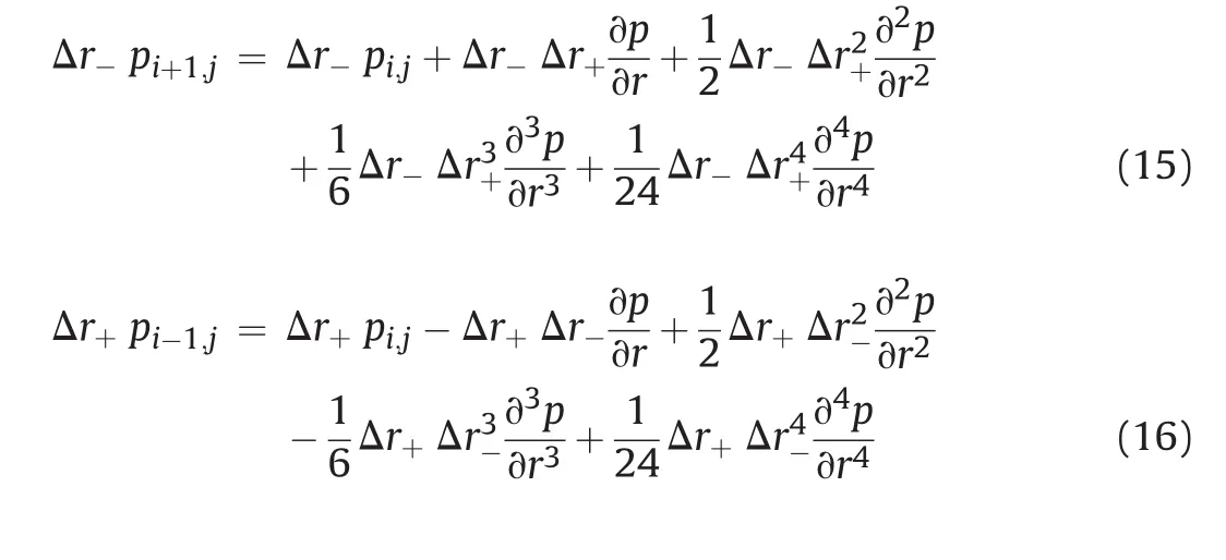
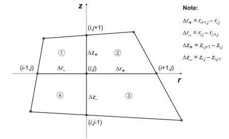
Fig. 3.Non-uniform FD grid for the axisymmetric coordinate system.
To obtain ∂p/∂r,Eq.(14)is subtracted from Eq.(13);while to obtain ∂2p/∂r2,Eq.(16)is added to Eq.(15).To obtain ∂2p/∂z2,the steps to get Eqs.(13)-(16)are repeated forzand the resulting equations are added.These operations give


Therefore,solving Eqs.(17)-(19)for∂p/∂r,∂2p/∂r2,and ∂2p/∂z2,respectively,gives


In order to have the desired fourth-order approximations for∂p/∂r,∂2p/∂r2,and ∂2p/∂z2,the higher-order partial derivatives∂3p/∂r3,∂4p/∂r4,∂3p/∂z3,and ∂4p/∂z4in Eqs.(20)-(22)need to be approximated to the second-order accurate ones.To accomplish this,we perform repeated differentiations of Eq.(12)with respect torandzuntil the higher-order terms appear.The differentiations give


The next step is to use the centered difference approximations in Eq.(23)for the lower-order partial derivatives in Eqs.(24)-(27)and substitute those approximations into Eqs.(20)-(22)and the governing equation in Eq.(12).By performing this operation,the desired fourth-order FD approximations of the axisymmetric diffusion equation can be obtained as

where
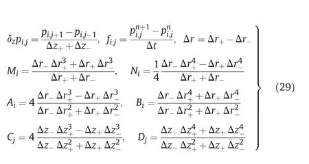
To assemble the fourth-order approximation of the axisymmetric ADE scheme,the well-known Crank-Nicolson implicit time integration scheme(Crank and Nicolson,1947)is applied to Eq.(28).The principle of the Crank-Nicolson technique is that difference approximations are developed at the midpoint of the time incrementn(Chapra and Canale,2009).To do this,the temporal derivative ∂p/∂tis approximated attn+1/2as

while the spatial derivatives ∂2p/∂r2and ∂2p/∂z2can be approximated at the midpoint by averaging the spatial derivatives at the beginningtnand at the endtn+1of the time increment as

Finally,having performed the operation,the novel high-order axisymmetric ADE scheme for a non-uniform grid can be written for the forward sweep as


and for the reverse sweep as whereα0toα8and β1to β4are the grid size-dependent constants.The expressions for these constants are given in Eqs.(A1)-(A5)in the Appendix to prevent encumbering the mainpresentation in the text.These constants are made up of more terms than those in Eq.(4)to account for non-uniformity in grid size.Fig. 4 illustrates the arrangement of the calculation sweeps for the newly-derived highorder axisymmetric ADE scheme.Compared to the standard scheme in Fig. 1,the new ADE scheme involves more contributing points in the calculation of the target point because of the fourthorder approximation,e.g.additional diagonal points from the cross-derivatives.Nevertheless,the new scheme still maintains the nine-point stencil,preserving its compactness.
The axisymmetric ADE scheme in Eqs.(33)and(34)is valid for all points inside the FD grid except for the points along the axis of symmetry or atr=0(see Fig. 5).The PDE in Eq.(12)has a singularity atr=0 because the equation encounters a division of 0/0 for the (1/r)∂p/∂rterm.To remove this singularity,L’Hospital’s rule must be used.The numerator and the denominator of the term(1/r)∂p/∂rmust be successively differentiated with respect toruntil a finite limit is achieved.Eq.(35)shows the operation of L’Hospital’s rule for the (1/r)∂p/∂rterm,in which the term simply becomes ∂2p/∂r2:

After substituting ∂2p/∂r2for (1/r)∂p/∂rin Eq.(12),the PDE becomes that shown in Eq.(36).This is the governing PDE that needs tobe discretized toobtain the high-order ADE scheme for the boundary points located along the axis of symmetry(called the axisymmetric boundary points from now on).

For the axisymmetric boundary points,the steps to develop the corresponding high-order axisymmetric ADE scheme are the same as those for the interior points.The steps will not be repeated here but the final arrangements will be given.
Having performed the operation presented in Eqs.(13)-(34),the novel high-order axisymmetric ADE scheme for the axisymmetric boundary points can be written for the forward sweep as

Note that the constants α1,α5,α7,and β1are now equal to zero,meaning that fewer neighboring points are needed in the calculation.The expressions for grid size-dependent constants for the axisymmetric boundary points are given in Eq.(A6)in the Appendix.
Note that in the above derivations,the mobility coefficientk=kH/γwhas been assumed to be constant,causing the fluid diffusivitycvin the grid size-dependent constants to be constant as well.The permeability of a porous medium can certainly be made anisotropic by having different mobility coefficients in the radial and axial directions(krandkz,respectively).To accommodate this anisotropy,Eqs.(12)and(36)can be rewritten in more general forms as
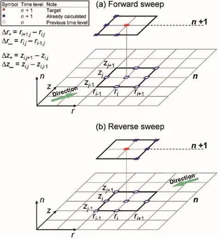
Fig. 4.Illustration of(a)the forward and(b)the reverse sweeps of the new high-order axisymmetric ADE scheme.

4.2.Proof of convergence
Convergence is the attribute that the newly-derived ADE scheme must have to instill conf i dence in its results.According to the Lax-Richtmyer equivalence theorem,stability and consistency are the conditions to be satisf i ed by an FD scheme in order for it to be called a convergent scheme(Richtmyer and Morton,1967).Stability means that errors at any stage of the computation decay as the computation progresses,while consistency means that the FD scheme reduces to the governing PDE as the increments in the independent variables vanish.
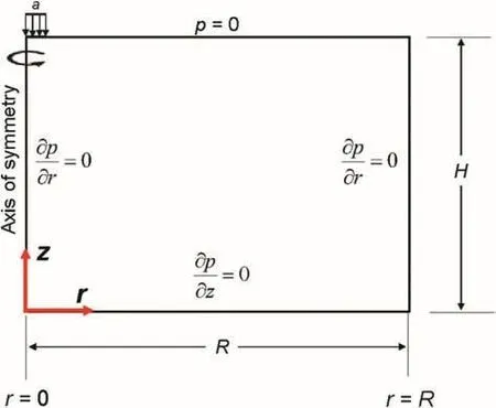
Fig. 5.Illustration of an axisymmetric consolidation showing location of the axis of symmetry.
4.2.1.Stability
To prove the stability of the new ADE scheme,the von Neumann stability analysis is used.The new ADE scheme can be said to be stable if the amplif i cation factor of the solution meets the criterion|G(θ)| 1 when the solution is advanced one time step,expressing the decay of the frequency amplitude of the solution(Barakat and Clark,1966;Hoffman,2001;Strikwerda,2004;Mazumder,2016).To use the von Neumann stability analysis,the pore pressure solutions to the forward and reverse sweeps are rewritten in separable Fourier expansions as

For the interior points,the substitution yields the expression for calculatingG(θ)for the forward sweep as

and for the reverse sweep as

Likewise,for the axisymmetric boundary points,the substitution yields the expressions for calculatingG(θ)for the forward sweep as

and for the reverse sweep as

To check if the criterion for stability is met for each sweep,i.e.|G(θ)| 1,graphical examination ofG(θ)will be helpful.To do this,the material properties from the axisymmetric consolidation problem in Section 5 are used to calculate the grid size-dependent constants from Eqs.(A1)-(A6).The resulting values of the constants are substituted into Eqs.(42)-(45)and the resulting values ofG(θ)with varying θare then plotted.Fig. 6 shows the plots ofG(θ)for the forward and reverse sweeps for the interior points(Fig. 6a)and for the axisymmetric boundary points(Fig. 6b).It can be seen that as θvaries,the set of points marked out byG(θ)lies within the unit circle with the radius of unity,ensuring that the FD solutions are bounded and that the new ADE scheme is unconditionally stable.In either interior or axisymmetric boundary points,the shape of theG(θ)curve for each sweep is not the same because the equations forG(θ)for each sweep are also different,resulting in different values of grid-size dependent constants.
4.2.2.Consistency
The consistency condition requires that the truncation errors of the newly-derived ADE scheme vanish asΔr,Δz,and Δtapproach zero.The behavior of the truncation errors for the interior grids can be investigated by looking at Eq.(28)because the discretization of the high-order axisymmetric ADE scheme comes from this equation.Eq.(28)may be rewritten as

where τi,jis the truncation error resulting from expanding the governing equation in Eq.(12)to the fourth-order one.The truncation error is defined as
Assuming that uniform grid sizes are used,Δr_= Δr+= Δrand Δz_= Δz+= Δz,the constantsM,N,A,B,C,andDdefined in Eq.(29)becomeΔr3,0,0,Δr2,0 and Δz2,respectively.Clearly,when these grid sizes approach zero, τi,jwill be zero and Eq.(46)reduces to the governing PDE defined in Eq.(12),guaranteeing the consistency of the new scheme.A similar approach can be taken for the axisymmetric boundary points in which when the truncation error goes to zero,the governing PDE in Eq.(36)will be recovered.
4.3.efficient sequential coupling technique
The coupled problems in this paper will be modeled and solved in FLAC.At every time step,the newly-derived axisymmetric ADE scheme will first be executed to solve the fluid f l ow problem,and then the system will be sequentially brought to geomechanical equilibrium using FLAC’s built-in geomechanical simulator.From now on,the use of the axisymmetric ADE scheme in FLAC is called the sequentially-explicit coupling technique based on the fourthorder axisymmetric ADE scheme or SEA-4-AXI.This coupling technique is written in FLAC’s programming language called FISH(Itasca,2011c).Fig. 7 shows the f l owchart of SEA-4-AXI to solve the coupled problems in this paper.
From the state of geomechanical equilibrium,the solution to a coupled H-M problem is obtained sequentially by fi rst solving the fl ow problem and then the geomechanical problem.The new fourth-order axisymmetric ADE scheme is called to solve fl ow problem,resulting in the pore pressure solutionpn+1.Note that the increment of pore pressure due to volumetric strain is evaluated in the geomechanical calculation as a zone value which is then distributed to the grid points.The total stress correction due to this pore pressure change is then calculated and updated into the geomechanical calculation.At the end of this geomechanical step,the displacement solutionun+1is obtained.Several geomechanical steps may be taken to bring the system to equilibrium before the computation progresses to the next time step.This sequential procedure is repeated until the desired simulation time is reached.
It is worth mentioning that the geomechanical calculation in FLAC invokes the equations of motion to derive new velocities and displacements from stresses and forces.Strain rates are then derived from velocities,and new effective stresses from strain rates according to the adopted constitutive law.If the water bulk modulus is given,new increments of pore pressure due to pore volume change will also be evaluated from strain rates.This increment is called the mechanical generation of pore pressure.This cycle constitutes one geomechanical step.At the beginning of an H-M simulation,one fluid time step may putthesystem considerablyoutofequilibrium,inducing large unbalanced forces in the model.At this stage,many geomechanical steps will be taken for each fluid step.As the consolidation process continues,the changes in fluid pressure will become small,so that the system will remain in equilibrium(Itasca,2011b).

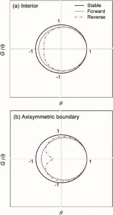
Fig. 6.Variation of G(θ)for the forward and reverse sweeps of the new axisymmetric ADE scheme for(a)the interior and(b)the axisymmetric boundary points.
In this paper,the accuracy and efficiency of SEA-4-AXI will be compared to FLAC’s built-in coupled technique called the basic scheme.The basic scheme uses the explicit f l ow formulation which requires that the fluid time step size should be smaller than a critical valueΔtcri.The value is calculated internally based on a discretization of the medium into zones composed of two overlaid triangular elements,in which the nodal fluid f l uxqis solved by using the Gauss divergence theorem(Itasca,2011b).The merit of SEA-4-AXI is that it removes this time step restriction,leading the explicit coupling technique to yield an efficient H-M simulation without suffering from numerical instability yet still maintaining high numerical accuracy.

Fig. 7.The sequential coupling technique in FLAC using the fourth-order axisymmetric ADE scheme(SEA-4-AXI).
5.Axisymmetric consolidation of a circular footing

Fig. 8.Geometry and non-uniform FD grid of the axisymmetric consolidation beneath a circular footing.

Table 1Material properties for McNamee’s problem.
SEA-4-AXI is first validated to simulate the H-M response of an axisymmetric consolidation of a circular footing known as McNamee’s consolidation(McNamee and Gibson,1960),which is a commonproblem in geotechnicalengineering.A fullysaturated soil layer of heightH=30 m and widthW=40 m is loaded by a constant uniform pressure ofpo=100 kPa over a circular area of radiusa=2 m.The soil is free to drain at the surface but the other boundaries are impermeable.The FD grid is gradually increasing in size toward the right and bottom boundaries of the model,testing the validity of the non-uniform FD approximation in the new axisymmetric ADE scheme(Fig. 8).The material properties for the model are given in Table 1.The model is run to a consolidation time oft=250 years,which is about 112 times the normalized consolidation timet*for this problem(t*=cvt/a2).The simulation in SEA-4-AXI uses Δt=20 d,while that in FLAC’s basic f l ow scheme uses Δtcri=5 d.
Note that the paper adopts the sign convention used in rock mechanics that stress and displacement are positive for compression.Unless stated otherwise,all pore pressures are total(initial hydrostatic plus excess pore pressure)and all stresses are effective.Further,the H-M simulations performed in this paper use constant Biot’s coefficientα =1,and the coefficient does not change with the mechanical deformation.This is done to justify the two simplif i ed assumptionsin thispaper:theground iselasticand the compressibility of grains is neglected compared to that of the drained bulk modulusK.The effects of usingα 1 and of varyingα with deformation on the H-M response of consolidation problems can be seen in the study of tunneling in poroplastic medium done by Bobet(2010).

Fig. 9.Contours of(a)pore pressure,(b)effective vertical stress,and(c)radial displacement after 25 years of consolidation(comparison between SEA-4-AXI and FLAC’s basic scheme).

Fig. 10.Histories of(a)pore pressure and(b)degree of consolidation at various monitoring points.
Fig. 9 shows the contour plots for the H-M responses after the simulation has run for 25 years(t*=11).As one can see,the comparison of the induced H-M responses,i.e.pore pressure,displacement and stress,between SEA-4-AXI and FLAC’s basic scheme is very satisfactory.To observe the long-term H-M behaviors,the pore pressure and settlement histories are monitored at various depths(Fig. 10a)and at various lateral distances from the axis of symmetry(Fig. 10b),respectively.The pore pressure is plotted as normalized pore pressure(p/po),while the settlement is plotted as the degree of consolidation,U(%).An excellent match is observed in the solutions between SEA-4-AXI and FLAC’s basic scheme and those between SEA-4-AXI and the analytical calculation given by McNamee and Gibson(1960).As an accuracy comparison,Table 2 compares the degree of consolidation between the numerical solution and the analytical solution at various normalized consolidation timest*.As can be seen,the average percentage error of the SEA-4-AXI solution is 0.17%while its maximum percentage error is less than 0.5%.
Other excellent agreements are observed in the distribution of pore pressure with depth and of settlement with distance from axisymmetric line.At various consolidation times fromt*=0.5 tot*=11,the pore pressures with depth from SEA-4-AXI match very well with those from FLAC’s basic scheme(Fig. 11).Likewise,the agreement on the settlement profiles att*=0.1 and 112 between SEA-4-AXI and FLAC’s basic scheme is excellent(Fig. 12).In the settlement profile,the otherhalf of the circular footingmodel(from0 m to-40 m)is projected symmetrically as the side being modeled.

Table 2Comparison of the degree of consolidation U(in%)between SEA-4-AXI and the analytical solution at various normalized consolidation times t*.
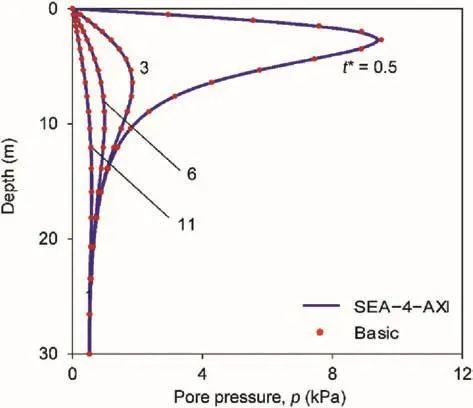
Fig. 11.Profiles of pore pressure with depth at various consolidation times.

Fig. 12.Profiles of settlement at early(t*=0.1)and after long-term(t*=112)consolidations.

Fig. 13.The advancing tunnel problem showing(a)geometry and(b)excavation steps.
Because SEA-4-AXI uses a larger time step size than the basic scheme does,it is very efficient in performing the coupled simulation.The computer runtime for this coupled problem is significantly reduced by 50%,from 120 s in FLAC’s basic scheme to only 60 s in SEA-4-AXI.
6.H-M analysis of an advancing tunnel in deep saturated ground
The potential application of SEA-4-AXI to geotechnical engineering is now demonstrated by simulating the H-M response of an advancing tunnel in deep saturated ground.The advancing tunnel is represented by a two-dimensional(2D)axisymmetric model of an unlined circular excavation of radiusR=2.5 m and at a depth ofH=225 m.The tunnel is excavated through an elastic and saturated medium subjected to total isotropic in situ stress of σo= 4.5 MPa and initialhydrostatic pore pressure ofpo=2.25 MPa.Tunnel at this depth has been reported by Graziani and Boldini(2012)when investigating the influence of H-M coupling on deep tunnel response in clays.Note that an axisymmetric model with a circular boundary and isotropic stress is an appropriate approximation for very deep tunnels where the halfspace conditions corresponding to the ground surface can be disregarded.
The FD grid is also gradually increasing in size toward the right and top boundaries of the model(Fig. 13a).The model boundaries are impermeable except the tunnel wall and face which are made permeable.The advance of the tunnel starts fromx/D=10 to the final tunnel face atx/D=0.The advance is simulated by progressively deactivating 40 FD regions of thicknessΔx=1.25 m(D/4)over an excavation period of 10 d,implying the excavation rate ofva=5 m/d(Fig. 13b).
During deactivation of each regionΔx,a practically instantaneous face advance is being simulated for an excavation period of Δt=0(undrained loading),followed by a drained consolidation for a period ofΔt= Δx/va(drained loading).This step-by-step excavation,represented by the alternating stages of undrained excavation and drained consolidation,is performed until the final tunnel face atx/D=0 is reached.The response of the ground surrounding the tunnel shortly after the final tunnel face is reached is called the short-term response.This state also corresponds to the start of the standstill period(t*=0).This long-term consolidation is performed until the total period of 930 d(t*=100)is reached.The normalized consolidation timet*is calculated ast*=R2/cv(Giraud and Rousset,1996;Li,1999).The groundproperties for this problem are given in Table 3.

Table 3Ground properties for advancing tunnel problem.

Fig. 14.Contours of(a)pore pressure,(b)radial displacement,(c)effective radial and(d)tangential stresses after the short-term consolidation(comparison between SEA-4-AXI and FLAC’s basic scheme).
The simulation in SEA-4-AXI usesΔt=20 minwhile that in FLAC usesΔtcri=5 min.As expected,SEA-4-AXI reduces the computer runtime by 42%,from 520 s in FLAC’s basic scheme to only 300 s in SEA-4-AXI.Discussion in this sectionwill be mainlyon the accuracy comparison between the results from SEA-4-AXI and those from FLAC’s basic scheme.
Fig. 14a-d showsthecontoursofporepressure,radial displacement and stress fields in the short term.The agreement between the contours from SEA-4-AXI and those from FLAC’s basic scheme is very satisfactory.Near the tunnel face,the instantaneous pore pressure develops within a short distance of-0.5Dtoward the advance core(Fig. 14a).For a detailed examination of the induced H-M response in the short-and longterm consolidations,the longitudinal profiles of the pore pressure,radial displacement and effective stresses at the tunnel wall are plotted along the axis of the tunnel(Fig. 15).As can be seen previously,there appears to be a short-term pore pressure buildup up to 2.65 MPa in the region just ahead of the tunnel face(Fig. 15a).In this region,the pore pressure ahead of the core does not have time to dissipate at a speed comparable to the excavation progress due to the nature of ground diffusivity.As drainage proceeds with time,the steep pore pressure gradient decreases,transitioning the pore pressure in the ground towards its steady state as represented by the long-term profile.This non-monotonic behavior and increase of pore pressure above the initial hydrostatic value are analogous to the so-called Mandel-Cryer effect(Mandel,1953;Cryer,1963;Abousleiman et al.,1996;Gutierrez and Lewis,2002).In tunneling,the Mandel-Cryer effect was also observed at the tunnel crown and was caused by the stress concentration in the stiffer zone that is still undrained(Prassetyo and Gutierrez,2016a,b).Due to the dissipation of pore pressure,the radial displacement also increases with time(Fig. 15b)as well as the effective stresses(Fig. 15c).

Fig. 15.Longitudinal profiles of(a)pore pressure,(b)radial displacement,and(c)effective stresses at the tunnel wall after the short-and long-term consolidation.
It can also be seen from Fig. 15 that the agreement between the H-M responses from SEA-4-AXI and FLAC’s basic scheme is excellent with the average percentage difference well below 1.8%in both short-and long-term consolidations.As shown in Tables 4-7,the average percentage differences for pore pressure,radial displacement,effective radial stress,and effective tangential stress in the short term are 0.67%,0.58%,1.31%,and 0.41%,respectively,whilethose in the long term are 1.79%,0.78%,0.92%,and 0.61%,respectively.

Table 4Comparison of the pore pressure p along the axis of the tunnel between SEA-4-AXI and FLAC’s basic scheme.
To capture the transient H-M response during the excavation period,a monitoring point is placed atx/D=5(see the top inset inFig. 16).The excavation starts atx/D=10(att=0)and f i nishes atx/D=0(att=10 d).The agreement in the induced H-M responses with time between SEA-4-AXI and FLAC’s basic scheme is again very satisfactory(Fig. 16).SEA-4-AXI can capture the excess pore pressure that develops before the tunnel face arrives at the monitoring point att=3 d(atx/D=7)before it falls sharply as the tunnel face passes the point.Similar behavior is observed for the convergence history in Fig. 16b,while the corresponding effective stresses are shown in Fig. 16c.Note that the jagged shape in the plot of the H-M response is due to the application of the alternating undrained and drained loadings during the tunnel excavation.This wavy response is expected because the face is advanced at practically instantaneous excavation periodΔt=0(the vertical segment)before it is allowed to consolidate for the period ofΔt=0.25 d(the horizontal segment).The jagged shape has also been reported in the previous coupled analysis of tunneling in shallow ground(Callari and Casini,2005).

Table 5Comparison of the radial displacement uralong the axis of the tunnel between SEA-4-AXI and FLAC’s basic scheme.
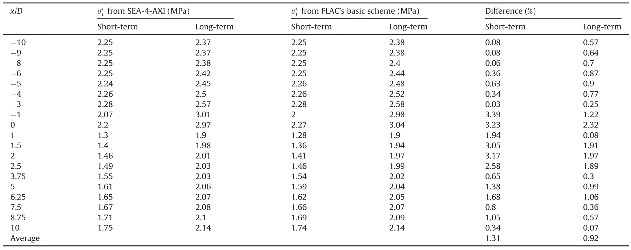
Table 6Comparison of the effective radial stress σ′ralong the axis of the tunnel between SEA-4-AXI and FLAC’s basic scheme.
During the standstill period,the convergence and the extrusion at various locations in the ground ahead of the face are also monitored(Fig. 17a and b,respectively).For graphical presentation,extrusion is regarded as positive deformation in this paper.As expected,the convergence and the extrusion located at the face(0D)are the largest.The convergenceδr0increases by 20%during the standstill period from 1.2 cm att=10 d to 1.4 cm att=930 d,while the face extrusionuex0increases up to 39%,from 3.3 cm to 4.5 cm.Fig. 17c shows the extrusion across the face height at both standstill periods.The face extrusions from SEA-4-AXI are very satisfactory in matching those from FLAC’s basic scheme with the average percentage differences of 0.85%and 0.63%att=10 d and 930 d,respectively(Table 8).At other locations ahead of the face(at-1Dand-2D),the convergence,δr1and δr2,and the core extrusion,uex1anduex2,follow the same trend as those at the face but to a much less degree.

Fig. 16.Transient H-M response during the excavation period for(a)pore pressure,(b)radial displacement,and(c)effective stresses.
7.Conclusions

Fig. 17.Histories of(a)convergence and(b)extrusion during the excavation and standstill periods with the corresponding(c)face profiles.

Table 8Comparison of the face extrusion uex0across the face height between SEA-4-AXI and FLAC’s basic scheme.
The main goal of this paper was to eliminate the drawbacks in the standard ADE so that the new ADE scheme can be coupled with a geomechanical simulator for an ef fi cient simulation of axisymmetric coupled problems in non-uniform grid.This goal was achieved by presenting a novel high-order ADE scheme capable of solving the axisymmetric fluid fl ow problem in a nonuniform grid configuration.The new scheme was derived by performing a non-uniform fourth-order FD approximation of the spatial derivatives of the axisymmetric fluid-diffusion equation.The implicit Crank-Nicolson technique was then applied to the resulting approximation,and the subsequent equation was split into the forward and reverse sweeps,giving rise to the new axisymmetric ADE scheme.The pore pressure solutions obtained from the new scheme were then sequentially coupled with an existing geomechanical simulator in FLAC.This coupling procedure is called the sequentially-explicit coupling technique based on the fourth-order ADE scheme or SEA-4-AXI.By means of von Neumann and truncation error analyses,the new axisymmetric ADE scheme has proven to be unconditionally stable,consistent and fourth-order accurate in space.To demonstrate its application to geotechnical engineering,SEA-4-AXI was used to simulate the H-M interaction of a circular footing and of an advancing tunnel in deep saturated ground.
Because it used large f l ow time steps,SEA-4-AXI has resulted in more computationally efficient H-M simulations than the fully coupled approach using FLAC’s basic f l ow scheme while still maintaining numerical stability and high numerical accuracy.Results from the axisymmetric consolidation of a circular footing and of an advancing tunnel in deep saturated ground showed that SEA-4-AXI reduced computer runtime up to 42%-50%that of FLAC’s basic scheme.Yet,the accuracy of the H-M response was well maintained as shown by the average percentage difference of only 0.5%-1.8%.This increased computational efficiency and high-order accuracy,together with its capability in solving axisymmetric H-M problems in non-uniform domains,suggest that SEA-4-AXI holds great promise for solving larger coupled problems in geotechnical engineering.
Conflicts of interest
The authors wish to confirm that there are no known Conflicts of interest associated with this publication and there has been no significant financial support for this work that could have influenced its outcome.
The authors gratefully acknowledge the support from the University Transportation Center for Underground Transportation Infrastructure at the Colorado School of Mines for partially funding this research under Grant No.69A3551747118 of the Fixing America’s Surface Transportation Act(FAST Act)of U.S.DoT FY2016.The authors also wish to recognize the support from the Center for Underground Construction and Tunneling at the Colorado School of Mines for providing the FLAC key for the simulations performed in this paper.
Appendix
The grid size-dependent constants for Eqs.(33)and(34)are given in Eqs.(A1)-(A5):

where

The constantα0is defined as follows:


The grid size-dependent constants for Eqs.(37)and(38)are given in Eq.(A6):

Abousleiman Y,Cheng AHD,Cui L,Detournay E,Roegiers JC.Mandel’s problem revisited.Géotechnique 1996;46(2):187-95.
Barakat HZ,Clark JA.On the solution of the diffusion equations by numerical methods.Journal of Heat Transfer 1966;88(4):421-7.
Biot MA.General theory of three-dimensional consolidation.Journal of Applied Physics 1941;12(2):155-64.
Bobet A.Characteristic curves for deep circular tunnels in poroplastic rock.Rock Mechanics and Rock Engineering 2010;43(2):185-200.
Callari C,Casini S.Tunnels in saturated elasto-plastic soils:three-dimensional validation of a plane simulation procedure.In:Frémond M,Marceri F,editors.Mechanical modelling and computational issues in civil engineering.Berlin:Springer;2005.p.143-64.
Chapra S,Canale R.Numerical methods for engineers.6th ed.New York:McGraw-Hill;2009.
Crank J,Nicolson P.A practical method for numerical evaluation of solutions of partial differential equations of the heat-conduction type.Mathematical Proceedings of the Cambridge Philosophical Society 1947;43(1):50-67.
Cryer CW.A comparison of the three-dimensional consolidation theories of Biot and Terzaghi.Quarterly Journal of Mechanics and Applied Mathematics 1963;16(4):401-12.
Dean RH,Gai X,Stone CM,Minkoff SE.A comparison of techniques for coupling porous f l ow and geomechanics.Society of Petroleum Engineers Journal 2006;11(1):132-40.
Giraud A,Rousset G.Time-dependent behaviour of deep clays.Engineering Geology 1996;41(1-4):181-95.
Graziani A,Boldini D.influence of hydro-mechanical coupling on tunnel response in clays.Journal of Geotechnical and Geoenvironmental Engineering 2012;138(3):415-8.
Gutierrez M,Lewis R.Coupling of fluid f l ow and deformation in underground formations.Journal of Engineering Mechanics 2002;128(7):779-87.
Hoffman JD.Numerical methods for engineers and scientists.2nd ed.New York:McGraw-Hill;2001.
Itasca.Fast Lagrangian analysis of continua(version 7.00):User’s guide.Minneapolis,USA:Itasca Consulting Group;2011a.
Itasca.Fast Lagrangian analysis of continua:fluid/mechanical interaction.Minneapolis,USA:Itasca Consulting Group;2011b.
Itasca.Fast Lagrangian analysis of continua:FISH in FLAC.Minneapolis,USA:Itasca Consulting Group;2011c.
Li X.Stress and displacement fields around a deep circular tunnel with partial sealing.Computers and Geotechnics 1999;24(2):125-40.
Mandel J.Consolidation des sols(Étude mathématique).Géotechnique 1953;3(7):287-99(in French).
Mazumder S.Numerical methods for partial differential equations:finite difference and finite volume methods.Oxford,UK:Academic Press;2016.
McNamee J,Gibson RE.Plane strain and axially symmetric problems of the consolidation of a semi-infinite clay stratum.Quarterly Journal of Mechanics and Applied Mathematics 1960;13(3):210-27.
Minkoff SE,Stone CM,Bryant S,Peszynska M,Wheeler MF.Coupled fluid f l ow and geomechanical deformation modeling.Journal of Petroleum Science and Engineering 2003;38(1-2):37-56.
Neuzil CE.Hydromechanical coupling in geologic processes.Hydrogeology Journal 2003;11(1):41-83.
Prassetyo SH,Gutierrez M.efficient sequential coupling technique for the simulation of hydro-mechanical interaction in rock engineering.In:Proceedings of the 51st U.S.rock mechanics/geomechanics symposium.Alexandria,USA:American Rock Mechanics Association;2017a.p.1-11.
Prassetyo SH,Gutierrez M.Explicit higher-order ADE solutions for fluid f l ow in the coupled Biot equations.In:Poromechanics VI-proceedings of the 6th biot conference on poromechanics.Reston,USA:American Society of Civil Engineers;2017b.
Prassetyo SH,Gutierrez M.Effect of surface loading on the hydro-mechanical response of a tunnel in saturated ground.Underground Space 2016a;1(1):1-19.
Prassetyo SH,Gutierrez M.influence of embankment Loading on the hydromechanical response of a NATM tunnel in saturated ground.In:Proceedings of the 50th U.S.Rock mechanics/geomechanics symposium.Alexandria,USA:American Rock Mechanics Association;2016b.p.1-8.
Richtmyer RD,Morton KW.Difference methods for initial-value problems.2nd ed.New York:Interscience Tracts in Pure and Applied Mathematics;1967.
Strikwerda JC.Finite difference schemes and partial differential equations.2nd ed.Philadelphia,USA:Society for Industrial and Applied Mathematics;2004.
Wang HF.Theory of linear poroelasticity with applications to geomechanics and hydrogeology.Princeton,USA:Princeton University Press;2000.
 Journal of Rock Mechanics and Geotechnical Engineering2018年2期
- Journal of Rock Mechanics and Geotechnical Engineering的其它文章
- Behavior of diatomaceous soil in lacustrine deposits of Bogotá,Colombia
- Assessment of natural frequency of installed offshore wind turbines using nonlinear finite element model considering soil-monopile interaction
- Behavior of ring footing resting on reinforced sand subjected to eccentric-inclined loading
- A new design equation for drained stability of conical slopes in cohesive-frictional soils
- Investigation of active vibration drilling using acoustic emission and cutting size analysis
- Numerical analysis of Shiobara hydro power cavern using practical equivalent approach
