氧化锌薄膜的微观结构及其结晶性能研究
陈首部,陆 轴,兰 椿
(中南民族大学 电子信息工程学院,武汉 430074)
氧化锌薄膜的微观结构及其结晶性能研究
陈首部,陆 轴,兰 椿
(中南民族大学 电子信息工程学院,武汉 430074)
以普通玻璃作为衬底材料,采用射频磁控溅射方法制备了氧化锌(ZnO)透明导电薄膜,通过X射线衍射(XRD)和X射线光电子能谱(XPS)测试,研究了衬底温度对薄膜微观结构及其结晶性能的影响.结果表明:所制备的ZnO薄膜均为(002)晶面择优取向生长的多晶薄膜,其微观结构和结晶性能与衬底温度密切相关.衬底温度对ZnO薄膜的织构系数TC(hkl)、平均晶粒尺寸、位错密度、晶格应变和晶格常数都具有不同程度的影响,当衬底温度为800 K时,ZnO薄膜样品的织构系数TC(002)最高(4.929)、平均晶粒尺寸最大(20.91 nm)、位错密度最小(2.289×10¹⁵line·m-2)、晶格应变最低(2.781×10⁻³),具有最高的(002)晶面择优取向生长性和最佳的微观结构性能.
氧化锌;薄膜;微观结构;结晶性能
作为第三代新型半导体材料的主要代表之一,氧化锌(ZnO)不仅自然储量丰富、价格低廉、绿色环保,同时还具有优异的光电、光敏、压电和压敏等性质.它与硫化锌(ZnS)和氮化镓(GaN)相比,ZnO在室温条件下具有较宽的直接带隙和较高的自由激子结合能,是制备光电功能器件的优良材料,已被广泛应用于太阳能电池[1-5]、发光显示器[6-11]、半导体激光器[12]、紫外探测器[13]、声表面波器件[14]以及触摸控制面板[15]等领域具有广阔的应用前景.
目前,制备ZnO薄膜的方法多种多样,如水热法[16]、溶胶-凝胶法[17]、化学气相沉积法[18]、原子层沉积法[19]、脉冲激光沉积法[20]、喷雾热分解法[21]和磁控溅射法[22-25]等,其中磁控溅射技术具有工艺简单、成膜均匀、致密性好、成本低廉、易于大面积制备等优点,因此得到了业界的广泛应用.ZnO薄膜的晶体质量及其性能与其制备工艺参数密切相关,其中影响较大的工艺因素有衬底温度、溅射功率和工作压强等,因此深入研究溅射工艺参数对ZnO薄膜微观结构的影响具有十分重要的意义.本文以普通玻璃作为衬底材料,采用射频磁控溅射方法制备ZnO薄膜样品,通过X射线衍射(XRD)和X射线光电子能谱(XPS)测试表征,研究了衬底温度对ZnO薄膜微观结构及其结晶性能的影响.
1 实验部分
1.1 衬底处理
采用普通玻璃作为衬底材料,切割成大小为30 mm×30 mm的方块,实验时按照如下程序对玻璃衬底进行处理:(1)采用丙酮擦拭衬底表面,并用清水冲洗干净;(2)依次使用丙酮、无水乙醇和纯净水对衬底进行超声清洗13 min,以去除衬底表面的微粒和有机污染物;(3)在无水乙醇中煮沸,吹干待用.
1.2 样品制备
利用射频磁控溅射方法在玻璃衬底上制备ZnO薄膜样品,所用实验设备为KDJ-567型高真空复合镀膜系统,溅射源为直径50 mm、厚度4 mm的ZnO陶瓷靶材,它以ZnO粉体(999.99%)为原料通过常压固相烧结工艺制成.溅射制备ZnO薄膜样品之前,将溅射室的真空度抽至5×10⁻⁴Pa后通入99.999%的高纯氩气作为工作气体,并先采用氩等离子体对玻璃衬底表面清洗7 min,然后再预溅射10 min以清洁靶材表面和稳定系统,提高沉积ZnO薄膜样品的质量.实验时,衬底与靶材之间的距离为75 mm、溅射功率为200 W、工作气压为0.5 Pa、沉积时间为25 min、衬底温度为600~800 K.
1.3 样品表征
通过X射线衍射仪(Bruker advance D8型,德国Bruker公司)对ZnO薄膜样品进行晶体结构表征,测试时使用Cu Kα射线源(波长λ=0.1541 nm),采用θ-2θ连续扫描方式,扫描速度为10°/min,扫描步长为0.0164 Å,扫描范围为20°≤2θ≤70°,工作电压为40 kV,工作电流为40 mA.利用X射线光电子能谱仪(VG Multilab 2000型,美国Thermo Electron公司)对ZnO薄膜样品进行XPS分析,测试时本底真空度为2.0×10⁻⁶Pa,X射线源为单色Al Kα射线源(hv=1486.60 eV),采用C 1s结合能(284.60 eV)作为内标,对所有测试谱峰进行荷电校正.所的测试均在室温条件下完成.
2 结果与讨论
图1为不同衬底温度时ZnO薄膜样品的XRD图谱,由图可见,在2θ为20 °~70°的扫描范围内,所有ZnO薄膜样品在峰位2θ为30.9°和34.1°附近都出现了2个特征峰,比对ZnO的标准PDF卡片(JCPDS #36-1451,见图1)可以看出,这2个衍射峰分别与ZnO的(100)和(002)晶向相吻合.
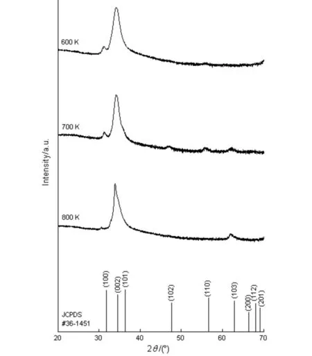
图1 ZnO薄膜样品的XRD图谱Fig.1 XRD patterns of the ZnO samples
另外从图1中还可看到,衬底温度不同时,ZnO薄膜样品还存在有其它晶向的特征峰,如衬底温度为600和800 K时,分别显示有(110)和(103)晶面的衍射峰,而衬底温度为700 K时,则显示有(110)、(102)和(103)等多个晶面的衍射峰.上述XRD图谱结果表明,所制备的ZnO样品均为多晶薄膜,并具有六角纤锌矿结构.观察图1的XRD图谱还可以看出,衬底温度对衍射峰位2θ的影响较小,而对各个晶向的衍射峰强度的影响较大,为了评估ZnO薄膜样品沿某一晶面(hkl)的择优取向程度,本文采用织构系数(TC(hkl))来定量表征样品沿不同晶面生长的取向程度.织构系数TC(hkl)定义如下[26]:
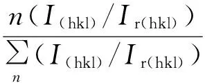
(1)
(1)式中,下标h、k、l表示密勒指数,TC(hkl)表示(hkl)晶面的织构系数,I(hkl)为ZnO薄膜样品在(hkl)晶面的衍射强度,Ir(hkl)为标准ZnO粉未试样(JCPDS #36-1451)在(hkl)晶面的衍射强度,n为计算时所取的衍射峰数目.TC(hkl)的数值越大,说明薄膜中有更多的晶粒沿(hkl)晶面生长,即薄膜在(hkl)晶面的择优取向性越好.表1列出了不同衬底温度时ZnO薄膜样品的织构系数TC(hkl),由表1可见,当衬底温度为600、700和800 K时,ZnO薄膜样品的TC(002)值分别为4.916、4.363和4.929,均远远高于其它晶面的TC(hkl)数值,这说明所制备的ZnO样品都表现出明显的(002)晶面择优取向生长特征,并且衬底温度升高时,TC(002)的数值呈现出先减小后增大的变化趋势.可见,衬底温度从600 K增加到800 K时,虽然没有改变ZnO薄膜(002)择优取向生长特征,但是对其择优取向程度有一定的影响,当衬底温度为800 K时所制备的ZnO样品具有最高的(002)择优取向程度.其原因是:ZnO薄膜在(002)晶面的表面自由能密度是最小的,因此晶粒沿(002)晶面具有生长优势,在生长过程中晶粒极易沿c轴即(002)晶面平行于衬底的方向生长[27,28].

表1 ZnO薄膜样品的织构系数Tab.1 The values of TC(hkl) for the ZnO samples
图2为衬底温度800 K时所制备ZnO薄膜样品的XPS能谱图,由图2可见,XPS图谱上除了Zn和O原子的光电子特征峰之外,在284.6 eV处还存在有C 1s特征峰,这可能是由于溅射镀膜时油扩散泵污染或者ZnO薄膜样品暴露在大气中吸附了CO2所造成的[29].
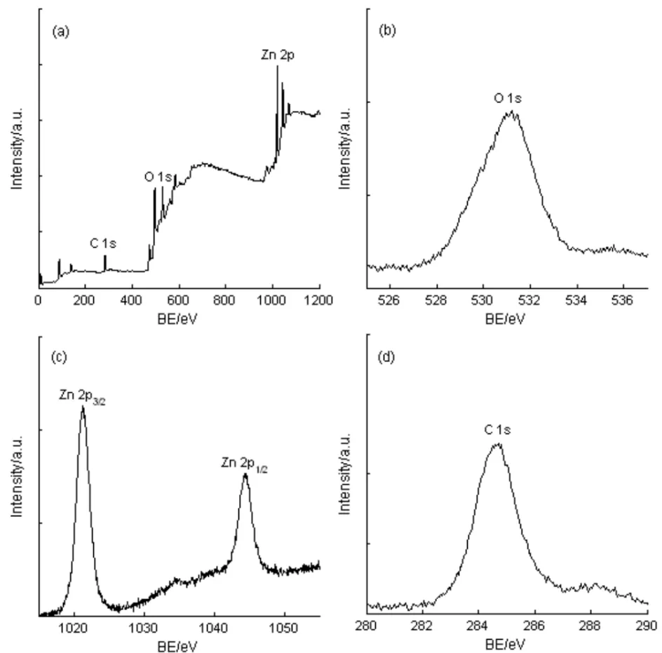
图2 衬底温度为700 K时所制备ZnO样品的XPS能谱图Fig.2 XPS spectra of the ZnO sample prepared at substrate temperature of 700 K
图3(a)为不同衬底温度时ZnO薄膜样品的(002)衍射峰半高宽(B)数值,可见半高宽B的值与衬底温度密切相关,衬底温度增加时,半高宽B单调减小,当衬底温度为800 K时,ZnO薄膜样品(002)衍射峰的半高宽B最小值为0.392°,说明衬底温度为800 K时制备的ZnO薄膜样品具有最大的晶粒尺寸和最佳的结晶性能.ZnO薄膜样品的平均晶粒尺寸(D)可以根据谢乐公式[30]计算:

(2)
(2)式中,K为谢乐常数(这里取K=0.89),θ为所(002)晶面的布拉格角,B为(002)衍射峰的半高宽数值,λ为XRD测试时的X射线波长[31].图3(b)为不同衬底温度时ZnO薄膜样品的平均晶粒尺寸D,从图中3(b)看出,衬底温度对ZnO样品的平均晶粒尺寸D具有明显的影响.当衬底温度为600~800 K时,ZnO样品的平均晶粒尺寸D为9.73~20.91 nm,平均晶粒尺寸D随衬底温度增加而增大,当衬底温度为800 K时,ZnO薄膜样品的D值最大(20.91 nm).
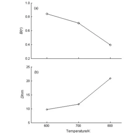
图3 不同衬底温度时ZnO样品的B和DFig.3 The B and D values of the ZnO sample prepared at different substrate temperatures
ZnO薄膜样品的位错密度(δ)[31]利用公式(3)计算获得:

(3)
(3)式中,D为ZnO薄膜样品的平均晶粒尺寸.ZnO薄膜样品的位错密度δ随衬底温度变化的曲线如图4所示,可以看出,随着衬底温度的增加,δ呈现出单调减小的变化趋势,当衬底温度为800 K时,ZnO薄膜样品的位错密度δ最小为2.289×10¹⁵line·m-2.
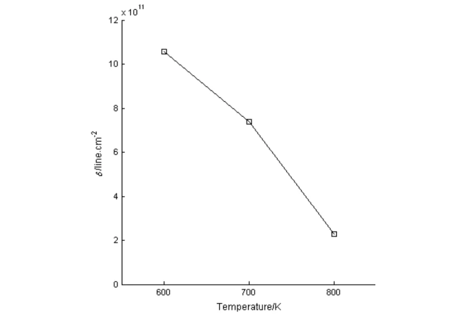
图4 不同衬底温度时ZnO样品的δ值Fig.4 The δ values of the ZnO sample prepared at different substrate temperatures
ZnO薄膜样品的晶格应变(ε)可由下式[32]计算:
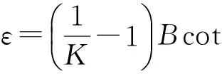
(4)
(4)式中,K为由谢乐常数,θ为所(002)晶面的布拉格角,B为(002)衍射峰的半高宽数值.不同衬底温度时ZnO薄膜样品的ε值如图5所示,从图5看出,衬底温度对ZnO薄膜ε值具有明显的影响,ε值随着衬底温度的增加而逐渐减小,当衬底温度为800 K时,ZnO薄膜样品具有最小的晶格应变ε,其值为2.781×10⁻³.
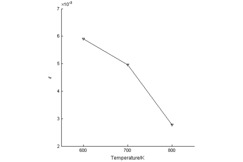
图5 不同衬底温度时ZnO样品的ε值Fig.5 The ε values of the ZnO sample prepared at different substrate temperatures
ZnO薄膜样品为六角纤锌矿结构,其晶格常数由公式(5)确定[33,34]:
(5)
(5)式中,a和c为ZnO样品的晶格常数.对于(002)晶面,由(5)式可得:

(6)
对于(100)晶面,(5)式可简化为:
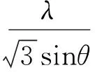
(7)
图6为不同衬底温度时ZnO薄膜样品的晶格常数a、c和c/a的数值,从图6看出,衬底温度增大时,a先减后增、c单调增加、c/a先增后减,在衬底温度的变化范围为600~800 K时,a、c和c/a的数值范围分别为0.32845~0.33608 nm、0.52259~0.52857 nm和1.57275~1.59411,这些结果与标准ZnO试样(JCPDS #36-1451)数据(a=0.32498 nm、c=0.52066 nm、c/a=1.60213)是一致的.文献[35,36]在研究掺钇ZnO和掺锂ZnO薄膜时也有类似的报道.
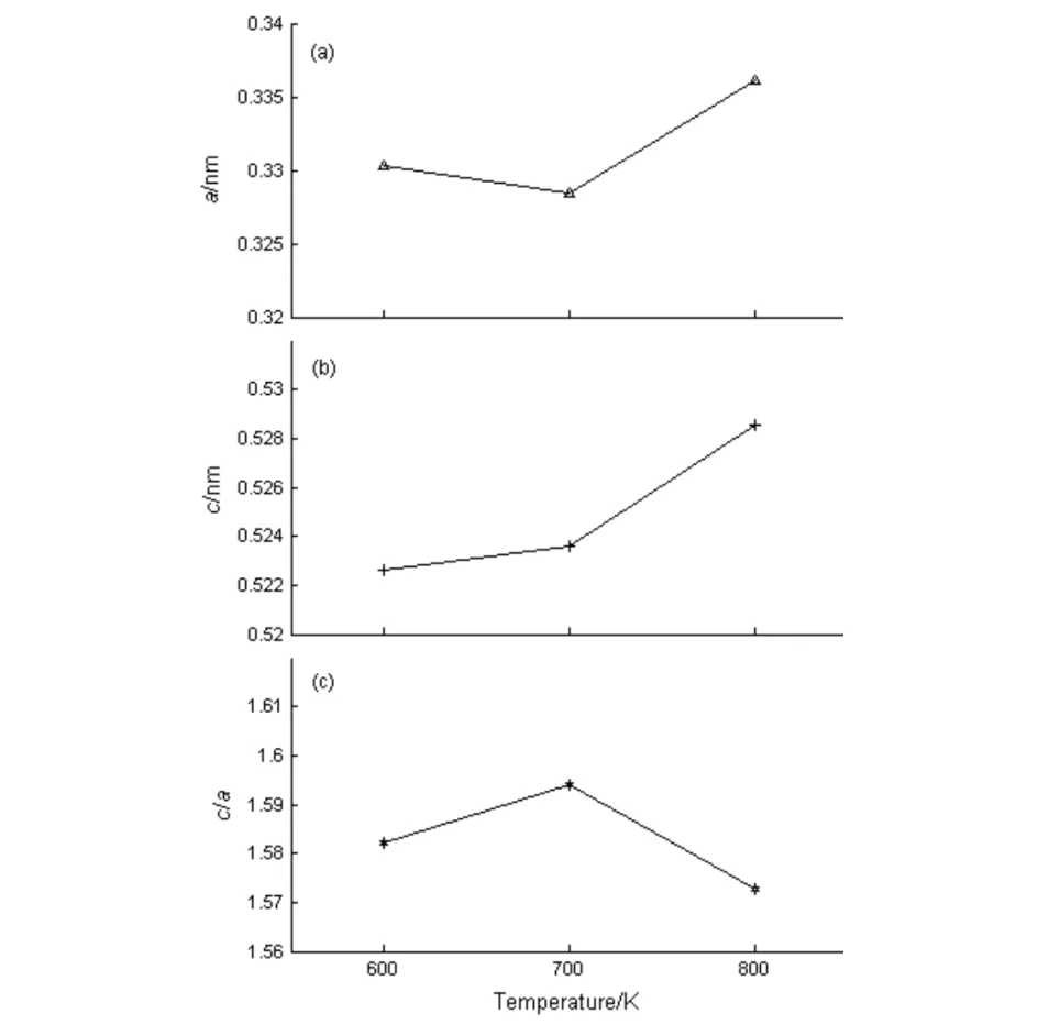
图6 不同衬底温度时ZnO样品的a、c和c/aFig.6 The values of a, c and c/a for the ZnO sample prepared at different substrate temperatures
ZnO薄膜样品的Zn-O键长(L)[37]可由公式(8)计算获得:

(8)
(8)式中,a和c为ZnO薄膜样品的晶格常数,u与a、c之间满足关系式[37]:

(9)
图7为ZnO样品薄膜Zn-O键长L随衬底温度的变化曲线,从图可知,衬底温度对ZnO薄膜的Zn-O键长L具有一定的影响,当衬底温度为600、700和800 K时,ZnO样品的Zn-O键长L值分别为0.2002、0.19957和0.20337 nm,其结果与标准ZnO试样(JCPDS No. 36-1451)数据(L=0.19778 nm)基本一致.Anandan等人[35]和Srinivasan小组[36]在研究掺杂ZnO薄膜时也报道过类似的结果.
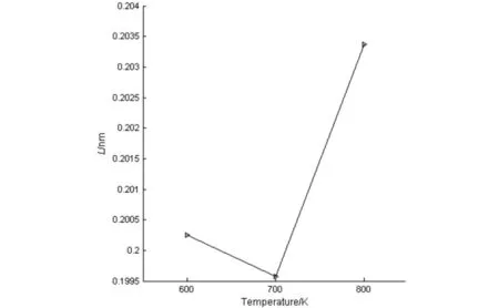
图7 不同衬底温度时ZnO样品的L值Fig.7 The L values of the ZnO sample prepared at different substrate temperatures
3 结语
采用ZnO陶瓷靶为溅射源材料,利用射频磁控溅射技术在普通玻璃衬底上制备了ZnO薄膜样品,通过XRD和XPS测试表征,研究了衬底温度对ZnO薄膜样品微观结构及其结晶性能的影响.结果表明,所有ZnO薄膜样品均为六角纤锌矿结构的多晶薄膜,并且衬底温度对薄膜生长特性及其微观结构性能具有明显的影响.衬底温度升高时,ZnO薄膜的织构系数TC(002)、晶格常数a和Zn-O键长L先减后增,平均晶粒尺寸D和晶格常数c单调增加,而位错密度δ和晶格应变ε则单调减小,当衬底温度为800 K时,ZnO薄膜样品的织构系数TC(002)最高为4.929、平均晶粒尺寸D最大为20.91 nm、位错密度δ最小为2.289×10¹⁵line·m-2、晶格应变δ最低为2.781×10⁻³,所制备的ZnO薄膜具有最高的(002)晶面择优取向生长性和最好的微观结构性能.
[1] Liu H, Avrutin V, Izyumskaya N, et al. Transparent conducting oxides for electrode applications in light emitting and absorbing devices [J]. Superlattices and Microstructures, 2010, 48 (5): 458-484.
[2] Lee D, Bae W K, Park I, et al. Transparent electrode with ZnO nanoparticles in tandem organic solar cells [J]. Solar Energy Materials and Solar Cells, 2011, 95 (1): 365-368.
[3] Bekci D R, Erten-Ela S. Effect of nanostructured ZnO cathode layer on the photovoltaic performance of inverted bulk heterojunction solar cells [J]. Renewable Energy, 2012, 43 (1): 378-382.
[4] Sio A D, Chakanga K, Sergeev O, et al. ITO-free inverted polymer solar cells with ZnO:Al cathodes and stable top anodes [J]. Solar Energy Materials and Solar Cells, 2012, 98 (1): 52-56.
[5] Tian C-S, Chen X-L, Ni J, et al. Transparent conductive Mg and Ga co-doped ZnO thin films for solar cells grown by magnetron sputtering: H2 induced changes [J]. Solar Energy Materials and Solar Cells, 2014 125 (1): 59-65.
[6] Kim H, Horwitz J S, Kim W H, et al. Doped ZnO thin films as anode materials for organic light-emitting diodes [J]. Thin Solid Films, 2002, 420-421 (1): 539-543.
[7] Cao H T, Sun C, Pei Z L, et al. Properties of transparent conducting ZnO:Al oxide thin films and their application for molecular organic light-emitting diodes [J]. Journal of Materials Science: Materials in Electronics, 2004, 14 (1): 169-174.
[8] Kim H, Piqué A, Horwitz J S, et al. Effect of aluminum doping on zinc oxide thin films grown by pulsed laser deposition for organic light-emitting devices [J]. Thin Solid Films, 2000, 377-378 (1): 798-802.
[9] Wang L, Swensen J S, Polikarpov E, et al. Highly efficient blue organic light-emitting devices with indium-free transparent anode on flexible substrates [J]. Organic Electronics, 2010, 11 (9): 1555-1560.
[10] Chen M, Pei Z L, Sun C, et al. ZAO: an attractive potential substitute for ITO in flat display panels [J]. Materials Science and Engineering B, 2001, 85 (2-3): 212-217.
[11] Yamamoto N, Makino H, Osone S, et al. Development of Ga-doped ZnO transparent electrodes for liquid crystal display panels [J]. Thin Solid Films, 2012, 520 (12): 4131-4138.
[12] Pflumm C, Karnutsch C, Gerken M, et al. Parametric study of modal gain and threshold power density in electrically pumped single-layer organic optical amplifier and laser diode structures [J]. IEEE Journal of Quantum Electronics, 2005, 41 (3): 316-336.
[13] Wang H,Long H,Chen Z,et al.Fabrication and characteri-
zation of alternating-current-driven ZnO-based ultraviolet light-emitting diodes [J]. Electronic Materials Letters, 2015, 11 (4): 664-669.
[14] Asmar R A, Atanas J P, Ajaka M, et al. Characterization and Raman investigations on high-quality ZnO thin films fabricated by reactive electron beam evaporation technique [J]. Journal of Crystal Growth, 2005, 279 (2): 394-402.
[15] Tsay C-Y,Fan K-S,Lei C-M. Synthesis and characterization of sol-gel derived gallium-doped zinc oxide thin films [J]. Journal of Alloys and Compounds, 2012, 512 (1): 216-222.
[16] Jin D-H, Kim D, Seo Y, et al. Morphology-controlled synthesis of ZnO crystals with twinned structures and the morphology dependence of their antibacterial activities [J]. Materials Letters, 2014, 115 (2): 205-207.
[17] Malek M F, Mamat M H, Musa M Z, et al. Thermal annealing-induced formation of ZnO nanoparticles: Minimum strain and stress ameliorate preferred c-axis orientation and crystal-growth properties [J]. Journal of Alloys and Compounds, 2014, 610 (2): 575-588.
[18] Martin A, Espinos J P, Justo A, et al. Preparation of transparent and conductive Al-doped ZnO thin films by ECR plasma enhanced CVD [J]. Surface & Coating and Technology, 2002, 151-152 (1): 289-293.
[19] Oh B-Y, Kim J-H, Han J-W, et al. Transparent conductive ZnO:Al films grown by atomic layer deposition for Si-wire-based solar cells [J]. Current Applied Physics, 2012, 12 (2): 273-279.
[20] Zhang D, Wang C, Zhang F. Oxygen pressure and measurement temperature dependence of defects related bands in zinc oxide films [J]. Vacuum, 2010, 85 (1): 160-163.
[21] Sahay P P, Tewari S, Nath R K. Optical and electrical studies on spray deposited ZnO thin films [J]. Crystal Research Technology, 2007, 42 (5): 723-729.
[22] Lee J, Gao W, Li Z, et al. Sputtered deposited nanocrystalline ZnO films: A correlation between electrical, optical and microstructural properties [J]. Applied Physics A, 2005, 80 (11): 1641-1646.
[23] Jayaraj M K, Antony A, Ramachandran M. Transparent conducting zinc oxide thin film prepared by off-axis rf magnetron sputtering [J].Bulletin Materials Science, 2002, 25 (2): 227-230.
[24] Heo G S, Gim I G, Park J W, et al. Effects of substrate temperature on properties of ITO-ZnO composition spread films fabricated by combinatorial RF magnetron sputtering [J]. Journal of Solid State Chemistry, 2009, 18 (12)2: 2937-2940.
[25] 孙奉娄, 惠述伟. 衬底温度对射频溅射沉积ZAO透明导电薄膜性能的影响 [J]. 中南民族大学学报(自然科学版), 2009, 28 (2): 10-13.
[26] Valle G G, Hammer P, Pulcinelli S H, et al. Transparent and conductive ZnO:Al thin films prepared by sol-gel dip-coating [J]. Journal of the European Ceramic Society, 2004, 24 (4): 1009-1013.
[27] Caglar Y, Ilican S, Caglar M, et al. Effects of In, Al and Sn dopants on the structural and optical properties of ZnO thin films [J]. Spectrochimica Acta Part A, 2007, 67 (10): 1113-1119.
[28] Lin S-S, Huang J-L. Effect of thickness on the structural and optical properties of ZnO films by r.f. magnetron sputtering [J]. Surface & Coatings Technology, 2004, 185 (2): 222- 227.
[29] Briggs D. Handbook of X-ray and ultraviolet photoelectron spectroscopy [M]. London: Heyden & Son Ltd., 1977.
[30] 陈首部, 孙奉娄. 基体温度对氮化钛涂层微观结构的影响 [J]. 中南民族大学学报(自然科学版), 2013, 32 (4): 59-63.
[31] Lu Z, Long L, Zhong Z, et al. Structural characterization and optoelectrical properties of Ti-Ga co-doped ZnO thin films prepared by magnetron sputtering[J]. Journal of Materials Science: Materials in Electronics, 2016, 27 (3): 2875-2884.
[32] Matheswaran P, Gokul B, Abhirami K M, et al. Thickness dependent structural and optical properties of In/Te bilayer thin films [J]. Materials Science in Semiconductor Processing, 2012, 15 (5): 486-491.
[33] Pankove J I. Optical processes in semiconductors [M]. New York: Dover Publications, 1975.
[34] Zhang T, Zhong Z. Effect of working pressure on the structural, optical and electrical properties of titanium-gallium co-doped zinc oxide thin films [J]. Materials Science-Poland, 2013, 31 (3): 454-461.
[35] Anandan S, Muthukumaran S. Influence of Yttrium on optical, structural and photoluminescence properties of ZnO nanopowders by sol-gel method [J]. Optical Materials, 2013, 35 (12): 2241-2249.
[36] Srinivasan G, Kumar R T R, Kumar J. Li doped and undoped ZnO nanocrystalline thin films: a comparative study of structural and optical properties [J]. Journal of Sol-Gel Science and Technology, 2007, 43 (2): 171-177.
[37] Murtaza G, Ahmad R, Rashid M S, et al. Structural and magnetic studies on Zr doped ZnO diluted magnetic semiconductor [J]. Current Applied Physics, 2014, 14 (2): 176-181.
MicrosructureandCrystallineCharacteristicsofZincOxideThinFilms
ChenShoubu,LuZhou,LanChun
(College of Electronic Information Engineering, South-Central University for Nationalities, Wuhan 430074, China)
The transparent conducting oxide thin films of zinc oxide (ZnO) were deposited on glass substrates by radio-frequency magnetron sputtering method. The influence of substrate temperature on the mirostructure and crystalline characteristics of ZnO thin films was investigated by X-ray diffraction (XRD) and X-ray photoelectron spectroscopy (XPS), respectively. The results indicate that the deposited thin films with the hexagonal crystal structure are polycrystalline and have a strongly preferred orientation of (002) plane. The mirostructure and crystalline characteristics of the thin films are observed to be subjected to the substrate temperature. When the substrate temperature is 800 K, the deposited ZnO sample exhibits the best crystalline and microstructural properties, with the highest texture coefficient of (002) plane of 4.929, the largest average grain size of 20.91 nm, the minimum dislocation density of 2.289×10¹⁵line·m-2and the lowest lattice strain of 2.781×10⁻³.
zinc oxide; thin film; microstructure; crystalline characteristics
2017-05-28
陈首部(1964-), 男, 高级工程师, 研究方向: 等离子体应用技术, E-mail: chensb64@sohu.com
湖北省自然科学基金资助项目(2011CDB418)
TM914
A
1672-4321(2017)04-0067-06

