A Novel Low Density Parity Check Coded Differential Amplitude and Pulse Position Modulation Free-Space Optical System for Turbulent Channel
Yin Liang, Hua Zhang, Limin Chen*, Xiaoping Liu, Xuehong Lin
1 School of Mechatronics Engineering, Department of Electronic Information Engineering, Nanchang University, Nanchang 330031, China 2 School of Information Engineering Nanchang University, Nanchang 330031, China
3 Department of Systems and Computer Engineering, Carleton University, Ottawa, ON, K1S 5B6, Canada
4 School of Information and Communication Engineering, Beijing University of Posts and Telecommunications, Beijing 100876, China
* The corresponding author, email: chenlimin@ncu.edu.cn.
I. INTRODUCTION
Free-space optical communication (FSO) is a green optical communication approach with higher energy efficiency, which has intrinsic properties of more simplified and rapid deployment than traditional optical fiber communication[1-3]. So it is more widely used in emergency communication[4] and is preliminary applied to short-range communication and emerging autonomous robot datalink[5]. Differential Amplitude and Pulse Position Modulation (DAPPM) is a combined modulation which not only inherits advantages of High efficiency from Pulse Position Modulation (PPM) and Pulse Amplitude Modulation (PAM)[6] but also improves the frequency efficiency from Pulse Position Modulation (PPM) and promotes energy ef ficiency from Amplitude shift keying (ASK)[7].Consequently, DAPPM lower energy cost for achieving same Bit-Error-Rate (BER). Substantially reducing the optical radiation power means longer working life of light source and associated optical devices. So it makes more sense to improve reliability of DAPPM for green FSO.
Low-Density-Parity-Check (LDPC) is an enhanced linear block code with perfect net coding gain as well as relatively low decoding complexity[8]. Researches on PPM and forward error correction (FEC) are growing these years. TCM-PPM, LDPC-PPM and LDPC-MI-MO[9,10] were primarily concerned. A LDPC coded DAPPM FSO system show considerable BER performance improvement which has been verified by Monte Carlo simulation[11].However, a DAPPM FSO scheme with LDPC coding has been less concerned, and the optimal modification of classical DAPPM for confronting the strong turbulent is less investigated. To improve its efficiency and reliability, a novel DAPPM FSO together with LDPC codes was proposed and investigated. The innovation reflects on that a set of amplitude sequence values according to the specific time slot selection, and the selected time slot demapping rather than traditional ones such as {1, 2,…,N}. In this new system, BER at the same Eb/N0decreases, namely the transmit power can be saved for approaching the same BER, which is the essence of “Green” communication. Theoretical analysis shows well energy efficiency and decoding reliability, meanwhile, the Monte-Carlo simulation demonstrated its better BER performance over traditional scheme.
This paper is organized as follows. Besides general introduction in Section 1, strong turbulent FSO channel is introduced for the modified DAPPM in Section 2. A partly equidifferent mapping method is proposed,and a novel green DAPPM FSO scheme is constructed based on optimal receiver. Optimization of partly equidifferent mapping and soft demodulation for subsequent LDPC decoder are derived in Section 3. How LDPC works in this system is described in Section 4. The proposed DAPPM FSO system is simulated, and simulation results and discussing are presented in Section 5. Finally the definite conclusion is brought in Section 6.
II. MODELLING OF TURBULENT CHANNEL
Considering the intensity fluctuation of the transmitted laser beam, the turbulent channel can be approximated by three kinds of probability models based on Rytov theory. That is,in strong turbulence, the probability density function (PDF) obeys negative exponential distribution with probability density function in (1) while in weak and moderate turbulence obey log-normal and gamma-gamma distribution with the corresponding PDF in (2) and (3)respectively, together with (4), (5) and (6) as supplementary specification[12,13].
Under strong turbulence condition, the DAPPM received signal intensity follows the negative exponential distribution as shown in(1), in which I and I0stand for the intensity of the received signal and the transmitted signal respectively.
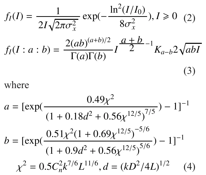
The study for moderate and weak situations will be presented in the future research, due to the complexity of special hypergeometric functions as shown in (3) and (4). Here the negative exponential distribution corresponding area is scintillation index≥1. The index can be expressed by= exp()-1, whereequals 0.307k7/6L11/6,stands for the refractive index structure parameter, k for the wave number and L for transmission distance.
To conduct a Monte-Carlo simulation of green LDPC coded DAPPM FSO system,the channel effect must be most importantly considered. As for a random variable obeying negative exponential distribution, direct generation is available. Based on its inverse function, the random variable obeying negative exponential distribution is constructed by an equidistribution random variable x~U(0,1).The probability density function (PDF) fI(I)is integrated to be the cumulative distribution function FI(I), then its inverse function Finv(x)is obtained to calculate upper bound of channel output:

Then the channel output I can be converted by the input signal intensity I0and the probability x.
III. THE NOVEL DAPPM SCHEME
Before an amplitude-modified DAPPM scheme is proposed, the reason why DAPPM is selected as the prototype of green modulation is explained here.
Due to the high energy efficiency, M-ary PPM shows its advantage over traditional amplitude and phase modulation. The energy efficiency ηPPMis obviously higher than that of M-ary ASK and M-ary PSK.

Here Ppand Parepresent the peak power and average power respectively. Higher ηPPMstands for larger peak power of the same average power so as to save energy. DAPPM is the evolutional version of PPM. The energy efficiency ηDAPPMis nearly the same with ηPPMbecause that of amplitude modulation is nearly 1 in high level (more than 4-ary) as follows,

where A and M stand for the total number of mapping pulse amplitude and position.
However, the frequency efficiency of DAPPM is A times as large as that of PPM, with only a little BER performance loss. That’s why it is selected as a modulation scheme. Notice that the modulation and demodulation are largely different from MASK and MPSK, the latter part of this section aimed at analyzing specific process of how the amplitude-modified DAPPM works and what it prepares for subsequent LDPC decoding.
3.1 Modulation of green DAPPM
To simplify the description, the rectangular non-return-to-zero (NRZ) shaped DAPPM baseband signal is expressed as:

Notice that Trec(t) is a unit rectangular array with symbol width Tc=Ts/M while Ppis a modified power which makes the average power to be normalized. In the novel scheme of 4×4 and 4×8 green DAPPM (abbreviated to GDAPPM), the amplitude and position characteristic variable a and m are special valued as shown in table I. Here v is an optimized pa-rameter depended on modulation and channel models, the level interval d equals (4-v)/3. The amplitude set {0,v,v+d,v+2d,v+3d,4} is partly equidifferent to achieve lower erroneous decision probability.
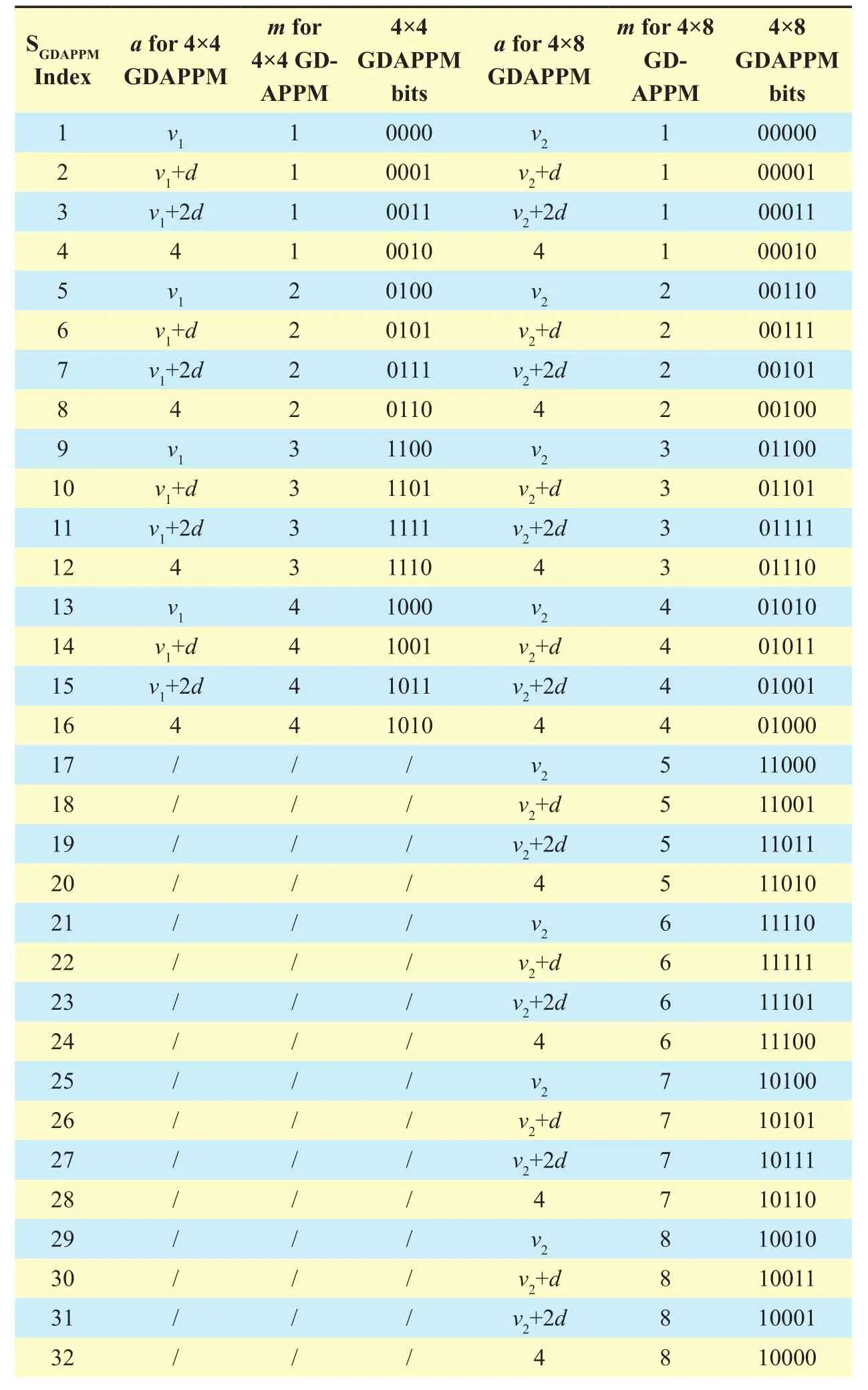
Table I Parartly equidifferent mapping rule of 4×4 and 4×8 gdappm
Each value of a and m in a symbol stands for the amplitude and time slot index of a given time slot. Here a can be vx, vx+d, vx+2d and 4, d=(4-vx)/3, v1, v2stand for component amplitude value of 4×4 and 4×8 GDAPPM respectively. Because of relationship between the amplitude mapping and demodulation principle, the optimal value of vxwas discussed in section 3.2 comprehensively and critically.The bit sequence of each symbol x5x4x3x2x1are differential bits for GDAPPM mapping.Additionally, since there is similarity in 4×4 and 4×8 GDAPPM signals, the waveform SGDAPPM(t) of 4×4 GDAPPM signal is shown in Figure.1.
The mapped baseband signal is modulated by an optical modulator and then transmitted into the strong turbulence channel. Among bits, the amplitude control bits x1, x2are vulnerable to be interfered. Gray mapping rules adopted here can effectively minimize the loss of nearby amplitude error decision so as to reduce bit- error rate as possible.
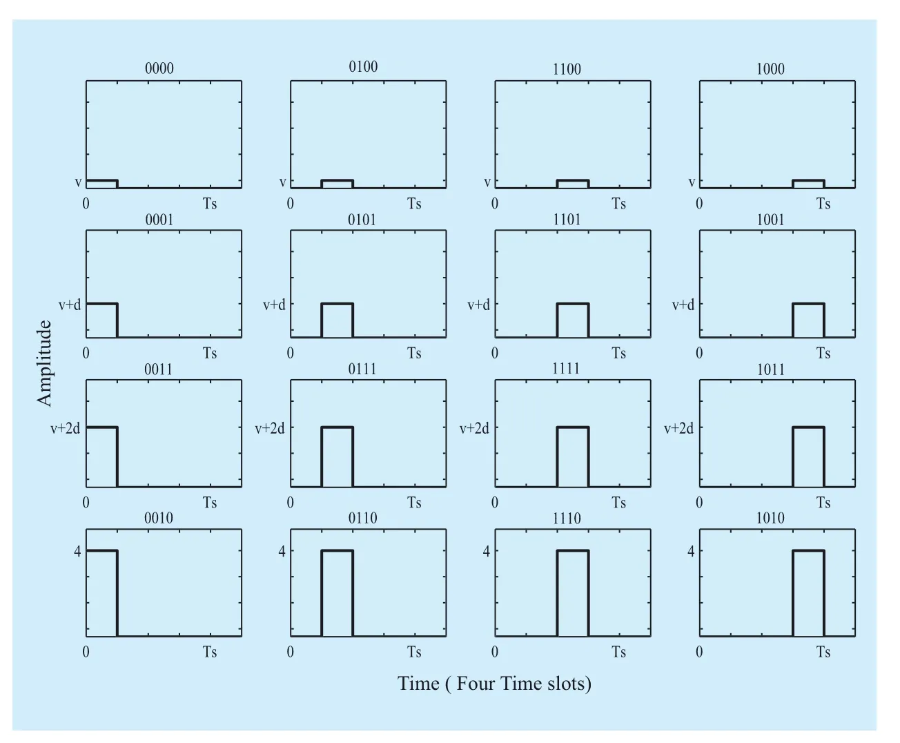
Fig. 1 Waveform Array of 4×4 GDAPPM
3.2 Demodulation of GDAPPM
Now take 4×8 GDAPPM as an example to analyze the demodulation process, received GDAPPM signal is firstly demodulated to be an array of baseband signal rx=(rx1,rx2,…,rx8)by a corresponding matched filter bank. System initialization and the optimal coefficient vxsearching process are shown as Figure 2.As cooperative communication, the optimal amplitude coefficient vxis given by the initialization protocol. Following the similar process described in Figure 2, the time slot position of the pulse in a symbol interval is estimated by maximum likelihood criterion, and then the maximum matching output is demapped into bits or export to cascading decoder as soft values.
The error probability of the GDAPPM detector would be analyzed as following. In the amplitude set {vx,vx+d,vx+2d,4}, the optimum of vxcan be found based on the statistics channel model. Considering that the pulse amplitude a may be interfered by turbulence-induced fading and additive white Gaussian noise (AWGN). The receiving signal x is modeled by the sum of xteand xtn, in which xteand xtnrespectively follows an exponential and a Gaussian distribution, so the correct-decision probability Pstep2can be worked out as follows:
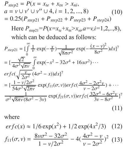

The sub-probability of Sstep22, Sstep23and Sstep24can be similarly calculated by replacing“v” as “v+d”, “v+2d” and “4” respectively.
After estimating the pulse position, the correct decision probability of demapping amplitude can be derived, which is denoted by Pstep3.Notice that decision threshold VT1, VT2, VT3can be set as follows respectively based on maximum posteriori probability principle:

Accordingly, Pstep3can be expressed as follows:
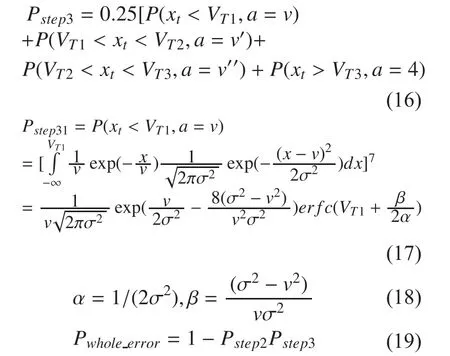
The sub-probability Sstep32, Sstep33and Sstep34can be similarly worked out by replacing “v”as “v+d ”, “v+2d ” and “4” respectively .
By applying the formula for whole error probability (21) and adopting a sequence searching algorithm from 0 to 4 for the cost function of the minimum error probability, the optimum v* is obtained. For instance, in 4×8 GDAPPM with σ2=1, the value of v* is 0.36,meanwhile in case of 4×4 DAPPM, the optimal value of v* changes to 0.12.
All above the hard demodulation for GDAPPM FSO is discussed. When LDPC coding is employed, the hard demodulation needs to be replaced by a soft demodulation with log-likelihood-ratio (LLR) [14,15].
It is common sense that outputs of log-softvalue LLR of xk,k=1,2,3,4,5 in each symbol can be deduced assuming that binary source is equiprobability and independent. Moreover, in the strong turbulent scene, the channel is considered to be symmetric, that means, the BER performance is the same when the transmitter and receiver exchange their position:

Assuming large numbers of photoelectron to be received, a normal distribution can be employed to compute the photoelectron counts so as to calculate the probability of received current[16]. The Channel Soft Value can be described by a normal random variable with mean of and variance σ2as shown by the following equation (23).

Following the mapping rule given in Table I, the least signification bits x1, x2map to pulse amplitude and the most significant bits x3, x4,x5map to pulse position. Obviously each bit is independent to the other bits, so the posterior probabilities can be computed respectively.
The LLRs of pulse position mapping bits x3, x4and x5can be obtained by an approximate approach in considering (22):

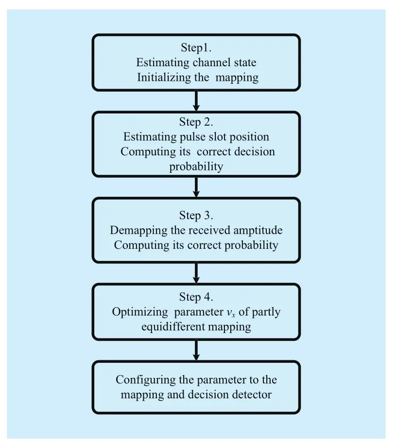
Fig. 2 Optimization of partly equidifferent mapping parameter
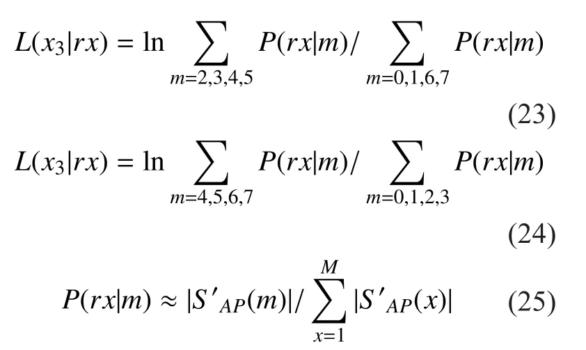
On the other hand, the LLRs of pulse amplitude mapping bits x1and x2, can be deduced according to the time slot which gets the maximum level. Notice that “N” successively takes a value from the set of mapping amplitude{0.36, 1.57, 2.78, 4} in the following formulas.
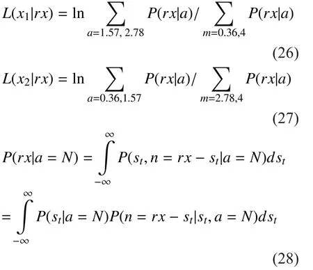
In strong turbulence condition, the intensity fluctuation of transmitting optical signal obeys negative exponential distribution. The posterior probability is considered to be calculated as follows:
IV. LDPC CODING AND DECODING
LDPC coding is the most popular FEC approach in recent years. It present excellent BER performance as well as relatively low decoding complexity in traditional optical fiber and wireless communication systems [17-23].But it also needs proof for FSO conditions.Here a LDPC coding and decoding is adopted to enhance the BER performance of GDAPPM FSO system and its basic principle are mentioned as follows.
The general coding method of LDPC includes three steps. Firstly, bit stream of message source is shaped into 1×j row vectors δi, where j equals the column number of generator matrix G which can be obtained by transforming parity check matrix H. Finally the shaped vectors δican be encoded into coded bits δenby matrix multiplication δen=δi×G.Based on LLRs computed following the procedures described in section 3.2, a 5-procedure LLR-BP algorithm is described as follows.
1. Initialization for variable node vml(calibration equation indexes of each calibration equation), information node qmltransmitting to check nodes uml(variable indexes of each calibration equation) and the maximum iterating times kiter:

2. The horizontal step: check nodes umlupdating as

3. The vertical step for variable nodes vmlupdating as

4. The posterior probability vlupdating as

5. Bit decision: If vl>0, the bit decision is 0. Otherwise the bit decision 1 is made. Asiteration index up to kitertimes,make final bit decision as the decoding result,otherwise begin the next iteration from the second procedure.
V. SYSTEM SIMULATION
After analyzing the channel model, Modula-tion and Forward Error Correction, The whole structure of the LDPC-GDAPPM FSO system is presented in Figure 3. As is designed above,the binary source, encoder, GDAPPM mapper,optical modulator and corresponding recovery modules together constructed the entire simulation system. At first, 0-1 distribution source bits δs(n) are generated from a signal source module, then a conventional LDPC encoder encodes the bit stream into LDPC coded bits δm(n). The GDAPPM mapper makes δm(n) to be a differential baseband symbols SGDAPPM(n)which have a certain pulse amplitude among the novel amplitude set {0,v,v+d,v+2d,v+3d,4}according to section III. Then the baseband symbols SGDAPPM(n) are finally shaped as SGDAP-PM(t) and modulated by an optical modulator,thus complete the entire transmit process. In strong turbulence channel and optical receiver,each signal Sf(t) is affected by a negative exponential fading and additive white Gaussian noise. At the receive terminal, the receiver recovers the frequency-band signal into the baseband signal. Consequently it is demapped to LLRs outputs. At last, the LDPC decoder calculated the final result of received bitstream which be checked with transmitted bits for BER calculation. A comparable group without LDPC coding is also simulated for comparative analysis of BER improvement.
Some important parameters are initialized as follows: Eb/N0varies from 12 ~ 24dB,=5×10-14, L=2km, k=2×10⁶π/1.55, N0=2σ2, then LDPC decod- ing iteration number limit kitaking value 10. Results of 4×4 and 4×8 GDAPPM (denoted by A×M DAPPM-Novel and A×M DAPPM-LDPC 10 interation-Novel) in strong turbulence condition are shown in Figure 4 and Figure 5 respectively.
Significant BER improvement is achieved by using the proposed scheme in both GDAPPM and LDPC-GDAPPM. Comparing with classical LDPC-DAPPM, the LDPC-GDAPPM in strong turbulence achieved 2 dB coding gain approximately. In the new systems, BER come down to 0.5×10⁻⁶~10-6. While compared with the uncoded 4×4 DAPPM, the LDPC-GDAPPM scheme can provide about 5 dB maximum coding gain at the BER of 10-2. As for the 4×8 LDPC-GDAPPM, leveraging the coding gain its BER improvement still achieve 1 dB compared with classical coded DAPPM,even though more pulse position increase misjudgment probability of low amplitude pulse in strong turbulent channel.
VI. CONCLUSION
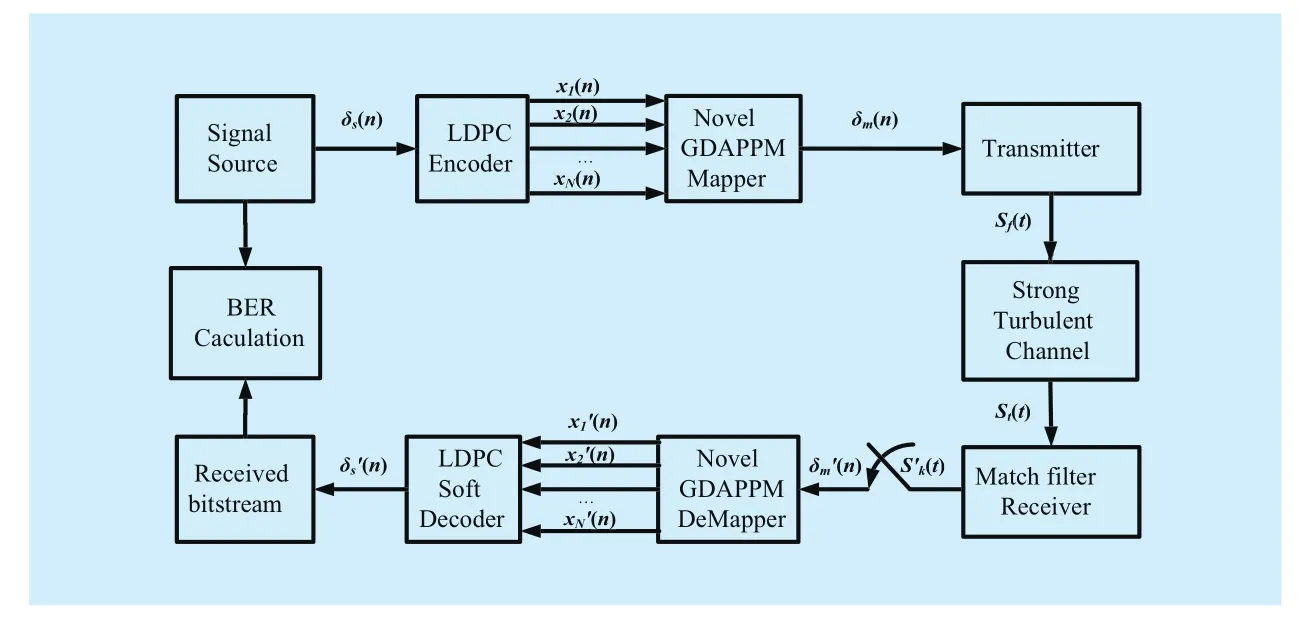
Fig. 3 Simulation system of LDPC-GDAPPM FSO
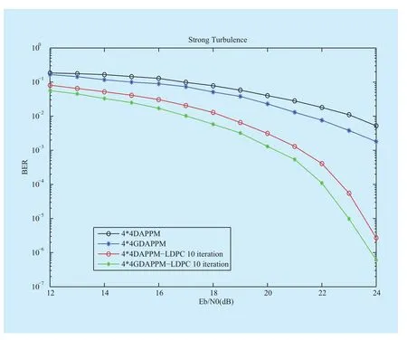
Fig. 4 BER performance of 4×4 GDAPPM in strong turbulence
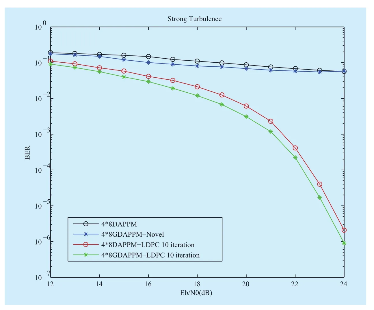
Fig. 5 BER performance of 4×8 GDAPPM in strong turbulence
To sum up, a novel DAPPM FSO as well as LDPC-GDAPPM is proposed, and its efficiency and reliability are demonstrated in turbulent channel. The novel scheme mainly composed of partly equidifferent mapping and its demodulation. Simulation results show about 2dB transmit power reduction against traditional 4×4 DAPPM at the identical BER. This novel scheme contributes to saving optical transmission power to achieve the same BER performance, so it is a “green” approach. To scale up the proposed partly equidifferent mapping approach for other turbulent FSO system, we will further investigate the region based statistical channel model and advanced forward error control schemes in our future work.
ACKNOWLEDGEMENTS
This work was partially supported by the National High-tech R&D Program (863 Program) 2013AA041003, the Natural Science Foundation of China under Grants 51165033,and the Science and Technology Department of Jiangxi Province of China under grant 20151BBE50046, 20142BBE50035 and 20151BAB207052.
[1] WANG Kaimin, Bo L, Lijia Z, et al, “Review of coded modulation free space optical communication system”[J],China Communications,vol.12, no.11, pp 1-17, 2015.
[2] PATNAIK B, SAHU P K, “Design and study of high bit–rate free–space optical communication system employing QPSK modulation”[J].International Journal of Signal and Imaging Systems Engineering, vol.6, no.1, pp 3-8. 2013.
[3] LEE S H, JUNG S Y, KWON J K. “Modulation and coding for dimmable visible light communication”[J].IEEE Communications Magazinevol.53,no.2, pp 136-143,2015.
[4] AMINIAN M S, DONG Y, “Routing in Terrestrial Free Space Optical Ad-Hoc Networks”[D]. PhD thesis, Linköping University Institute of Technology, Norrköping, 2014.
[5] KHAN M, YUKSEL M, “Maintaining a free-space-optical communication link between two autonomous mobiles”[C]// Proceedings of IEEE Wireless Communications and Networking Conference (WCNC). Isanbul, Turkey:IEEE Press,pp 3154-3159, 2014.
[6] UBOLTHIP SETHAKASET, T. AARON GULLIVER,“Differential Amplitude Pulse-Position Modulation for Indoor Wireless Optical Communications”[J].EURASIP Journal on Applied Signal Processing, no.1, pp 3–11, 2005.
[7] POOJA GOPAL, V.K.JAIN, SUBRAT KAR, “Performance Analysis of Ground to Satellite FSO System with DAPPM Scheme in Weak Atmospheric Turbulence”[C]// Proceedings of International Conference on Fiber Optics and Photonics(PHOTONICS). Chennai, India:OSA Press. pp 1–6, 2012.
[8] ZHANG Zhengya, VENKAT ANANTHARAM, MARTIN J. WAINWRIGHT, “An Efficient 10GBASE-T Ethernet LDPC Decoder Design With Low Error Floors”[J].IEEE Journal of Solid-State Circuits, vol.45, no.4, pp 843-855, 2010.
[9] ZHENG Dou, SHA Xuejun, “LDPC-Coded Optical PPM Communication System over the Atmosphere Turbulence Channels”[C]// Proceedings of Information and Automation (ICIA). Harbin,China :IEEE Press, pp 2277-2280, 2010.
[10] IVAN B. DJORDJEVIC, “LDPC-coded MIMO optical communication over the atmospheric turbulence channel using Q-ary pulse-position modulation”[J].Optics express, vol.15, no.16, pp 10026-10031, 2007.
[11] WANG K, ZHANG Q, WANG Y, et al. “LDPC-coded A×M-DAPPM systems for simulation of turbulent free-space optical communication system”[C]// Proceedings of 12th International Conference on Optical Communications and Networks (ICOCN). Chengdu, China:IEEE Press,pp 120-126, 2013.
[12] EPPLE B. “Simplified Channel Model for Simulation of Free-Space Optical Communications”[J].IEEE/OSA Journal of Optical Communications and Networking, vol.5, no.2, pp 293-304, 2010.
[13] DAVASLIOĞLU K, ÇAĞIRAL E, KOCA M. “Free space optical ultra-wideband communications over atmospheric turbulence channels”[J].Optics express, vol.18, no.16, pp 16618-16627,2010.
- China Communications的其它文章
- Direction of Arrivals Estimation for Correlated Broadband Radio Signals by MVDR Algorithm Using Wavelet
- Signal Path Reckoning Localization Method in Multipath Environment
- Adaptive Application Offloading Decision and Transmission Scheduling for Mobile Cloud Computing
- Degree-Based Probabilistic Caching in Content-Centric Networking
- Efficient XML Query and Update Processing Using A Novel Prime-Based Middle Fraction Labeling Scheme
- Smart Service System(SSS): A Novel Architecture Enabling Coordination of Heterogeneous Networking Technologies and Devices for Internet of Things

