火电厂汽轮机叶片开裂原因分析
黎 华, 卢忠铭, 刘课秀, 王 恋(广州特种承压设备检测研究院, 广州 510663)

火电厂汽轮机叶片开裂原因分析
黎 华, 卢忠铭, 刘课秀, 王 恋
(广州特种承压设备检测研究院, 广州 510663)
某火电厂汽轮机末级动叶片在停机检修时发现端部进汽侧背弧面上存在一段裂纹,运用宏观观察、化学成分分析、硬度测试、金相检验、断口扫描及能谱分析等方法,对汽轮机叶片的开裂原因进行了分析。结果表明:汽轮机末级动叶片上的裂纹形成于进汽侧背弧面上的水蚀坑处,动叶片承受的拉应力以及氯离子腐蚀的工作环境,导致叶片发生了晶间应力腐蚀开裂。
汽轮机叶片;开裂;氯离子;应力腐蚀开裂
某火力发电厂汽轮机停机检修时发现多个末级动叶片开裂现象,该汽轮机组仅投入运行6 a(年),累计运行约36 000 h,只达到理论设计寿命的一半[1-5]。汽轮机采用一次中间再热循环,三缸双排汽抽汽凝汽式结构,高压缸进汽参数为16.7 MPa/537 ℃,低压缸进汽参数为1.5 MPa/537 ℃,转速3 000 r·min-1,额定功率300 MW。为了查明该汽轮机叶片开裂的原因,对叶片进行了一系列理化检验和分析,以避免类似失效事件的再发生。
1 理化检验
1.1 宏观观察
汽轮机开裂叶片的宏观形貌如图1所示,开裂叶片为汽轮机正向末级叶片中的35号叶片,开裂均发生于叶片端部,裂口较直且断面与叶片主轴方向基本垂直,未见明显塑性变形,具有脆性开裂特征。叶片进汽侧光滑无腐蚀现象,而背弧面边缘上存在锯齿状水蚀现象。图2所示为图1中汽轮机叶片①,②开裂部位经人工打开的断口形貌。
为进一步分析开裂原因,按图1~2所示对开裂叶片取样进行化学成分分析、冲击试验、硬度试验、金相检验、断口表面扫描电镜及能谱分析。
1.2 化学成分分析
汽轮机叶片材料为1Cr12Ni3Mo2VN钢,对开裂叶片图1(a)中①,③位置取样进行化学成分分析,试验温度为22 ℃,结果表明叶片的化学成分符合产品质量保证书的规定,见表1。

表1 开裂叶片化学成分分析结果(质量分数)Tab.1 Analysis results of chemical compositions of the cracking blade (mass fraction) %

图1 汽轮机开裂叶片的宏观形貌Fig.1 Macro morphology of the cracking turbine blade:(a) intake side; (b) extrados

图2 汽轮机开裂叶片裂口横截面形貌Fig.2 Fracture morphology of the cross section of the cracking turbine blade
1.3 冲击试验
对开裂叶片图1(a)中④,⑤,⑥位置纵向取样进行冲击试验,结果表明叶片的冲击吸收能量符合产品质量保证书的规定,见表2。

表2 开裂叶片冲击性能试验结果Tab.2 Testing results of the impact property of the cracking blade
1.4 硬度测试
对图2中裂口②位置毗邻部位的横截面进行了硬度测试,测试位置见图3,每个测点间隔2 mm,结果表明叶片硬度的测试结果符合产品质量保证书的规定,见表3。

图3 硬度测试位置示意图Fig.3 Schematic diagram of the hardness testing positions
1.5 金相检验
为了了解叶片显微组织及裂纹扩展情况,在开裂叶片图1(a)中位置②,③的横截面取样进行金相检验。结果显示叶片的显微组织均为保持马氏体位相的回火索氏体,叶片边缘处的细小裂纹均起源于边缘水蚀形成的坑洞中,纵深扩展基本与叶片主轴方向垂直,且存在树枝状分叉裂纹,见图4(a)~(b);裂纹沿晶扩展,见图4(c)~(d),毗邻开裂部位边缘的显微组织中可见碳化物沿晶界聚集,见图4(e),远离开裂部位的母材组织未见异常,见图4(f)。
1.6 扫描电镜及能谱分析
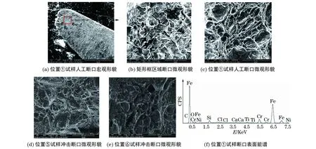
对图1(a)中位置①裂口、位置⑤,⑥冲击断口等进行扫描电镜观察和能谱分析,结果表明裂口断面①背弧面边缘上存在深约1 mm的锯齿状毛刺,断口形貌呈冰糖块状,局部可见核桃纹及泥纹腐蚀花样,晶界处发现二次裂纹,具有典型的沿晶开裂特征,见图5(a)~(b)。人工断口①,⑤,⑥的微观形貌均具有韧窝断裂特征,见图5(c)~(e)。能谱分析结果表明,叶片开裂断口表面除基体金属外,含有一定的氯元素,见图5(f)及表4。

表3 开裂叶片的硬度测试结果Tab.3 Hardness testing results of the cracking blade

图4 开裂叶片各部位显微组织形貌Fig.4 Microstructure morphology of different areas of the cracking blade:(a) cross section at the edge of position ② (without etching); (b) cross section at the edge of position ③ (without etching);(c) cross section at the edge of position ② (after etching); (d) amplified local microstructure;(e) microstructure besides the edge of position ②; (f) microstructure besides the edge of position ③

图5 开裂叶片各部位的扫描电镜形貌及局部区域能谱Fig.5 SEM morphology of different areas and local energy spectrum of the cracking blade:(a) macro morphology of the manual fracture at position ①; (b) micro morphology of the fracture in rectangle area;(c) micro morphology of the artificial fracture of the position ① specimen;(d) micro morphology of the impact fracture of the position ⑤ specimen;(e) micro morphology of the impact fracture of the position ⑥ specimen;(f) energy spectrum of the fracture surface of the position ① specimen

表4 位置①试样断口表面各元素含量(质量分数)Tab.4 Chemical compositions of the fracture surface of the position ① specimen (mass fraction) %
2 分析与讨论
综合理化检验的结果,可知开裂叶片满足产品质量证明书对1Cr12Ni3Mo2VN钢化学成分、冲击吸收能量及硬度的要求,叶片材质合格。
叶片开裂起源于叶片进汽侧背弧面边缘上的水蚀坑内,这是由于该区域更易富集汽水中的杂质溶解物。
根据断口宏观、微观形貌分析,可知裂口无宏观塑性变形,起裂区的微裂纹呈树枝状由边缘向内部扩展。主裂纹与叶片上的离心拉应力垂直,具有应力腐蚀开裂(SCC)的宏观特征。断口微观形貌呈冰糖块状,局部可见核桃纹及泥纹腐蚀花样,具有典型的沿晶开裂特征。
由能谱分析可知,断口表面除含有一定量的氯元素外还有较多的氧元素,而溶液中的溶解氧会加速氯化物应力腐蚀开裂,其阳极溶解模型见图6。

图6 SCC阳极溶解模型示意图Fig.6 Schematic diagram of the anodic dissolution model for SCC
3 结论及建议
汽轮机末级动叶片上的开裂属于氯离子应力腐蚀开裂。动叶片进汽侧背弧面边缘上的冲击磨损蚀坑易于富集各类杂质,当富含溶解氧的汽水中存有氯离子时,在动叶片离心拉应力的作用下,容易导致氯离子应力腐蚀开裂。
为避免汽轮机在之后的正常运行中再次发生此类失效事件,建议采取以下措施。
(1) 防止冷却工业水从凝汽器中泄漏进入锅炉水系统,加强给水质量的监督,提高蒸汽品质,将氯离子含量降到最低。
(2) 保持锅炉洁净,防止蒸汽中微小颗粒冲蚀叶片并发展为裂纹源。
(3) 加强汽轮机的停机保护,保持汽轮机通流部分干燥。
(4) 定期对汽轮机进行开缸检查,特别要加强对叶片进行无损检测,尽早发现开裂问题。
[1] 徐灏.机械设计手册第一卷:机械设计[M].北京:机械工业出版社,1991.
[2] 王志奋,张友登,王俊霖,等.汽轮机叶片断裂分析[J].理化检验-物理分册,2013,49 (增刊2):270-273.
[3] 张亚明,夏邦杰,董爱华,等.热电厂汽轮机叶片断裂原因分析[J].腐蚀科学与防护技术,2009,21(6):590-592.
[4] 虞挺.汽轮机叶片断裂分析[J].理化检验-物理分册,2007,43(5):250-256.
[5] 张升才.汽轮机叶片断裂失效分析[J].金属热处理,2006,31(10):79-81.
Analysis on Fracture Reasons of Turbine Blades in a Heat-power Plant
LI Hua, LU Zhong-ming, LIU Ke-xiu, WANG Lian
(Guangzhou Special Pressure Equipment Inspection & Research Institute, Guangzhou 510663, China)
The last stage moving blades of a generators turbine in a heat-power plant were found cracking on extrados at the end of the steam admission side during maintenance downtime. The cracking reasons of the turbine blades were analyzed by macroscopic observation, chemical composition analysis, hardness testing, metallographic examination, fracture scanning and energy spectrum analysis. The results show that: the origin of the cracks was located in the water-eroded pits on the extrados surface of steam admission side of the last stage turbine blades; the intergranular stress corrosion cracking was caused by tensile stress of moving blades and the working environment of chloride ion corrosion.
turbine blade; cracking; chloride ion; stress corrosion cracking
2016-06-02
黎 华(1964-),男,教授级高级工程师,硕士,主要从事特种设备检验研究工作,gzlihua@163.com。
10.11973/lhjy-wl201703011
TG172.5
B
1001-4012(2017)03-0197-04

