Computational design of iris folding patterns
Yuki Igarashi(),Takeo Igarashi,and Jun Mitani
Research Article
Computational design of iris folding patterns
Yuki Igarashi1(),Takeo Igarashi2,and Jun Mitani3
Iris folding is an art-form consisting of layered strips of paper,forming a spiral pattern behind an aperture,which can be used to make cards and gift tags.This paper describes an interactive computational tool to assist in the design and construction of original iris folding patterns.The design of iris folding patterns is formulated as the calculation of a circumscribed polygonal sequence around a seed polygon.While it is possible to compute the positions of vertices analytically for a regular polygon,it is not straightforward to do so for irregular polygons.We give a numerical method for irregular polygons,which can be applied to arbitrary convex seed polygons.The user can quickly experiment with various patterns using the system prior to constructing the art-form.
craft;pattern;fabrication;user interface;novice users
1 Introduction
Iris folding is an art-form consisting of layered paper strips that form a spiral pattern behind an aperture, as shown in Fig.1.Iris folding is a simple and fun paper-folding technique that can be used to make greeting cards and gift tags.The design forms an irislike pinhole at the center,similar to that of an eye or a camera lens.In a typical workflow,a person first prepares a guide sheet(usually taken from a book), base sheet,and paper strips.She then cuts the base sheet making a hole as shown in the guide sheet.She places the base sheet on the guide sheet and pastesthe paper strips on the base sheet following the instructions shown in the guide sheet.After pasting all the paper strips,she turns the base sheet over to obtain the final result.
1 Meiji University,Nakano-ku,164-8525,Japan.E-mail: yukim@acm.org().
2 The University of Tokyo,Bunkyo-ku,113-0033,Japan. E-mail:takeo@acm.org.
3 University of Tsukuba,Tsukuba-city,305-8573,Japan. E-mail:mitani@cs.tsukuba.ac.jp.
Manuscript received:2016-08-27;accepted:2016-09-23
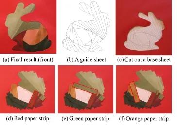
Fig.1 (a)The end result viewed from the front.(b)A guide sheet.(c)–(f)The construction process viewed from the back.(c) The user first cuts out some paper and turns it over onto a guide sheet.(d)–(f)The user then pastes colored paper strips around the central polygon.
There are several interesting geometric properties of iris folding patterns,which make the design of such patterns an intriguing mathematical problem. Although it can be easy to design basic iris folding patterns,even for novices,many of the more complex geometrical patterns must satisfy certain geometric constraints,as shown in Fig.2.It is typically difficult for novices to design such patterns.If the geometric constraints are not satisfied,paper is wasted because the design does not effectively use the width of the paper strips.In addition,manual construction takes more time as the number of required polygons increases.
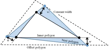
Fig.2 Problem:calculate the next polygon circumscribing the inner polygon such that the distance from the vertices of the polygon to the corresponding internal polygon edge is constant.
This paper presents an interactive computational system to assist in the design and construction of original iris folding patterns that satisfy geometric constraints.Figure 3 shows an overview of the process.The user first inputs an outline and a seed polygon inside it.The system then automatically computes an iris folding pattern,i.e.,a series of strips around the seed polygon.The user can experiment with arbitrary polygons and color combinations prior to completing the pattern.
The design of iris folding patterns requires the computation of a series of strips of equal width around the polygon.As shown in Fig.2,we formulate this design problem as the calculation of an offset polygonal sequence around an inner polygon, satisfying the constraint that the distance from the vertices of the polygon to the corresponding internal edge of the polygon must be constant(i.e.,the width of the paper strips is constant).In this manner, the system computes iris folding patterns around an arbitrary convex seed polygon.
2 Related work
Various interesting systems have been proposed recently to support the fabrication of physical objects using state-of-the-art graphics techniques. Mitani and Suzuki[1]presented a system for paper craft. Li et al.[2,3]presented systems for popup cards.
As for two-dimensional objects,Coahranm and Fiume[4]reported a sketch-based design system for a specific quilting art-form,Bargello patterns. They described an algorithm that transforms sketched input data into graceful Bargello curves. Holly[5]is an interactive stencil design system for novices,providing a method for generating expressive stencils, where a user simply uses standard drawing operations and the system automatically generates the appropriate stencil satisfying constraints.Patchy[6]is an interactive system that can assist in the design of original patchwork patterns.The user designs original patchwork strokes,and can quickly experiment with various patterns prior to sewing.
The pursuit curve of a polygon forms a geometric pattern similar to iris folding.It is defined as the trajectories of vertices starting from the corners of the polygon,and moving inwards pursuing the neighboring vertices[7].In the case of a triangle, three pursuit curves converge to a point known as the Brocard point.Although pursuit curves form similar patterns to those seen in iris folding,the definitions differ,and the analysis of pursuit curves cannot be applied directly to our problem.
3 User interface
Figure 3 shows an overview of the process.The user first inputs an outline and a seed polygon,as shown in Fig.3(a).Then it automatically computes an iris folding pattern(Fig.3(b)).The user can experiment with arbitrary polygons and color combinations prior to completing the pattern.The user can also apply textured rendering as shown in Fig.3(c).The user finally creates the physical pattern(Fig.3(d)).

Fig.3 Overview of our system.(a)The user first inputs an outline S(blue line)and a seed polygon P(black line).(b)Then the system automatically computes a pattern for iris folding and(c)applies texture rendering.(d)The user finally creates the physical pattern.
3.1 User inputs
The user first inputs an outline polygon S and an internal convex seed polygon P inside S.The user can change the width w of the paper strips.The system provides two methods to input the outline S: the user can either draw a stroked line directly,or can load a black-and-white bitmap image and have the system trace the contour line using the marchingsquares algorithm[8].
The user draws a polygon P,as shown in Fig.3(a). Arbitrary polygons can be designed by clicking on desried vertex positions for the polygon.The user can also draw a regular polygon by choosing one from a menu.The system automatically places the polygon at the center,and the user can drag it to a desired position.It is also possible to scale the polygon P.The default width of the paper strips is 10 mm;however,this can be changed using the menu.The user can change the orientation of the strips using the menu.
3.2 Interactive design
Once the outline S,the seed polygon P,and the strip width w have been determined,the system automatically generates a pattern for iris folding.If the user drags the vertices of the internal polygon P,the system updates the pattern in real time.The user can set the colors of the strips using a paint tool. By default,the system shows a design with n-sided polygons with n colors:see Fig.3(b).
To create a shaded image,the system may also switch to visualization with shading,considering the layers of paper strips,as shown in Fig.4.Regions of the same color are grouped for previewing,and the system calculates a rendered image for each group.The user can preview the resulting image using a textured image of paper strips.It cannot be manipulated interactively while previewing the texture image,however,and the system switches to normal coloring mode whenever the user performs a dragging operation(Fig.5).

Fig.4 The fill tool(left)and textured rendering(right).
3.3 Construction guide
The system ultimately outputs a pattern for use in construction.The user pastes paper strips onto the back of the main piece of paper,as shown in Fig.6.Therefore,the resulting guide sheet is flipped horizontally.The system also shows a step-by-step graphical presentation to aid the construction.
4 Theoretical analysis
This section provides a theoretical analysis of the geometric problem.The algorithm used in the current implementation is described in the next section.First we define the problem,and then we analyze regular seed polygons,followed by irregular seed polygons.
4.1 Definitions
The seed polygon P(input by the user)is defined as P0.The polygons formed using paper strips are defined as Pm(m=1,2,...). We consider the problem as determining Pm+1from Pmfor a given strip width w.The system first computes an offset polygon Pm',i.e.,the polygon that is obtained by offsetting each edge of Pmby the strip width w.
Then it searches for the Pm+1that satisfies the following geometric constraints:(i)the vertices of the next polygon Pm+1should be located on the edge of the offset polygon Pm',and(ii)the edges of the next polygon Pm+1should pass through the vertices of the polygon Pm.
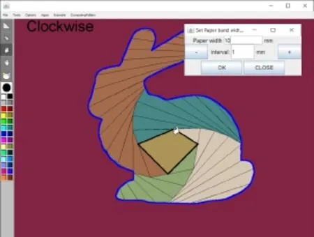
Fig.5 Screen capture of our system.The user can interactively change the design by dragging the seed polygon.

Fig.6 A step-by-step construction guide.
4.2 Analytical solutions for regular polygons For a regular n-gon(n-sided polygon)Pm,it is possible to analytically calculate the angle of rotation and the scaling ratio that maintain the next polygon Pm+1as an n-gon.As shown in Fig.6,for an internal angle of the n-gon α and strip width w,the edge length l can be found.The system computes the angle of rotation θ whereby the vertices of the polygon Pm+1lie on the edges of the strip.
The geometrical relations shown in Fig.7 can be expressed as follows:

Eq.(1)can be rewritten as
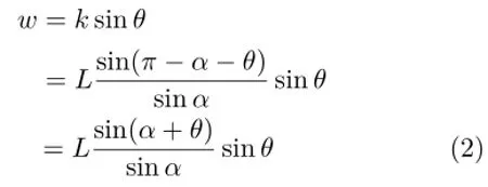
When L=1,we obtain the angle of rotation θ as follows:


Fig.7 Iris folding geometry for a regular n-polygon.
4.3 Numerical analysis for arbitrary polygons
Now we describe a numerical approach for an arbitrary n-gon Pm.As shown in Fig.8,the vertices of an n-gon Pmare defined asin clockwise order.We put a point vstarton the edgeby varying the parameter t in the range[0, 1].The straight line l1passes through vstartand, and intersects the edgeat pointThe straight line that passes throughandis lineli+1,which intersects the edge betwee natThe straight line that passes through vstartandis line l0. The point where lines l0and ln-1intersect is v(t).The intersection between the trajectory of v(t)and the edge becomes
Obtaining an explicit formula to compute Pm+1from Pmis overly complicated and difficult. Instead,we analyzed the problem numerically using interactive geometry software(Cinderella[9]).By varying t in the range 0 to 1,the trajectory of v(t) can be found,as shown in Fig.9.We observe that the trajectories are conic curves,and therefore we can calculate the value t for which the point v(t)is located on an edge of Pm'using bisection search. (The Appendix shows that the trajectory is a conic curve,with a quadratic equation,when the seed polygon is a triangle.)
5 Algorithm
We calculate the next polygon Pm+1from polygon Pmusing bisection search.The system computes the signed distance from v(t)to the corresponding edgeIf the user chooses a clockwise pattern, we search for the parameter t between[0,0.5];if the user chooses a counterclockwise pattern,we search
for t between[0.5,1].After finding the value of t, the system generates Pm+1using the value.This is repeated until Pm⊃P(S),where P(S)includes the polygon of the desired outline S.
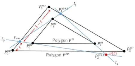
Fig.8 Analysis of iris folding with arbitrary polygons.The aim is to find t such that v(t)is located on the edge
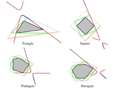
Fig.9 By varying t from 0 to 1 on the pink edge of the offset polygon,the trajectory v(t)is found(red line).v(t)forms a part of a conic curve:for example,by varying t from −100 to 100,the trajectory v(t)was found(blue line).We find the value t for which the point v(t)is located on the orange edge of the offset polygon.
Because the trajectory is a conic curve,a solution does not always exist.The existence of a solution depends on the ratio of the strip width to the edge length of the polygon(see Fig.10).If a solution cannot be found,the system does not draw a pattern, but instead prompts the user to let the system search for another solution by moving some vertex of the internal polygon,or by changing the strip width w. If a solution still cannot be found,the system tells the user so.
6 Results

Fig.10 The existence of a solution depends on the ratio of the strip width to the length of the edges of the polygon.Here the ratio w/l was varied from 0.29 to 0.33,0.37,and 0.41(left to right).For w/l=0.37 and 0.41,a pattern could not be formed.
A prototype of the system was implemented in Java running on a laptop computer with a 1.2 GHz processor and 2 GB RAM.We used this system to create designs for iris folding patterns, as shown in Fig.11.Users were allowed to experiment with various patterns using the system prior to beginning construction.A design session typically takes approximately 10–20 minutes,and construction takes about 1 hour.
7 Conclusions and future work
We have described an interactive design system for generating iris folding patterns.Users can quickly experiment with various patterns using the system before beginning practical work.
In future,we plan to develop a method to handle multiple internal polygons.We also plan to investigate patterns formed with other constraints, such as symmetry and similarity to the original polygon. We also plan to investigate conditions for the existence of a polygon which circumscribes a polygon and inscribes a polygon. It is also an interesting problem to analyze the requirements concerning the shape of the internal polygon and the upper limit of the ratio of the strip width to the edge length of the polygon for a given shape.We also plan to consider how the system may determine
which vertices it makes sense for the user to modify, and in which direction it should move,to guide the user to a feasible solution when an error occurs.
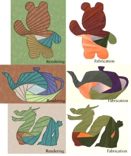
Fig.11 Design examples created using our system.
Appendix
In this appendix,we show that the trajectory of Q is a conic curve(quadratic equation)when the seed polygon is a triangle.
The vertices of a polygon Pmare defined as,in clockwise order,as shown in Fig.12.The system first computes an offset polygon Pm',i.e.,the polygon that is obtained by offsetting each edge of Pmby the strip width w.We put a pointon the edgeThe straight line l1passes throughand,and intersects the edgeat point. The straight line l2passes throughand.The straight line that passes throughandis line l0.The point where lines l0and l2intersect is.The intersection between trajectory ofand the edgebecomes

In the following derivation,each occurrence of C represents a different constant value.
We have five constraints as follows:


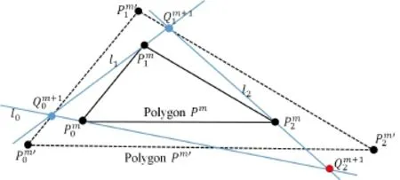
Fig.12 Inner polygon Pmis given(input)and we observe how(x2,y2)moves as we move(x0,y0)on.


We have six unknown values(x0,y0),(x1,y1), (x2,y2).We wish to get an expression relating x2and y2by eliminating the variables(x0,y0)and(x1,y1). Constraint(4)can be rewritten as

Constraint(5)can be rewritten as

Constraint(6)can be rewritten as
(x0-X0)(y2-Y0)=(y0-Y0)(x2-X0) (11)
Constraint(7)can be rewritten as
(x1-X1)(y0-Y1)=(y1-Y1)(x0-X2) (12)
Constraint(8)can be rewritten as
(x1-X2)(y2-Y2)=(y1-Y2)(x2-X2) (13)
To eliminate y0and y1,substitute Eqs.(9)and (10)into Eq.(11):
(x0-X0)(y2-Y0)=(C x0+C)(x2-X0) (14)
To eliminate y0and y1,substitute Eqs.(9)and (10)into Eq.(12):
(x0-X1)(C x0+C)=(C x1+C)(x0-X1)(15)
To eliminate y0and y1,substitute Eqs.(9)and (10)into Eq.(13):
(x1-X2)(y2-Y2)=(C x1+C)(x2-X2) (16)
Eq.(14)can be rewritten as

Eq.(16)can be rewritten as

To eliminate x0and x1we substitute Eqs.(17)and (18)into Eq.(14).We first rewrite Eq.(15)as
C x0x1+C x0+C x1+C=0 (19)
Eq.(17)can be rewritten as

Eq.(18)can be rewritten as

(a,b,c,d are linear combinations of x2and y2: a(x2,y2)=C x2+C y2+C).
We substitute Eqs.(20)and(21)into Eq.(19), then multiply both sides by b(x2,y2)d(x2,y2).
C a(x2,y2)c(x2,y2)+C a(x2,y2)d(x2,y2) +C c(x2,y2)b(x2,y2)+C b(x2,y2)d(x2,y2)=0
This shows that the trajectory is a conic curve (quadratic equation in x2and y2)because all terms mutliply a linear combination of x2and y2by a linear combination of x2and y2.
Acknowledgements
We thank Kazushi Ahara for his comments.We also thank Takuya Sawada for his help in writing the paper. This work was supported in part by JSPS KAKENHI Grant Number 26240027.
Electronic Supplementary Material Supplementary material is available in the online version of this article at http://dx.doi.org/10.1007/s41095-016-0062-4.
[1]Mitani,J.;Suzuki,H.Making papercraft toys from meshes using strip-based approximate unfolding.ACM Transactions on Graphics Vol.23,No.3,259–263, 2004.
[2]Li,X.-Y.;Shen,C.-H.;Huang,S.-S.;Ju,T.;Hu,S.-M.Popup:Automatic paper architectures from 3D models.ACM Transactions on Graphics Vol.29,No. 4,Article No.111,2010.
[3]Li,X.-Y.;Ju,T.;Gu,Y.;Hu,S.-M.A geometric study of v-style pop-ups:Theories and algorithms.ACM Transactions on Graphics Vol.30,No.4,Article No. 98,2011.
[4]Coahranm,M.;Fiume,E.Sketch-based design for Bargello quilts.In: Proceedings of Eurographics Workshop on Sketch-Based Interfaces and Modeling, 165–174,2005.
[5]Igarashi,Y.;Igarashi,T.Holly:A drawing editor for designing stencils.IEEE Computer Graphics and Applications Vol.30,No.4,8–14,2010.
[6]Igarashi,Y.;Mitani,J.Patchy: An interactive patchwork design system.In:Proceedings of ACM SIGGRAPH 2015 Posters,Article No.10,2015.
[7]Peterson,I.Pursuing pursuit curves.2001.Available at https://www.sciencenews.org/article/pursuingpursuit-curves.
[8]Lorensen,W.E.;Cline,H.E.Marching cubes:A highresolution 3D surface construction algorithm.ACM SIGGRAPH Computer Graphics Vol.21,No.4,163–169,1987.
[9]Cinderella.The interactive geometry software.1998. Available at http://cinderella.de/.

Yuki Igarashi is a senior assistant professor in interdisciplinary mathematical science at Meiji University. She received her Ph.D. degree from the Department of Engineering at the University of Tokyo in 2010.From 2010 to 2015,she was a JSPS research fellow at University of Tsukuba.Her research interests are in computer graphics and user interfaces.
Takeo Igarashi is a professor in the CS Department at the University of Tokyo. He received his Ph.D.degree from the Department of Information Engineering at the University of Tokyo in 2000.His research interest is in user interfaces in general and his current focus is on interaction techniques for 3D graphics. He is known as the inventor of the sketch-based modeling system called Teddy,and received the Significant New Researcher Award at SIGGRAPH 2006.

Jun Mitani is a professor at the University of Tsukuba.He received his Ph.D.degree in engineering from the University of Tokyo in 2004. He has been a professor at the University of Tsukuba since April 2015.His research interests are centered on computer graphics,especially geometric modeling techniques.He studies the geometry of curved origami as well as interactive design interfaces.
Open Access The articles published in this journal are distributed under the terms of the Creative Commons Attribution 4.0 International License(http:// creativecommons.org/licenses/by/4.0/), which permits unrestricted use,distribution,and reproduction in any medium,provided you give appropriate credit to the original author(s)and the source,provide a link to the Creative Commons license,and indicate if changes were made.
Other papers from this open access journal are available free of charge from http://www.springer.com/journal/41095. To submit a manuscript,please go to https://www. editorialmanager.com/cvmj.
© The Author(s)2016.This article is published with open access at Springerlink.com
 Computational Visual Media2016年4期
- Computational Visual Media的其它文章
- LSTM-in-LSTM for generating long descriptions of images
- Texture image classification with discriminative neural networks
- Weighted average integration of sparse representation and collaborative representation for robust face recognition
- Modified filtered importance sampling for virtual spherical Gaussian lights
- A computational model of topological and geometric recovery for visual curve completion
- User controllable anisotropic shape distribution on 3D meshes
