User controllable anisotropic shape distribution on 3D meshes
Xiaoning Wang,Tien Hung Le,Xiang Ying,Qian Sun(),and Ying He
Research Article
User controllable anisotropic shape distribution on 3D meshes
Xiaoning Wang1,§,Tien Hung Le1,§,Xiang Ying1,Qian Sun1(),and Ying He1
This paper presents an automatic method for computing an anisotropic 2D shape distribution on an arbitrary 2-manifold mesh.Our method allows the user to specify the direction as well as the density of the distribution. Using a pre-computed lookup table,our method can efficiently detect collision among the shapes to be distributed on the 3D mesh. In contrast to existing approaches,which usually assume the 2D objects are isotropic and have simple geometry, our method works for complex 2D objects and can guarantee the distribution is conflict-free,which is a critical constraint in many applications. It is able to compute multi-class shape distributions in parallel. Our method does not require global parameterization of the input 3D mesh. Instead,it computes local parameterizations on the fly using geodesic polar coordinates. Thanks to a recent breakthrough in geodesic computation,the local parameterization can be computed at low cost.As a result,our method can be applied to models with complicated geometry and topology.Experimental results on a wide range of 3D models and 2D anisotropic shapes demonstrate the good performance and effectiveness of our method.
shape distribution;anisotropic sampling;discrete geodesics;intrinsic algorithm;parallel computing
1 Introduction
Sampling has a wide range of applications in computer graphics,such as geometry processing, texturing,and rendering.Among many samplingtechniques,blue noise is popular due to its excellent spatial and spectrum properties.In the past decade,many elegant blue noise sampling algorithms have been proposed.Representative works include parallel sampling [1], maximal sampling[2,3],multi-class sampling[4],and bilateral sampling[5].Some algorithms like Refs.[6,7]can also be directly extended from Euclidean space to curved surfaces.However,most existing approaches compute isotropic sample distributions meeting certain constraints,such as efficiency,spectral properties,maximal distribution,and so on.To date, little research effort has been reported for anisotropic sampling on 3D models.
1 School of Computer Science and Engineering, Nanyang Technological University,Singapore.E-mail: zhujianzhai@gmail.com().
§ These authors contributed equally to this work.
Manuscript received:2016-05-03;accepted:2016-07-19

Fig.1 Given a 3D triangle mesh M and a set of 2D anisotropic shapes,the user first specifies a vector field for directional control (top-right inset)and a scalar field for density control(bottom-left inset).Our method then automatically distributes the given 2D shapes onto M,satisfying the user-specified direction and density constraints.It took only 2.9 s to distribute 4 classes of objects on this 400K-face Fertility model.Timing was measured on a 2.66 GHz quad-core CPU.
Li et al.[8]pioneered anisotropic blue noise sampling by extending dart throwing and relaxation for isotropic setting to anisotropic setting.To evaluate sample distribution quality,they proposed uniform-isotropic reversible warping for the plane case and spherical harmonics for the spherical domain. Aided by global parameterization,their
algorithm can also be applied to 3D surfaces. However,it has two limitations that could limit usage in real-world applications. Firstly, the traditional global parameterization computation is a sequential process in nature. Although parallelization techniques (such as the phase grouping method[1])could improve its performance, implementation can be difficult,since anisotropy poses a challenge when performing sampling domain partitioning. Secondly,their method is mainly designed for the Euclidean plane R2and sphere S2, for which parameterizations are readily available. Although it can be applied to 3D surfaces with global parameterization,computing a high-quality parameterization(i.e.,with low angle and/or area distortion)for surfaces with complicated geometry and arbitrary topology is non-trivial.
This paper proposes a practical parallel method for computing a distribution of anisotropic shapes on an arbitrary manifold mesh.Given a 3D model M and a set of 2D anisotropic shapes,the user specifies the desired distribution density as well as the orientation of each class.Our algorithm then automatically distributes the given 2D objects on M,satisfying the density and direction constraints.Unlike existing approaches,which usually assume the 2D objects are isotropic and have simple geometry, our algorithm works for complex 2D objects and can guarantee the distribution is conflict-free,which is a critical constraint in many applications.Moreover, our method does not require a global surface parameterization of the input 3D model.Instead, it computes local parameterizations on the fly using geodesic polar coordinates.Thanks to a recent breakthrough in geodesic computation,local parameterizations can be computed at low cost. Furthermore,our method has a natural parallel structure,and it is also intrinsic in that it depends only on the mesh metric instead of the embedding space.We have evaluated our algorithm on realworld models with non-trivial topology and observed promising results.
The rest of the paper is organized as follows. Section 2 reviews related work on sampling,shape distribution,and discrete geodesics. Section 3 explains how to efficiently computate discrete geodesics and geodesic polar coordinates,and is followed by our parallel algorithm for anisotropic shape distribution in Section 4. Section 5 shows experimental results and discusses the merits and limitations of our method.Finally,Section 6 concludes the paper.
2 Related work
2.1 Sampling
Many recent methods proposed for blue noise sampling on arbitrary surfaces involve dart throwing with rejection schemes or optimization procedures. Wei[1]presented a phase group algorithm which subdivides the sample domain into grid cells and draws samples concurrently from multiple cells that are sufficiently far apart to avoid conflicts.Peyrot et al.[9]combined a feature detection technique based on vertex curvature and geodesic-based dart throwing for direct Poisson disk sampling on triangle meshes;this approach can handle sharp features and high genus meshes.Chen et al.[5]presented bilateral blue noise sampling for handling problems with nonspatial features. Quinn et al.[10]introduced a stratified sampling technique for mesh surfaces that gives the user control over both sampling density and anisotropy via a tensor field.Zhong et al.[11] optimized inter-particle Gaussian kernels with an anisotropic smoothing tensor to achieve anisotropic distribution of samples on a polygonal mesh.Multiclass blue noise sampling with continuous settings has been handled by Wei[4]and Chen et al.[12]. Recently,Liang et al.[13]proposed a novel Poisson disk sampling algorithm based on disk packing which achieves a good balance between randomness and uniformity.The sampling process is time consuming since a large number of trials are discarded because of conflicts.Different techniques have been proposed to improve the performance of blue noise sampling, including effective spatial data structures[2,14, 15],use of a kernel density model[16],and tile-based approaches[17–19]. Zhou et al.[20] presented an algorithm for generating different noise patterns according to user-defined spectra.Their algorithm can be easily modified to achieve adaptive performance.
2.2 Surface mosaics
Surface mosaics can be generated by methods for arranging small regular or irregular tiles to
form a pattern.The tiles can be various elements with different materials and geometric topology. Although the problem of synthesizing 2D mosaics has been extensively studied,only a small amount of work has been applied to digital mosaicing on 3D surfaces. Lai et al.[21]presented an energy optimization method for positioning square tiles of equal size on a surface.That approach is extended in Ref.[22]for mosaicing of non-uniform rectangular tiles with size adjusted according to the local curvature of the target surface. Dos Passos and Walter[23]presented the Opus Palladium method to simulate mixed mosaics with both irregular and square tiles.In their method,tiles are represented inside convex Voronoi polygons. Hu et al.[24] presented an optimization-base solution based on continuous tile configuration,combinatorial tile selection,and tile permutation to reduce gaps between neighboring tiles on the target surface.All mosaicing methods above have a restricted range of tiles[21]or require expensive approximation of Voronoi diagrams and local parameterization[22, 23].
2.3 Shape distribution
Distributing 2D objects has a wide range of graphics applications. For example,line segment distributions are used in rendering applications to produce effects such as motion blur,defocus blur,and scattering media[25],while rectangle distributions are used to simulate decorative mosaics[26,27]. Feng et al.[28]generated nonoverlapping ellipses with blue noise characteristic. Sun et al.[25]gave a frequency analysis of line segment sampling,which can be generalized to arbitrary non-point shapes.
In contrast to their 2D counterparts,shape distribution on 3D surfaces remains largely unexplored.Li et al.[29]proposed a dual Poisson disk tiling scheme to distribute features and patterns on an input parameterized surface.Using a global parameterization,Li et al.[8]presented an algorithm to distribute elliptical samples that exhibited anisotropic blue noise properties on 3D surfaces.They evaluated the spectrum of the anisotropic blue noise by warping and sphere sampling.
2.4 Discrete geodesics
Measuring geodesic distances on polyhedral surfaces is a fundamental problem in computer graphics and computational geometry.The classic computational geometry approaches include the MMP algorithm[30],the CH algorithm[31],and their many variants[32–36].These methods are able to compute an exact solution on arbitrary manifold meshes given exact numerical operations.However, they are computationally expensive.Qin et al.[37] proposed an exact geodesic algorithm based on triangle-oriented window propagation which has good performance with O(n2)time complexity. Their window pruning strategies can effectively reduce the running time,but unfortunately,the actual gain is significant only for global geodesic computation. Partial differential equation(PDE) approaches,such as the fast marching method (FMM)[38]and the heat method[39],are efficient and flexible for a wide range of geometric domains, including triangle meshes,point clouds,grids,and volumes. They can also be easily generalized to an anisotropic setting[40].However,they compute only a first-order approximation and the results are sensitive to model tessellation and resolution.
Recently,there has been a trend to investigate precomputation techniques,with the aim of balancing quality and performance.The heat method[39]is a gradient-based approach,which recovers geodesic distances from the normalized gradient of the heat flow.By pre-factoring the Laplacian matrix, both the heat flow and the distance computation can be computed in near-linear time. The heat method works for both meshes and point clouds. However,like FMM,it provides only a first-order approximation.
Xin et al.[41]proposed the geodesic triangle unfolding(GTU)method,which can compute the geodesic distance between arbitrary points(not necessary mesh vertices)in constant time.In the preprocessing stage,it constructs a geodesic Delaunay triangulation for a set of uniformly distributed points.It then pre-computes the geodesic distances between any pair of sample points. Moreover, for each geodesic triangle,it pre-computes all the geodesic distances between any interior vertex and the three corners. The pre-processing step takes O(mn2log n)time and O(m2+n)space, where n and m are the number of vertices and samples,respectively. These pre-computed paths and distances,forming a dense weighted graph,are
then used in the online distance query stage.Given two query points p and q,the GTU method unfolds the corresponding geodesic triangles containing p,q onto R2and then uses the Euclidean distance between their images to approximate the geodesic distance between p and q.The GTU method can answer a geodesic distance query in constant time, since the unfolding process is completely local.Xin et al.observed that the accuracy of the GTU method closely depends on the number of samples m. However,the quadratic space complexity O(m2+n) and the long pre-computation time O(mn2log n) limit the GTU method to small-scale models and/or a small number of samples.
Observing that the discrete geodesic problem has a surprisingly strong local structure due to the existence of saddle vertices,Ying et al.[42]proposed the saddle vertex graph(SVG),a sparse graph which encodes the geodesic information in a triangle mesh. Using the SVG,computing the geodesic distance is equivalent to finding a shortest path on the graph,making real-time computation of high-quality geodesic distances possible.However,the vertices of the saddle vertex graph are mesh vertices,meaning that it cannot compute the geodesic path and/or distance between points which are not in the mesh vertex set.
3 Efficiently computing discrete geodesic distances between arbitrary points
Both the GTU method and the SVG method are graph-theoretic algorithms: the former forms a dense graph with O(m2+n)edges,where m is the number of samples(specified by user),and the latter forms a sparse graph with O(D n)edges,where
D is a model-dependent-but-resolution-independent constant(D≪n).Each approach has its own merits and limitations. The SVG method can compute highly accurate geodesic distances between any pair of mesh vertices.However,many applications require the distances between arbitrary points of the input mesh.As Fig.2(b)shows,linearly interpolating vertex distances produces poor results on meshes with large and/or irregular triangles,since distance is a non-linear function.On the other hand,the GTU method can efficiently compute the geodesic distance between two arbitrary points in O(1)time. Unfortunately,the price of such a constant-time algorithm is very high memory usage and a long precomputation.
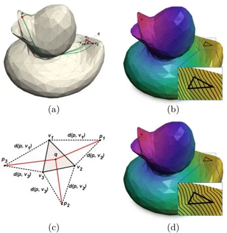
Fig.2 Computing single-source all-destination geodesic distances on a low-resolution mesh.(a)Let p be the source point(a mesh vertex)and q be a point inside the triangle△v1v2v3.(b)Using the saddle vertex graph,we can accurately compute the geodesic distances from p to any mesh vertex.Once geodesic distances are defined on each vertex,we can easily estimate the geodesic distance d(p,q)using linear interpolation.However,the interpolated distances have very low accuracy,since distance is not a linear function.(c) The geodesic triangle unfolding method can significantly improve the accuracy.With known geodesic distances d(p,vi),i=1,2,3,we can unfold the geodesic triangles,△pv1v2,△pv2v3,and△pv3v1onto R2. The geodesic distance d(p,q)is approximately the minimum of the three Euclidean distances d(pi,q),i=1,2,3.(d)Texture mapping shows the high-quality result provided by the GTU method.
In this section,we first show that the SVG and GTU methods can be naturally combined so that we can take advantage of the merits of both and avoid their limitations.We then adopt a label correcting method to improve the performance of shortest path computation in SVG.Finally,we show that the computed geodesic distances induce a high-quality polar coordinate system,which will be used for local parameterization.
3.1 Combination of SVG and GTU
Consider a triangle mesh M=(V,E,F),where V, E,and F are the sets of vertices,edges,and faces, respectively.A vertex v is called a sadd le if the sum of its interior angles exceeds 2π.Mitchell et al.[30] proved that a discrete geodesic path cannot pass through a spherical vertex unless it is an endpoint
or a boundary point,and the unfolded image of the path along any edge sequence is a straight line segment.
The geodesic path γ(vi,vj)between two vertices vi,vj∈V is called direct if it does not pass through any saddle vertices.Otherwise,it can be partitioned into several segments so that each segment is direct. Let Γ={γ(vi,vj)|γ(vi,vj)is direct∀vi,vj∈V} denote the set of all direct geodesic paths on M. Then the saddle vertex graph associated with mesh M is an undirected graph G=(V,Γ).Any existing exact geodesic algorithm,such as the MMP algorithm[30],the ICH algorithm[34],or the most recent FWP-enhanced algorithm[35],can be used to construct the SVG.Ying et al.[42]observed that it is not necessary to compute all direct geodesic paths, and in fact,a small subset of Γ suffices.Therefore, they suggested a simple-yet-effective heuristic to control the SVG size using a parameter K:for a vertex v,only direct geodesic paths within a geodesic disk containing K or fewer vertices are considered. They observed that K∈[50,200]typically produces geodesic distances with relative accuracy 10-4–10-3, which suffices for most applications.
The SVG(V,Γ)allows us to compute the geodesic distance between any pair of mesh vertices. To combine SVG and GTU,we take all mesh vertices as samples,i.e.,m=n.This strategy has three advantages.Firstly,we avoid the need to construct a geodesic triangulation on M,since each f∈F is a geodesic triangle. Secondly,we do not need to explicitly compute and store the entire dense weighted graph for the GTU method,since the SVG method allows us to compute the geodesic distance between any pair of samples(vertices)on the fly. Thirdly,as pointed out by Xin et al.[41],the larger the value of m,the higher the accuracy of the computed geodesic distance.The GTU method achieves best accuracy by setting m=n.
We are now ready to compute the geodesic distance between arbitrary surface points p,q∈M. To ease presentation,we first address the simple case shown in Fig.2 when one point,say p∈V,is a vertex,and the other q/∈V is not.Let△v1v2v3be the triangle containing q.To compute the geodesic distance d(p,q),we first solve the single source, multiple destinations problem on the SVG graph to compute geodesic distances d(p,vi),i=1,2,3. Note that these geodesic distances together with three mesh edges v1v2,v2v3,and v3v1form three geodesic triangles△pv1v2,△pv2v3,and△pv3v1. After unfolding these triangles onto R2,we obtain three images of p,namely,p1,p2,and p3.Finally, the geodesic distance d(p,q)is approximated by the minimum of the three Euclidean distances d(pi,q), i=1,2,3.
The general case p,q/∈V can be solved by unfolding both triangles containing p and q respectively.Readers can refer to Ref.[41]for details.
3.2 Improving performance of the SVG approach
The SVG naturally links the discrete geodesic problem on a polyhedral surface and the shortest path problem on a graph,since computing the geodesic distance between p and q is equivalent to finding a shortest path on the corresponding saddle vertex graph.Dijkstra’s algorithm[43]is widely used for computing shortest paths,so we now review some fundamental concepts of Dijkstra’s algorithm and its improvements.
To compute the shortest paths from a single node, say n1,to all of the other nodes in graph G,Dijkstra’s algorithm maintains a label vector(d1,...,d|V|)and a set of nodes C,called the candidate list,starting with d1=0,di=∞ for i/=1,C={v1}.Dijkstra’s algorithm iteratively processes the nodes from the candidate list C and terminates when C is empty. Upon termination,each label diis the shortest distance from the source v1to node vi.
In each iteration,Dijkstra’s algorithm takes the node with the smallest label in the candidate list C to update distances.Different data structures like a binary heap or Fibonacci heap can be used to determine the node with smallest label in C.Since each node enters and exits C exactly once,Dijkstra’s algorithm takes|V|iterations altogether.Methods that do not follow this node selection policy are called label correcting(LC).These methods maintain C as a queue with multiple entrances,from which nodes can be inserted or extracted in constant time O(1).
We adopt the small label to the front(SLF) scheme[44]for node insertion and the large label last (LLL)scheme[45]for extraction:when a node vjenters the queue C,its label djis compared with the label diof the top node viof C.If dj≤di,node vjis
placed at the top of C;otherwise vjis placed at the bottom of C.Node viremains at the top of C while its label is less than a threshold;otherwise it is sent to the bottom of C.The threshold is usually set as the mean label value of all nodes in C.
Dijkstra’s algorithm performs at most one iteration per node;it requires some extra overhead (e.g.,to extract the node with minimum label)per iteration. Label correcting methods,in contrast, take more iterations than Dijkstra’s algorithm, but the overhead per iteration is smaller. We evaluated the performance of Dijkstra’s algorithm and the SLF–LLL based label correcting method on several real-world models for comparison. As Table 2 shows,the label correcting method can almost double the runtime performance achieved by Dijkstra’s algorithm for the same geodesic graph. The LC-enhanced SVG approach has an empirical O(Dn)time complexity to compute the single-source-all-destination geodesic distances, since the graph has O(Dn)edges and the overhead per iteration is O(1).
3.3 Geodesic polar coordinates
A key component for computing the shape distribution is to map the 2D object onto the 3D model.Global parameterization,adopted in the existing anisotropic sampling algorithm in Ref.[8], is not a good choice,since global parameterization is computationally expensive and it also produces large distortion,which may lead to numerical issues and/or visual artifacts.A possible solution is to use the exponential map to induce a local parameterization,building a geodesic polar coordinate system on the 3D surface.Given a smooth surface S,consider a point p∈S.Each tangent direction v∈the tangent plane Tpcorresponds to a unique geodesic γvpassing through p in direction v, so γv(0)=p and γ'v(0)=v.Thus,a point q∈γvcan be represented by a 2-tuple(ρ,θ)corresponding to the tangent direction v,where ρ is the geodesic distance between p and q and θ is the polar angle. Differential geometry guarantees that in a sufficiently small neighborhood of p,the exponential map is a diffeomorphism,i.e.,both the function and its inverse are smooth.
The discrete exponential map has many applications in computer graphics and digital geometry processing,for example,applying decals to a surface[46],Poisson disk sampling[7],and intrinsic CVT computation[47].Moreover,the exponential map can be extended to a general setting,where the source is a curve[48].In spite of its popularity,the exponential map,in general,is not bijective for two reasons:firstly,geodesics are not unique when their lengths exceed the injective radius.Consider two geodesic paths γv1,γv2of equal length ρ which meet at a point q.
Then both(ρ,θ1)and(ρ,θ2)refer to the same point q. Secondly,as shown in Ref.[42],when a geodesic path passes through a saddle vertex (whose cone angle is more than 2π),it splits into many outgoing geodesic paths,and all outgoing geodesic paths share the same tangent direction. To fix the above-mentioned issues,Sun et al.[48] adopted a two-step strategy.They observed that non-bijectivity usually occurs on part of the patch to be parameterized,so they proposed a method for quickly detecting such regions.They then used a harmonic function to send these regions to a rectangular domain. Since the target domain is convex,the harmonic map is guaranteed to be bijective.Schmidt[49]applied Dijkstra’s algorithm to spread out the local parameters;his method can parameterize self-intersecting strokes.

Table 1 Time and space complexities.n:number of vertices.m:number of sample points.K:size of the geodesic disk containing direct geodesic paths.D:model-dependent-but-resolution-insensitive constant.SSAD:single-source-all-destination

Table 2 Performance of the ICH algorithm,SVG,and our LC-enhanced SVG+GTU methods on SSAD task.We set K=50 for constructing the SVG.ε:mean relative error of our method and the SVG method.Columns 3 to 5 report the running time of the geodesic algorithms
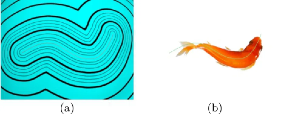
Fig.3 Geodesic polar coordinates.(a)Our LC-enhanced SVG method is able to compute the geodesic distances for curved sources. Each offset curve is parameterized by arc-length.(b)The offset distance δ together with the normalized arc-length︿s form the geodesic polar coordinate system.This uniquely determines a point on the 3D surface,and defines a bijective map between R2and the patch on 3D surface.
Both Sun et al.’s method and Schmidt’s method require local remeshing,which is a significant overhead,especially if the patch to be parameterized is large.Instead, we propose a simple-yeteffective method for computing polar coordinates. Our method is completely integrated into the geodesic computation framework,and the induced parameterization is guaranteed to induce a bijective map.
Note that the combined SVG and GTU method can compute geodesic distances from both point sources and curve sources. Here we discuss the case of curve sources,since point sources are a special case.Consider a source curve Cs.The uaxis lies along Csand u ranges from 0 to 1 after normalization by the arc-length of Cs.Each geodesic offset curve is then parameterized by arc-length to get the corresponding u values.Consider Fig.4. Let Ciand Cjbe two iso-curves with a,c being two corresponding starting points.Let b,d be two arbitrary points on curves Ciand Cj,respectively. The ubvalue at point b is,where l(a,b) represents the length of curve between a and b. Similarly,the udvalue at point d isThe u value of each point is only related to the arc-length on the corresponding iso-curve,meaning that the polar coordinate is guaranteed to be bijective.In contrast to Ref.[48],our method does not solve any linear system,so is numerically stable and efficient. A computational comparison shows that our method is up to 10 times faster than the one in Ref.[48](see Fig.5).
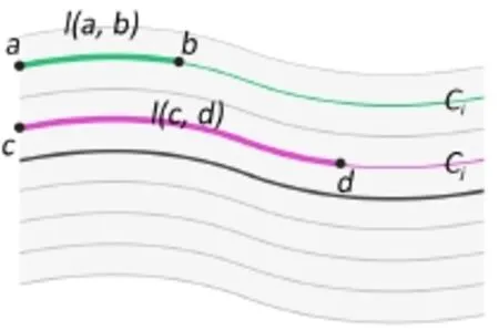
Fig.4 Polar coordinates on iso-curves.
4 Parallel distribution of anisotropic shapes
Two simple circular shapes do not overlap if the sum of the radii of their circumcircles is greater than the distance between their centers.In Ref.[8],ellipsoidal shapes are represented using an anisotropic metric and conflict checking can be done in the same way as for circles.Our algorithm handles more flexible and complicated shapes,such as birds,fishes,and branches,not just circles or ellipses.Moreover,our algorithm is designed for parallel computation to ensure efficiency of the distribution process. Our algorithm has two stages: (i)the user specifies the input shape(s),the global vector field,and the density control on the 3D mesh surfaces;(ii) following the user’s specification,the input shapes are randomly distributed and rendered in parallel. We explain details of these steps in the rest of this section.

Fig.5 Comparison of(a)extended exponential map and(b)geodesic polar coordinates.The latter produces results with comparable quality to the former.However,the former computes a harmonic map to fix the non-bijectivity of the exponential map,so it is more computationally expensive than our method.Their method takes 1.7 s to parameterize this 10K-vertex patch,whereas our method takes only 0.18 s,while distortions due to geodesic approximation are acceptable.
4.1 User input
In our system,user inputs are of three types: shape(s),a global vector field,and a density control.
Shape(s):The user can supply arbitrary images as input shapes.If only one simple circular shape is supplied,our algorithm works in the same way as traditional blue noise sampling.Multiple shapes are also supported in our system.By increasing the number and changing the types of the shapes,the user is able to create more artistic and vivid results.
Global vector field:The global vector field is used to guide the shapes’directions and is created everywhere on the input mesh surface.The direction of a shape is determined by a curve aligned with the global vector field.Note that the direction here is not a simple three-element vector in 3D space:the track(curve-segment)on the mesh surfaces can have shapes pasted along it.
We adopt the optimal method provided by Crane et al.[50]to generate the global vector field. It is controlled directly by setting singularities and direction constraints on the surface,as shown in Fig.6(a).Each singularity has an index indicating the number of full rotations along a small loop around it.These indices must be chosen in such a way as to guarantee their sum equals the Euler characteristic of the input mesh.The user can also sketch strokes on the mesh surface to specify the general vector field direction.After doing so,the global vector field is computed by solving a convex optimization problem with linear constraints.
Density control: The user may specify the density globally and locally.Unlike in traditional sampling algorithms,we use the distribution of curve-segments following the global vector field to represent the density control. The user initially inputs a sampling rate to globally define the density. Then a set of curve-segments is generated in parallel following the global vector field during the sampling process: each time we throw a sampling point, we start tracing a new curve-segment from it along the direction interpolated from the global vector field. The density changes locally if the number of the curve-segments inside the selected area changes,which can also be thought as the length of the corresponding curve-segments being increased/decreased.The user can interactively scale the length of the curve-segments in a selected area with different density factors by using a customized brush.Note that the number of generated curvesegments could be more than required for the actual shapes distributed on the mesh surface:as well as density control,the distribution of shapes is also affected by our conflict checking scheme.
4.2 Single-class shape distribution
When 2D shapes are mapped to the input mesh surfaces along curve-segments,to make sure they do not intersect each other,we need an efficient method of conflict checking.If a shape is long,we split it into equal size parts and check each part using a pre-computed distance table,as Fig.7 briefly illustrates.
We now explain the details of the distance table technique.Given a 2D object S,we compute the smallest covering circumcircle⊙(c,r),where c is the center and r is the radius of S(see Fig.8).The circle can be computed in linear time using the approach in Ref.[51].We then choose a ray L from the center c in a fixed direction as the polar axis.Clearly,objects are guaranteed to be free of conflicts if the distance
between their centers is greater than 2r.Objects within 2r may or may not conflict,depending on their orientations.

Fig.6 Algorithm pipeline for single-class shape distribution.(a)User specifies a scalar field to control the shape density,including locations of singularities and their indices.(b)We adopt Crane et al.’s method[50]to compute a global vector field which controls the shape orientation. (c)Our method automatically determines the locations,sizes,and orientations of the 2D objects.Each blue curve-segment represents the center-line of one object.(d)All distributed objects are guaranteed to be collision-free.
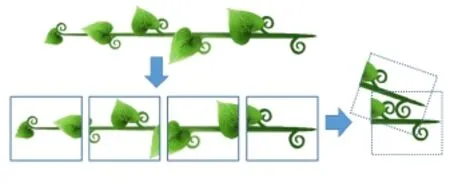
Fig.7 Long shapes are divided into several parts whose intersection is tested separately.
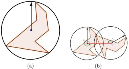
Fig.8 (a)The circumcircle of shape and(b)the minimum safe distance between two shapes(red line).
To efficiently determine whether or not two objects conflict,we pre-compute a lookup table,the minimum safe distance table(MSDT).
As shown in Fig.8,the relation between two objects siand sjis determined by the distance between two center points d(ci,cj)and the orientation of each object.The latter is characterized by the angles between the local polar axes at cj,cjand the line cicj,denoted by αiand αj,respectively.
We uniformly divide[0,2π)into kaangle intervals, and build a ka×kalookup table.For each pair of angles{αi,αj},the entry d(αi,αj)≤ 2r is the minimum distance between the center points to guarantee no conflict.It is computed as follows.
If the object is a 2D polygon with e edges,we can check for polygon intersection in O(e2)time.In the interval[0,2r]if we pick krchecking points,then the binary search for intersection of two polygons at these points has O(e2log kr)time complexity.Precomputing the MSDT can be done intime andspace.
If the object is a 2D image with b boundary pixels, the intersection of two objects siand sjis detected by checking each of their boundary pixels.siand sjare in conflict if any boundary pixel of siis inside sj. Assuming that these pixels are sorted by their indices,we can test whether two objects are conflicted in O(b)time complexity. Overall, construction of the MSDT takestime andspace.
More space and time are required for precomputing MSDT if we increase the value of kaor krto distribute more shapes(see Fig.9).
By default,the density factor is set to 1 for the whole input mesh. If the density factor is changed,then an adaptive shape distribution is defined.Let fi,fjbe the density factors of the local regions around points ciand cj,respectively.A new minimum safe distancebetween siand sjcan be approximated from the old distanceas below:

Assume that curves have been generated on the input mesh and we want to distribute shapes following these curves.Since the SVG graph is precomputed for the input mesh,the distance between center points ci,cjand the angles{αi,αj}can be computed efficiently.Thus in our algorithm,the
conflict detection for a curve cican be done without computing the geodesic polar coordinates of whole local disk⊙(ci,2r)around the curve-source.

Fig.9 Comparison with Poisson disk sampling.Top:Poisson disk sampling considers each sample as a disk and does not allow overlapping disks(a),allowing 103 stars to be distributed in(b). Bottom:Our method allows a more dense distribution than Poisson disk sampling,while preventing stars from overlapping.It randomly distributes 221 stars in(c)and greedily distributes 333 stars in(d).

Input:Input shape S with radius r. Output:Minimum safe distance table D. function ParallelMSDTGeneration() b←find boundary pixels of S c←random 2D point parallel for i from 0 to ka−1 do b'←rotate b with angle 2πi/kaaround c d←0 for j from 1 to krdo d←2jr/krb1←affine translate b'from c with distance d if b∩b1==Ø then break end if end for for j from 0 to ka−1 do α←2πj/kabeta←α+2πi/kaD(α,β)←d D(β,α)←d end for parallel end for return D
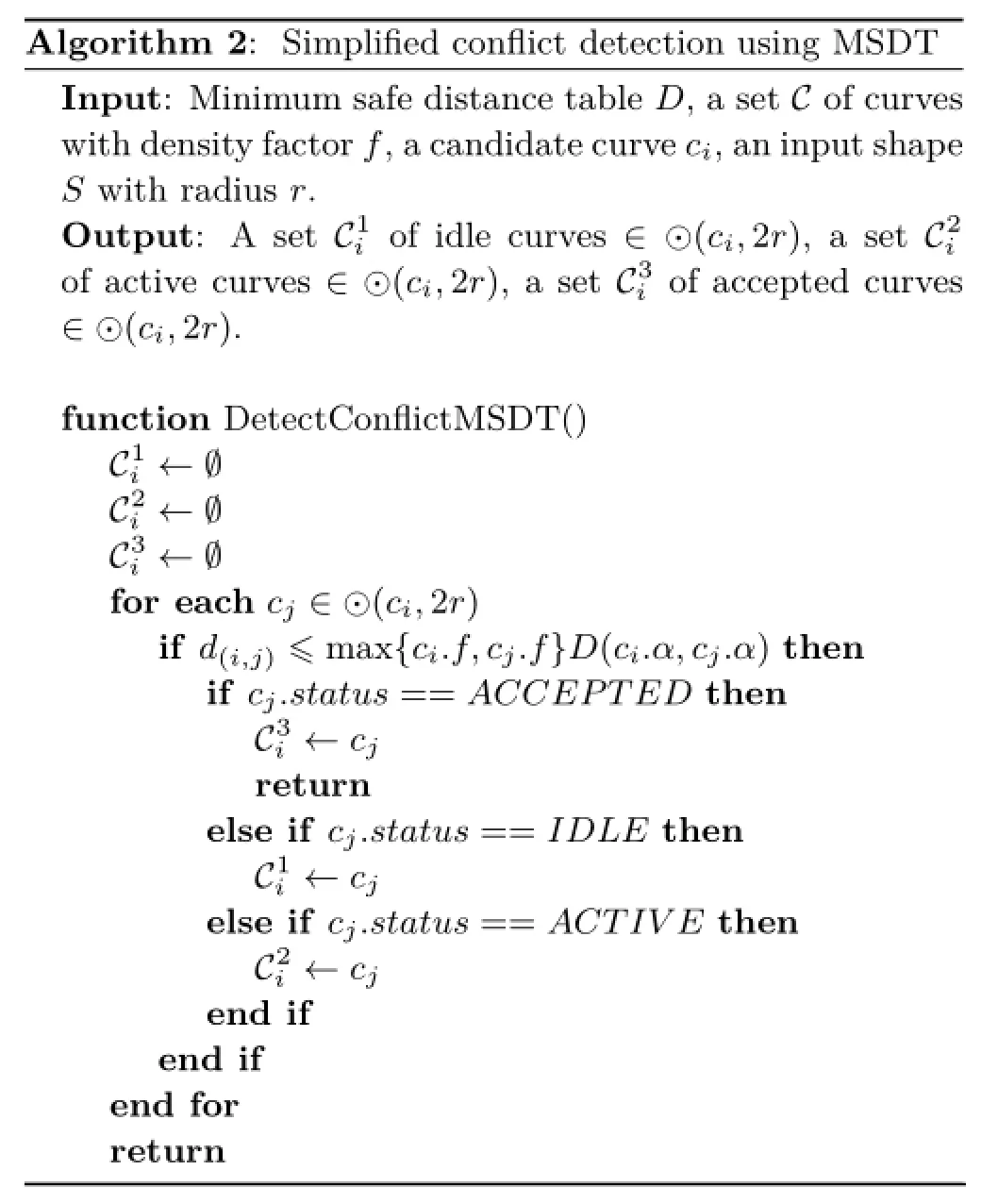
Algorithm 2:Simplified conflict detection using MSDT Input:Minimum safe distance table D,a set C of curves with density factor f,a candidate curve ci,an input shape S with radius r. Output:A set C1iof idle curves∈⊙(ci,2r),a set C2iof active curves∈⊙(ci,2r),a set C3iof accepted curves∈⊙(ci,2r). function DetectConflictMSDT() C1i←Ø C2i←Ø C3i←Ø for each cj∈⊙(ci,2r) if d(i,j)≤max{ci.f,cj.f}D(ci.α,cj.α)then if cj.status==AC C E P T E D then C3i←cjreturn else if cj.status==I D LE then C1i←cjelse if cj.status==AC T I V E then C2i←c j end if end if end for return

Algorithm 3:Simplified parallel single shape distribution with T threads Input:Triangle mesh M,minimum safe distance table D,a set C of curves with density factor f,input shape S. Output:A set P of parameterized regions. function ParallelSingleClassShapeDistribution() P←Ø C.status←I DLE while C/=Ø do for each thread i from 1 to T ci←C.f ront() C.pop f ront() ci.status←AC T IV E ci.priority← rand()∗T+iRAN D M AX T end for r←compute radius of S parallel for each thread i from 1 to T C1i ←Ø//idle curves∈⊙(ci,2r) C2i ←Ø//active curves∈⊙(ci,2r)i,C2i,C3i} end if parallel end for end while return P function CheckStatus(ci,C3i) if atomic ci.status/=AC T I V E then return end if for each cj∈C3iif cj.prior ity>ci.prior ity then CheckStatus(cj,C3j) if cj.status==AC C E P T E D then atomic ci.status←RE J E C T E D return end if end if end for atomic ci.status←AC C E P T E D return←Ø//accepted curves∈⊙(ci,2r) {C1i,C2i,C3i}←DetectConflictMSDT(ci,r,D) if C3i/=Ø then ci.status←R E J E C T E D C1i←Ø C2i←Ø end if parallel end for parallel for each thread i from 1 to T CheckStatus(ci,C3i) if ci.status==AC C E P T E D then P←find parameterized region centered at ciatomic C{C1C3i
The pseudo-code in Algorithm 3 describes a simplified version of our method for single-class distribution.
4.3 Multi-class shape distribution
Our system can distribute input shapes of multiple classes without overlapping.For a group of m input shapes S={S1,S2,...,Sm},we have to computeMSDTs between all different classes and m MSDTs for each single class.Thus for a shape with b boundary pixels,the time complexity of our method isand it takesmemory space.
In the multi-class case,a point or curve could be rejected because of conflict with one class,but re-accepted later by others. If an object siof class Si∈S is a candidate for conflict checking with its neighboring objects{sj}in corresponding classes Sj∈S,we can use a general minimum safe distance,S j∈S,j= 1,...,kafor fast distribution,or use all minimum safe distanceskafor a denser distribution. We can also approximate d(αi,αj)fromusing a different priority for each class to get non-uniform shape distributions of all classes.
The impact of the density factor in the multi-class case is the same as for single-class case.
5 Experimental results
5.1 Performance
We implemented our algorithm in C++and tested it on a 2.66 GHz Intel Xeon quad-core CPU.We used OpenMP to parallelize our algorithm to take advantage of all CPU cores.We observed that our parallel implementation on a quad-core CPU was up to 3 times faster than when using a single-core;it allows interactive manipulation on 3D models with 100K faces.See Table 3 for performance and the accompanying video demonstration in the Electronic Supplementary Material(ESM).

Table 3 Mesh complexity and performance of shape distribution processes.T1and T4:running time on a quad-core CPU using a single core and all cores,respectively
Figures 10,11,and 12 demonstrate results for single-class and multi-class shape distributions.
5.2 Robustness
Our method is intrinsic since both the collision detection and shape distribution depend on the metric only.Thanks to the intrinsic nature of the geodesic algorithms[41,42],our method is insensitive to mesh resolution and tessellation.See Fig.13 for our results on the Bimba model with various resolutions.
5.3 Comparison to Ref.[8]

Fig.10 Single-class shape distribution on the Kitten model with different density values and textures.We control the density f by using a brush with the center at the left eye and user-defined radius r.The default value of f is 1.0.For the region inside the brush we have f=min{0.25,d/r}where d is the geodesic distance to the center.
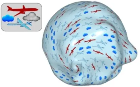
Fig.11 Multi-class shape distribution on a bumpy sphere with 50K faces.

Fig.12 Further results of multi-class shape distribution on(a)Gargoyle and(b)Sculpture models.
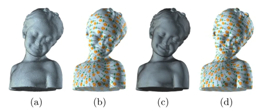
Fig.13 Our method works well on the Bimba model with various resolutions:30K faces in(a)and(b),150K faces in(c)and(d).
Our method is based on dart throwing,so it fulfills the blue noise sampling property.Our method and the anisotropic blue noise sampling method [8]differ as follows.Firstly,the latter method is mainly designed for 2D problems. Although it can be extended to 3D surfaces via global parameterization,computing a highquality parameterization for high-genus models is technically challenging.Our method is based on local parameterizations,which can be computed efficiently on the fly.Therefore,our method can be applied to models of arbitrary geometry and topology. Secondly,their parallelization techniques are hard to extend to meet anisotropy requirements,since anisotropy poses a challenge in domain partitioning. Thirdly,their method abstracts anisotropic shapes as bounding ellipses to allow collision detection and quality evaluation to be done in an analytical manner. However,an ellipse is not an effective representation if the 2D shape has a highly concave boundary.As a result,their method may produce a distribution which is far from optimal.Thanks to the minimum safe distance table,our method can faithfully represent the geometry of the 2D shapes thereby allowing a much denser distribution.Last but not least,their method supports single-class sampling only,whereas our method can compute multi-class shape distributions(see Fig.14).
5.4 Comparison to Ref.[24]

Fig.14 Comparison to Ref.[8].The 2D eagle shape is highly concave,so a simple bounding ellipse cannot capture its geometric features. As a result,requiring non-overlapping ellipses is very pessimistic.Li et al.’s method[8]can distribute only 115 eagles(left) which is clearly suboptimal.Our method produces a much more dense distribution,containing 224 eagles(right),as it allows overlapping ellipses in which adjacent eagles still do not collide.
Both our method and Hu et al.’s optimization-
based method densely distribute irregular tiles of multiple classes with variable size without overlapping(see Fig.9). However,our method has some advantages: it supports long irregular tiles,which are unsuitable for Voronoi diagram approximation.The optimization process in Ref.[24] requires local parameterizations to be computed multiple times,meaning it is surely outperformed by our pre-computed approach.In our method,the user can flexibly control density and direction of tiles, without re-computing local parameterizations.
6 Conclusions
This paper presents a practical method for computing anisotropic 2D shape distributions on arbitrary meshes with user control. Unlike existing sampling approaches, which usually assume the 2D shapes are isotropic with simple geometrical topology,our method can handle complex 2D shapes and guarantee they are placed without overlap. In our method,distribution of multiple classes is also supported following a global vector field. Some parameters are provided,so the user can flexibly control the directions and density of the distribution.Instead of using global parameterization of the input mesh,our method computes local geodesic polar coordinates with little computational cost.Therefore,it can be applied to models of complicated geometry and topology.Last but not least,our method has a natural parallel structure and can be implemented on multi-core CPUs to achieve high performance.Experimental results on a wide range of 3D models and 2D anisotropic shapes are provided to demonstrate the effectiveness of our method.
Electronic Supplementary Material Supplementary material is available in the online version of this article at http://dx.doi.org/10.1007/s41095-016-0057-1.
[1]Wei,L.Y.Parallel Poisson disk sampling.ACM Transactions on Graphics Vol.27,No.3,Article No. 20,2008.
[2]Ebeida,M.S.;Davidson,A.A.;Patney,A.;Knupp, P.M.;Mitchell,S.A.;Owens,J.D.Efficient maximal Poisson disk sampling.ACM Transactions on Graphics Vol.30,No.4,Article No.49,2011.
[3]Yan,D.M.;Wonka,P.Gap processing for adaptive maximal Poisson disk sampling.ACM Transactions on Graphics Vol.32,No.5,Article No.148,2013.
[4]Wei,L.Y.Multi class blue noise sampling.ACM Transactions on Graphics Vol.29,No.4,Article No. 79,2010.
[5]Chen,J.;Ge,X.;Wei,L.Y.;Wang,B.;Wang,Y.;Wang,H.;Fei,Y.;Qian,K.L.;Yong,J.H.;Wang, W.Bilateral blue noise sampling.ACM Transactions on Graphics Vol.32,No.6,Article No.216,2013.
[6]Bowers,J.;Wang,R.;Wei,L.Y.;Maletz,D.Parallel Poisson disk sampling with spectrum analysis on surfaces.ACM Transactions on Graphics Vol.29,No. 6,Article No.166,2010.
[7]Ying, X.; Xin, S.Q.; Sun, Q.; He, Y. An intrinsic algorithm for parallel Poisson disk sampling on arbitrary surfaces.IEEE Transactions on Visualization and Computer Graphics Vol.19,No.9, 1425–1437,2013.
[8]Li,H.;Wei,L.Y.;Sander,P.V.;Fu,C.W.Anisotropic blue noise sampling.ACM Transactions on Graphics Vol.29,No.6,Article No.167,2010.
[9]Peyrot,J.L.;Payan,F.;Antonini,M.Feature preserving direct blue noise sampling for surface meshes.In:Eurographics 2013–Short Papers.Otaduy, M.A.;Sorkine,O.Eds.The Eurographics Association, 9–12,2013.
[10]Quinn,J.A.;Langbein,F.C.;Lai,Y.K.;Martin,R. R.Generalized anisotropic stratified surface sampling. IEEE Transactions on Visualization and Computer Graphics Vol.19,No.7,1143–1157,2013.
[11]Zhong,Z.;Guo,X.;Wang,W.;Lévy,B.;Sun,F.;Liu,Y.;Mao,W.Particle based anisotropic surface meshing.ACM Transactions on Graphics Vol.32,No. 4,Article No.99,2013.
[12]Chen,Z.;Yuan,Z.;Choi,Y.K.;Liu,L.;Wang,W. Variational blue noise sampling.IEEE Transactions on Visualization and Computer Graphics Vol.18,No.10, 1784–1796,2012.
[13]Liang,G.;Lu,L.;Chen,Z.;Yang,C.Poisson disk sampling through disk packing.Computational Visual Media Vol.1,No.1,17–26,2015.
[14]Dunbar,D.;Humphreys,G.A spatial data structure for fast Poisson disk sample generation.ACM Transactions on Graphics Vol.25,No.3,503–508, 2006.
[15]Gamito, M.N.; Maddock, S.C.Accurate multidimensional Poisson disk sampling. ACM Transactions on Graphics Vol.29,No.1,Article No. 8,2009.
[16]Fattal,R.Blue noise point sampling using kernel density model.ACM Transactions on Graphics Vol. 30,No.4,Article No.48,2011.
[17]Cohen,M.F.;Shade,J.;Hiller,S.;Deussen,O. Wang Tiles for image and texture generation.ACM Transactions on Graphics Vol.22,No.3,287–294, 2003.
[18]Kopf,J.;Cohen Or,D.;Deussen,O.;Lischinski,D. Recursive Wang tiles for real time blue noise.ACM Transactions on Graphics Vol.25,No.3,509–518, 2006.
[19]Ostromoukhov,V.Sampling with polyominoes.ACM Transactions on Graphics Vol.26,No.3,Article No. 78,2007.
[20]Zhou,Y.;Huang,H.;Wei,L.Y.;Wang,R. Point sampling with general noise spectrum.ACM Transactions on Graphics Vol.31,No.4,Article No. 76,2012.
[21]Lai,Y.K.;Hu,S.M.;Martin,R.R.Surface mosaics. The Visual Computer Vol.22,No.9,604–611,2006.
[22]Dos Passos,V.A.;Walter,M.3D mosaics with variablesized tiles.The Visual Computer Vol.24,No. 7,617–623,2008.
[23]Dos Passos,V.A.;Walter,M.3D virtual mosaics: Opus palladium and mixed styles.The Visual Computer Vol.25,No.10,939–946,2009.
[24]Hu,W.;Chen,Z.;Pan,H.;Yu,Y.;Grinspun,E.;Wang,W.Surface mosaic synthesis with irregular tiles. IEEE Transactions on Visualization and Computer Graphics Vol.22,No.3,1302–1313,2016.
[25]Sun,X.;Zhou,K.;Guo,J.;Xie,G.;Pan,J.;Wang, W.;Guo,B.Line segment sampling with blue noise properties.ACM Transactions on Graphics Vol.32, No.4,Article No.127,2013.
[26]Battiato,S.;Milone,A.;Puglisi,G.Artificial mosaic generation with gradient vector flow and tile cutting. Journal of Electrical and Computer Engineering Vol. 2013,Article No.8,2013.
[27]Hausner,A.Simulating decorative mosaics.In: Proceedings of the 28th Annual Conference on Computer Graphics and Interactive Techniques,573–580,2001.
[28]Feng,L.;Hotz,I.;Hamann,B.;Joy,K.Anisotropic noise samples.IEEE Transactions on Visualization and Computer Graphics Vol.14,No.2,342–354,2008.
[29]Li,H.;Lo,K.Y.;Leung,M.K.;Fu,C.W. Dual Poisson disk tiling: An efficient method for distributing features on arbitrary surfaces.IEEE Transactions on Visualization and Computer Graphics Vol.14,No.5,982–998,2008.
[30]Mitchell,J.S.B.;Mount,D.M.;Papadimitriou,C. H.The discrete geodesic problem.SIAM Journal on Computing Vol.16,No.4,647–668,1987.
[31]Chen,J.;Han,Y.Shortest paths on a polyhedron. In:Proceedings of the 6th Annual Symposium on Computational Geometry,360–369,1990.
[32]Liu,Y.J.Exact geodesic metric in 2 manifold triangle meshes using edge based data structures.Computer Aided Design Vol.45,No.3,695–704,2013.
[33]Surazhsky,V.;Surazhsky,T.;Kirsanov,D.;Gortler, S.J.;Hoppe,H.Fast exact and approximate geodesics on meshes.ACM Transactions on Graphics Vol.24, No.3,553–560,2005.
[34]Xin,S.Q.;Wang,G.J.Improving Chen and Han’s algorithm on the discrete geodesic problem.ACM Transactions on Graphics Vol.28,No.4,Article No. 104,2009.
[35]Xu,C.;Wang,T.Y.;Liu,Y.J.;Liu,L.;He,Y.Fast wavefront propagation(FWP)for computing exact geodesic distances on meshes.IEEE Transactions on Visualization and Computer Graphics Vol.21,No.7, 822–834,2015.
[36]Ying,X.;Xin,S.Q.;He,Y.Parallel Chen–Han(PCH) algorithm for discrete geodesics.ACM Transactions on Graphics Vol.33,No.1,Article No.9,2014.
[37]Qin,Y.;Han,X.;Yu,H.;Yu,Y.;Zhang,J.Fast and exact discrete geodesic computation based on triangle oriented wavefront propagation.ACM Transactions on Graphics Vol.35,No.4,Article No.125,2016.
[38]Sethian,J.A.A fast marching level set method for monotonically advancing fronts.Proceedings of the National Academy of Sciences of the United States of America Vol.93,No.4,1591–1595,1996.
[39]Crane,K.;Weischedel,C.;Wardetzky,M.Geodesics in heat:A new approach to computing distance based on heat flow.ACM Transactions on Graphics Vol.32, No.5,Article No.152,2013.
[40]Campen,M.;Heistermann,M.;Kobbelt,L.Practical anisotropic geodesy.Computer Graphics Forum Vol. 32,No.5,63–71,2013.
[41]Xin,S.Q.;Ying,X.;He,Y.Constant time all pairs geodesic distance query on triangle meshes.In: Proceedings of the ACM SIGGRAPH Symposium on Interactive 3D Graphics and Games,31–38,2012.
[42]Ying,X.;Wang,X.;He,Y.Saddle vertex graph (SVG):A novel solution to the discrete geodesic problem.ACM Transactions on Graphics Vol.32,No. 6,Article No.170,2013.
[43]Dijkstra,E.W.A note on two problems in connexion with graphs.Numerische Mathematik Vol.1,No.1, 269–271,1959.
[44]Bertsekas,D.P.A simple and fast label correcting algorithm for shortest paths.Networks Vol.23,No.8, 703–709,1993.
[45]Bertsekas,D.P.;Guerriero,F.;Musmanno,R. Parallel asynchronous label correcting methods for shortest paths.Journal of Optimization Theory and Applications Vol.88,No.2,297–320,1996.
[46]Schmidt,R.;Grimm,C.;Wyvill,B.Interactive decal compositing with discrete exponential maps.ACM Transactions on Graphics Vol.25,No.3,605–613, 2006.
[47]Wang,X.;Ying,X.;Liu,Y.J.;Xin,S.Q.;Wang, W.;Gu,X.;Mueller Wittig,W.;He,Y.Intrinsic computation of centroidal voronoi tessellation(CVT) on meshes.Computer Aided Design Vol.58,51–61, 2015.
[48]Sun,Q.;Zhang,L.;Zhang,M.;Ying,X.;Xin,S.Q.;Xia,J.;He,Y.Texture brush:An interactive surface texturing interface.In: Proceedings of the ACM SIGGRAPH Symposium on Interactive 3D Graphics and Games,153–160,2013.
[49]Schmidt, R.Stroke parameterization.Computer Graphics Forum Vol.32,No.2pt2,255–263,2013.
[50]Crane,K.; Desbrun,M.; Schröder,P.Trivial connections on discrete surfaces.Computer Graphics Forum Vol.29,No.5,1525–1533,2010.
[51]Megiddo,N.Linear time algorithms for linear programming in R3 and related problems.In: Proceedings of the 23rd Annual Symposium on Foundations of Computer Science,329–338,1982.

Qian Sun received her Ph.D.degree in computer science from Nanyang Technological University, Singapore. She is currently a research fellow in Fraunhofer IDM@NTU.Her current research interests include human–computer interaction, computer graphics,and data visualization.
Xiaoning Wang received his B.Eng. degree from Tianjin University,China, in 2011,and Ph.D.degree from Nanyang Technological University, Singapore. He is currently a research fellow in the School of Computer Science and Engineering, Nanyang Technological University. His research interests are geometric analysis and computer graphics.

Tien Hung Le received his B.Eng. degree in computer engineering from Bauman Moscow State Technical University, Russia,in 2009.He is currently a Ph.D.candidate in the School of Computer Science and Engineering, Nanyang Technological University,Singapore. His research interests include computing geodesics,point set surfaces, and surface parameterization.
Xiang Ying received his Ph.D.degree in computer science from Nanyang Technological University,Singapore.He is currently an associate professor in Tianjin University,China.His research interests include computer graphics, virtual reality,and GPU computing.
Ying He is currently an associate professor in the School of Computer Science and Engineering, Nanyang Technological University,Singapore.He received his B.S.and M.S.degrees in electrical engineering from Tsinghua University,China,and Ph.D.degree in computer science from Stony Brook University,USA.His research interests fall into the general area of visual computing and he is particularly interested in the problems which require geometric analysis and computation. For more information,please visit http://www.ntu.edu.sg/home/yhe.
Open Access The articles published in this journal are distributed under the terms of the Creative Commons Attribution 4.0 International License(http:// creativecommons.org/licenses/by/4.0/), which permits unrestricted use,distribution,and reproduction in any medium,provided you give appropriate credit to the original author(s)and the source,provide a link to the Creative Commons license,and indicate if changes were made.
Other papers from this open access journal are available free of charge from http://www.springer.com/journal/41095. To submit a manuscript,please go to https://www. editorialmanager.com/cvmj.
© The Author(s)2016.This article is published with open access at Springerlink.com
 Computational Visual Media2016年4期
- Computational Visual Media的其它文章
- LSTM-in-LSTM for generating long descriptions of images
- Texture image classification with discriminative neural networks
- Weighted average integration of sparse representation and collaborative representation for robust face recognition
- Modified filtered importance sampling for virtual spherical Gaussian lights
- A computational model of topological and geometric recovery for visual curve completion
- Computational design of iris folding patterns
