Dynamic stability of quadruped robot walking on slope with trot gait①
Lei Jingtao(雷静桃), Ren Mingming
(School of Mechatronic Engineering and Automation, Shanghai University, Shanghai 200072, P.R.China)
Dynamic stability of quadruped robot walking on slope with trot gait①
Lei Jingtao(雷静桃)②, Ren Mingming
(School of Mechatronic Engineering and Automation, Shanghai University, Shanghai 200072, P.R.China)
The dynamic stability of a quadruped robot trotting on slope was analyzed. Compared with crawl gait, trot gait can improve walking speed of quadruped robots. When a quadruped robot trots, each leg is in the alternate state of swing phase or supporting phase, and two legs in the diagonal line are in the same phase. The feet in the supporting phase form a supporting region on the ground. When a quadruped robot walks on slope, the vertical distance from zero moment point (ZMP) to the supporting diagonal line is defined as ZMP offset distance. Whether this distance is less than the maximum offset distance or not, the stability of robot trotting on slope can be judged. The foot trajectory was planned with the sinusoidal function.Based on the kinematic analysis, the ZMP offset distance of quadruped robot under different slope angles, step length and step height was calculated, then the reasonable slope angle, step length and step height for quadruped robot trotting on slope to keep dynamic stability can be determined. On the other hand, the posture angle of quadruped robot should be controlled within the desired range. Computer simulations were executed to verify the theoretical analysis.The study will provide reference for determining reasonable step parameters of the quadruped robot.
quadruped robot, slope, trot gait, stability, zero moment point (ZMP)
0 Introduction
Mobile robots are generally divided into legged, wheeled, tracked and mixed. The quadruped robots have been popularly studied by many research groups[1]because of its advantages over wheeled or tracked locomotion, such as obstacle striding, high terrain adaptability, environmental protection and energy saving. Of course the legged robot has some disadvantages such as more complex structure, which keeps it from being used.
When walking in an unstructured environment, compared to wheeled or tracked robots, legged robot has some advantages. Four-legged robot has the performance of more stable than biped robot, simple structure than the six-legged robot.
The locomotion style of animals changes with different environments, which differ from the uneven terrain such as gravel road and mountainous terrain, specialterrain such as stairs and sand beaches, extreme terrain such as snow or swamp.
It is difficult for a quadruped robot to walk as an animal does. Quadruped robots can not achieve the mobility and dynamic stability similar to four-legged creatures, since a quadruped robot is a multi DOF system. During walking, the robot has the characteristics of changing configuration. On the other hand, the terrain of the unstructured environment is complex, such as, slope, obstacle and so on. The ground reaction forces, sliding and friction and other factors influence stability. It is difficult to achieve dynamic stability for quadruped robots walking in the unstructured environment.
The stability of a walking robot is divided into static and dynamic according to different gait style. The trot gait belongs to the dynamic one. When a quadruped robot walks with crawl gait, it is easy to keep stable, but the walking speed is lower. As developed recently, a robot with trot gait, can improve effectively the walking speed. It is necessary to analyze its dynamic stability in unstructured environment.
Some researchers have analyzed the dynamic stability of the quadruped robot with trot gait. The ZMP stability criterion is generally used to analyze the stability of walking robot[2,3]. Ref.[4] proposed a control method for quadruped robot with trot gait pass through the plain and slope transition. Ref.[5] presented that a quadruped robot could perform self-stable running behavior by designing mechanical structure to expand the self-stable region. Ref.[6] presented the centroid trajectory of quadruped robot walking with crawl gait, and discussed on a strategy to maintain the best walking balance. Ref.[7] proposed a kind of walking pattern generator with the selection of every foot placement such as the COG of the robot follows a stable trajectory characterized by a stability margin relative to the current support triangle. Ref.[8] presented a kind of trajectory planning for quadruped robot, which causes the robot to have versatile motion in different directions. The ZMP criterion method is used to analyze dynamic stability. The minimum and maximum of lateral movement of the body is specified to maintain location of the ZMP in the supporting region. Ref.[9] analyzed the stability of the quadruped robot by simulation, and presented that the robot should have proper leg configuration to increase stability by decreasing pitching motion of the robot. Ref.[10] discussed omin-directional walking of the quadruped robot walking on slope. A kind of successive gait-transition method is presented, and the stability is discussed by a measure of stability margin. Ref.[11] presented a center of pressure method to evaluate the stability of the quadruped robot with crawl gait.Turning gait is the most general and important factor for omni-directional walking of walking robot. Ref.[12] presented the turning gait planning for six-legged robot, and stability is analyzed based on the normalized energy stability margin method. Ref.[13] proposed the omni-directional static walking method on a slope, and the stability in gait transition processes was analyzed. The stability analysis of quadruped robot with trot gait is mostly focused on motion over a flat terrainor walking along straight line.Study on the dynamic stability of the quadruped robot walking in the unstructured environment is limited.
In this study, the dynamic stability of the quadruped robot trotting on slope was analyzed. Firstly, the foot trajectory of the quadruped robot is planned with sinusoidal function. When the quadruped robot walks with trot gait, the vertical distance from ZMP to the supporting diagonal line is defined as the ZMP offset distance, which is used as the dynamic stability criterion.When the quadruped robot walks in different slope conditions, the ZMP offset distance is calculated, respectively. On the one hand, the reasonable gait parameters and slope angle for quadruped robot dynamic stable walking on slope with trot gait can be determined according to the ZMP offset distance. On the other hand, the posture angle of quadruped robot should be controlled to ensure the dynamic walking stability.
1 Trot gait
Quadruped robot is composed of one body and four legs, as shown in Fig.1. Each leg is designed with three rotational joints, which are side-swing-hip joint, forward-swing- hip joint and knee joint.

Fig.1 Quadruped robot
The gait style of the quadruped robot are crawl, trot, pace and jump. Trot gait is faster but is more unstable than crawl gait. When the quadruped robot walks with trot gait, four legs are classified into two groups, two legs on the diagonal line belong to one group. Two legs that belong to the same group are lifting, swing, falling, supporting synchronously. The leg mechanism is alternately in swing phase and supporting phase.Two legs transfer forward, while the other legs support the body weight and push itself against the ground to generate the needed thrust in the desired direction of motion.
Two parameters can describe the trot gait, which are duty factor βiand leg phase φi(i=1,2,3,4). The gait formula g=[β1, β2, β3, β4; φ1, φ2, φ3, φ4] is generally used to describe lift and fall sequence of each leg and the interval time between adjacent legs.
If the periodic gait is adopted and the duty factor is 0.5, the time in supporting phase and swing phase of each leg is equal, as shown in Fig.2.
Then the gait formula is
(1)
The ZMP criterion method is used to analyze dynamic stability of bipedal or quadruped robot.
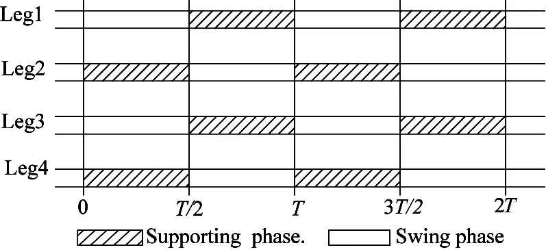
Fig.2 Different phase
Definition:
(1) The supporting polygon: the region formed by the feet in supporting phase, as shown in Fig.3.
(2) ZMP offset distance d: the vertical distance from ZMP to the supporting diagonal line.
(3) Maximum offset distance Δ: the vertical distance from the supporting diagonal line to the polygon boundary.
The supporting region is shown in Fig.3, which is determined by the foot sizee. During the former half gait cycle, the 2th leg and 4th leg are in supporting phase. During the latter half gait cycle, the 1th leg and 3th leg are in supporting phase, the stable offset distance d is from ZMP to supporting diagonal line.

Fig.3 The supporting polygon and offset distance
The stability judgment condition is: If d<Δ, ZMP locate inside the supporting polygon, robot can keep stable. If d>Δ, ZMP locate outside the supporting polygon, robot is unstable. So the dynamic stability of the quadruped robot walks on slope with trot gait should meet the condition: ZMP offset distance d less than maximum offset distance Δ.
On the one hand, the robot walk on slop, the ZMP should be controlled within the supporting region, which is related to the gait parameters. On the other hand, the posture angle of robot should be controlled.
2 Kinematics
2.1 Trajectory planning
The trajectory function should be continuous and smooth. The combined cycloid function can effectively reduce the contact force between feet and environment[14]. The cycloid function, sinusoidal function or linear function is generally adopted as the foot trajectory, and different trajectories will provide different dynamic performance for quadruped robot.
The trajectory planning was done in Cartesian coordinates. As the side swing movement of the leg mechanism needn’t be considered,so the trajectory function was divided into two directions. The functions along thex-axis andz-axis direction were planned by the sinusoidal function. According to the boundary constraint conditions:
px|t=0= 0, px|t=Tsw=S, pz|t=0=0,
pz|t=Tsw=H
The trajectory function can be determined as
(2)
Where S is step length,H is step height, px, py, pzis the foot displacement along coordinate axis direction, respectively.
The Denavit-Hartenberg coordinate method was adopted to analyze the kinematics of quadruped robot trotting on the slope, the spatial position and pose relationship between the foot and leg joints can be derived. Because of each leg is alternately in swing phase and supporting phase, so the kinematic of leg in different phase is different.
2.2 Forward kinematics of leg in swing phase
Quadruped robot walks on slope, the slope angle is set as α. The coordinate systems of leg in swing phase are shown in Fig.4. The body coordinate system is {B}. The coordinate system {0} and {1} are located at joint 1, whose position coordinates with respect to the body coordinate system {B} is (a,b,c). The foot coordinate system is {4}.

Fig.4 D-H coordinate systems
According to the coordinate systems, theD-Hparameters of leg in swing phase are shown in Table 1.

Table 1 D-H parameters
The kinematic of leg in swing phase can be described by the transformation matrix:

(3)
where sk=sinθk, ck=cosθk, s23=sin(θ2+θ3), c23=cos(θ2+θ3)
2.3 Forward kinematics of leg in supporting phase
As the side-swing motion of leg mechanism needn’t to be analyzed, so θ1is always zero. The coordinate systems of leg in supporting phase were shown in Fig.5. θ2, θ3, θ4are hip, knee and ankle joint variable, respectively. The ziaxis direction of the coordinate systems oixiyizi(k=0,1,2,3) is from outside to inside.

Fig.5 D-H coordinate systems
According to theD-Hcoordinate systems, theD-Hparameters of the leg mechanism in supporting phase are shown in Table 2.

Table 2 D-H parameters
The kinematic of leg in supporting phase can be described by the transformation matrix:

(4)
2.4 Inverse kinematics
The joint angles θ1,θ2,θ3during supporting phase and swing phase can be determined by the inverse transformation method.
(5)
where, D=s1py-c1pz+cc1-bs1
The angular velocity can be calculated by the derivative, which will be used as joint driving functionsfor simulation analysis.
3 ZMP of robot dynamic walking
According to the dynamic stability criterion: ZMP offset distance less than the maximum offset distance, the stability of robot walking on slope can be analyzed. The equation of the supporting diagonal line should be first determined.
3.1 Equation of the supporting diagonal line
In order to determine the ZMP offset distanced, coordinates of the supporting feet respect to the body coordinate system {B} should be calculated firstly, and the supporting diagonal line equation can be derived. Then the ZMP coordinates in the body coordinate system are derived. The vertical distance for ZMP to the supporting diagonal line is the offset distanced.
During the former half gait cycle and the latter half gait, the supporting diagonal line is different. The equation of the supporting diagonal line is
(6)
3.2 ZMP coordinates
The quadruped robot walks on the slope with trot gait, the ZMP coordinates should be firstly calculated according to the definition. ZMP is the point that the moment about this point of all force acting on the robot is equal to zero. These forces include the gravity force, external force and inertia force.
The moment about the ZMP of all force acting on the robot is zero.
MZMP=0
(7)
Take the 4th leg mechanism for example, the force analysis is shown in Fig.6. Fb, F41, F42, F43are the forces acting on the center of mass of body, link1, link2 and link3 of the 4th leg, respectively. rb, r41, r42, r43are the radius vectors from ZMP to the center of mass of body, link1, link2 and link3 of the 4th leg, respectively.

Fig.6 Force analysis
Then the moment of all forces acting on the robot about ZMP is

=0
(8)

Set the ZMP coordinates with respect to the body coordinate system {B} is ZMP (xzmp, yzmp). Then Eq.(8) can be expressed as:


So the ZMP coordinates can be calculated as:


3.3 ZMP offset distance
According to the ZMP coordinates and the equation of the supporting diagonal line, the ZMP offset distance could be calculated. According the vertical distance formula of from point (x, y) to line Ax+By+C=0.
So the ZMP offset distancedcan be derived as:
(9)
4 The posture and posture control
ZMP is controlled within the supporting region, which couldn’t ensure the robot stable. The posture of robot should be also controlled. The posture angle refers to the angles of body coordinate system respect to reference coordinate system, which is denoted by δ, β and γ, as shown in Fig.6. Then the rotate matrix of robot with respect to the reference coordinate system is
Rxyz(γ, β,δ)=Rot(zB0,δ)Rot(yB0, β)Rot(xB0,γ)


(10)
Quadruped robot walks on slope, and the robot posture should be considered. For designing the controller of walking robot, the trajectory and the posture control should be controlled. On the one hand, the desired trajectory related to joint kinematic parameters should be controlled to ensure the ZMP locating within the supporting region. On the other hand, the gyroscope fixed on the body is used to real-time test the posture angle during the quadruped robot walking, and the posture angle should be controlled to ensure the robot to keep the optimal posture.
5 The influence factors on stability
The slope angle and the gait parameters have influence on the dynamic stability of quadruped robot.The relationship between the stability and the slop angle, step length and step height will be analyzed. The parameters of the quadruped robot are shown in Table 3.
According to the foot sizee, the maximum offset distance is 45mm. When ZMP offset distance is less than 45mm, which shows that the ZMP locates within the supporting polygon, and the robot can keep stable.
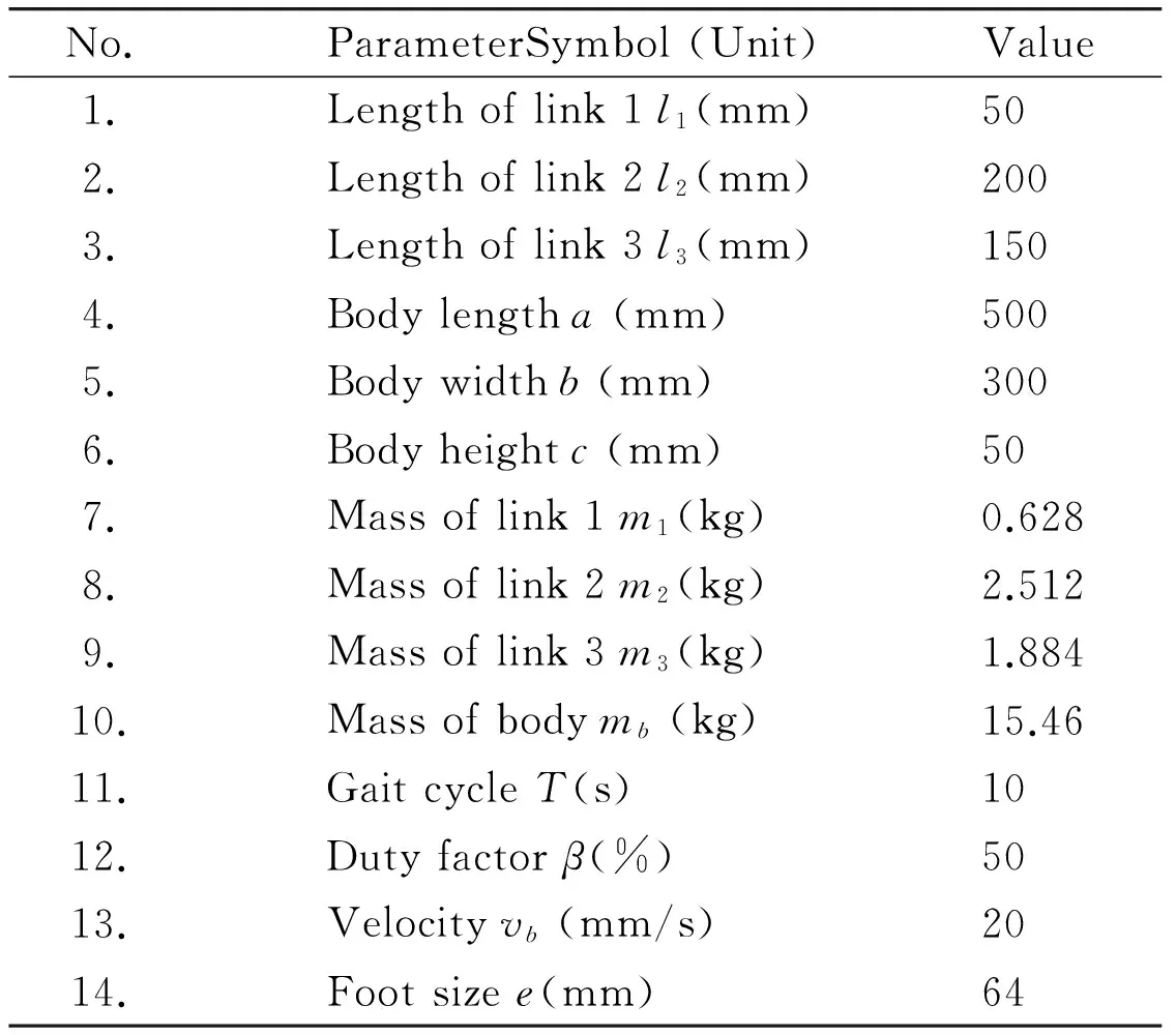
Table 3 The parameters of robot
According to the structure parameters of the robot, the maximum gait parameters of the robot can be determined. The maximum step lengthSmax is 245mm, and the maximum step heightHmax is 120mm.
5.1 Step length
The quadruped robot walks on the slop with trot gait. Set the slop angle to 20°, and the step heightHat 50mm. Step lengthSincreases from 100mm to 140mm, ZMP offset distancedchanges with step lengthSduring one step cycle, as shown in Fig.7.
The stability of the quadruped robot decreases with the increase of step length. When the step length is 136mm, the ZMP offset distance is 44mm, which is less than the maximum offset distance. The robot can keep stable.
When the slope angle is 20°, and the step height is 50mm, the step length should be less than 136mm to keep the robot stable.

Fig.7 d change with the step length
5.2 Step height
The quadruped robot walks on the slop with trot gait. Set the slop angle to 20°, and step lengthSat 100mm. When step heightHincreases from 40mm to 120mm, offset distancedchanges with step heightHduring one step cycle, as shown in Fig.8.
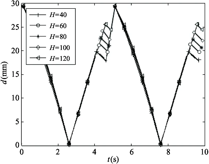
Fig.8 d change with step height
(1) The step length keeps invariable, the stability of the quadruped robot decreases with the increase of the step height.
(2) Compared with the step length, the step height has less influence on the stability.
5.3 Slope angle
The quadruped robot walks on the slop with trot gait. Set the step height at 50mm, and the step lengthSat 100mm. When the slope angle increases from 15° to 40°, ZMP offset distancedchanges with the slope angle during one step cycle, as shown in Fig.9.
The quadruped robot walks on the slope with trot gait, the stability of the quadruped robot decreases with the slope angle increase. When the slope angle is 30°, the ZMP offset distance is 44mm, which is less than the maximum offset distance 45mm. The robot can keep stable. Otherwise, the robot is unstable.
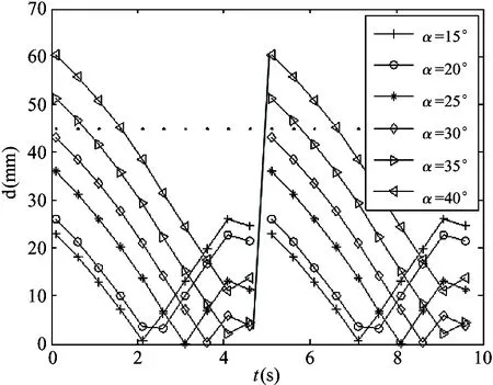
Fig.9 d change with slop angle
So the quadruped robot walks on the slope with trot gait, the step height is 50mm, and the step length is 100mm, the slope angle should be less than 30°.
It is concluded that:
(1) The step length keeps invariable, the stability of the quadruped robot decreases with the increase of the step height. But compared with the step length, step height has less influence on the stability.
(2) The step height keeps invariable, the stability of the quadruped robot decreases with the step length. If the slope angle is 20°, and the step height is 50mm, the step length should be less than 136mm to keep the robot stable.
(3) If the step length is 100mm, and the step height is 50mm, the slope angle should be less than 30° to keep the robot stable.
6 Simulation
The simulation of the quadruped robot walking on slope with trot gait was performed in software ADAMs.
The virtual prototype model was established in software Solid-works, and inputted into the ADAMs. Each joint was added the angular velocity driving function, which is determined by the inverse kinematics. The contact constraint was added between the feet in supporting phase and environment.
(11)
where k is stiffness coefficient depending on the material properties,k=1000kN/mpk, δ is penetration depth of the foot into the ground, pkis exponent of the penetration for the normal elastic force, pk=2.2. and pdis exponent of the penetration for the normal damping contact force, pd=0.5.
6.1 Simulation in ADAMS software
Simulations were performed with different gait parameters and different slope angles. The simulation sequence chart of quadruped robot walking on slop is shown in Fig.10.
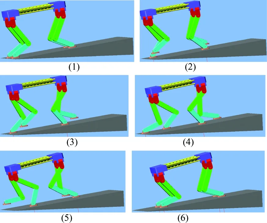
Fig.10 The sequence chart
6.2 Simulation results
Set the slop angle at 10°, step length at 100mm and step height at 60mm, gait cycle at 10s.The simulation results of foot trajectory and COG were obtained, as shown in Fig.11.

(a) Foot displacement of 1th and 3th leg along z direction
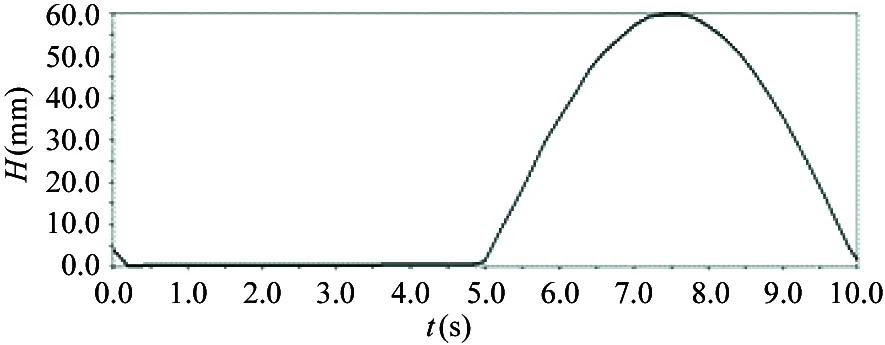
(b) Foot displacement of 2th and 4th leg along z direction
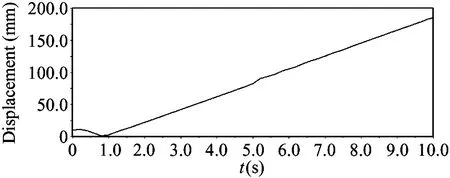
(c) COG displacement
7 Conclusions
In this study, dynamic stability of the quadruped robot walking on slope with trot gait was analyzed. The sinusoidal function was planned as the foot trajectory function. The vertical distance from ZMP to the supporting diagonal line was defined as the ZMP offset distanced. The vertical distance between the supporting diagonal line and the boundary of the supporting polygon was defined as the maximum offset distance Δ. Whetherdis less than Δ or not, it was used as the dynamic stability criterion. The slope angle and the gait parameters influence the stability. When the slope angle keeps invariable, the stability of the quadruped robot decreases with the step length and step height increase. The step length influences the stability more than that of step height. When the gait parameters keep invariable, the stability decreases with the slope angle increase. Finally, simulations were performed to verify the theoretical analysis.
The experiment of robot walking on slope will be conducted in the future. The optimal posture angle will be determined by the experiment, and the control algorithm for dynamic stable walking on slop will be evaluated.
[ 1] Arikawa K, Hirose S. Development of quadruped walking robot TITAN-VIII. In: Proceedings of the IEEE/RSJ International Conference on Intelligent Robots and Systems, Osaka , Japan,1996. 208-214
[ 2] Mrinal K, Jonas B, Peter P, et al. Fast, robust quadruped locomotion over challenging terrain. In: Proceedings of the IEEE International Conference on Robotics and Automation Anchorage Convention District, Anchorage, USA, 2010. 2665-2670
[ 3] Zhang S, Gao J, Duan X, et al. Trot pattern generation for quadruped robot based on the ZMP stability margin. In: Proceedings of the International Conference on Complex Medical Engineering, Beijing, China, 2013. 608-613
[ 4] Lee J H, Park J H. Control for quadruped robots in trotting on horizontal and slanted surfaces. In: Proceedings of the IEEE 9th Asian Control Conference (ASCC), Istanbul, Turkey, 2013. 1-6
[ 5] Chatzakos P, Papadopoulos E. Dynamically running quadrupeds self-stable region expansion by mechanical design. In: Proceedings of the IEEE International Conference on Robotics and Automation, Kobe, Japan. 2009. 2749-2754
[ 6] Kim B H. Centroid-based analysis of quadruped-robot walking balance. In: Proceedings of the International Conference on Advanced Robotics, Munich, Germany, 2009. 1-6
[ 7] Pongas D, Mistry M, Schaal S. A robust quadruped walking gait for traversing rough terrain. In: Proceedings of the IEEE International Conference on Robotics and Automation, Roma, Italy, 2007. 1474-1479
[ 8] Reza Y, Vahid J M, Reza O. Dynamically stable trajectory planning for a quadruped robot. In: Proceedings of the 20th Iranian Conference on Electrical Engineering, Tehran, Iran, 2012. 845-850
[ 9] Meek S, Kim J, Anderson M. Stability of a trotting quadruped robot with passive, underactuated legs. In: Proceedings of the IEEE International Conference on Robotics and Automation (ICRA), Pasadena, USA, 2008. 347-351
[10] Zhang L, Ma S G, Honda Y, et al. Omni-directional walking of a quadruped robot on a slope. In: Proceedings of the IEEE International Conference on Robotics and Biomimetics, Shenyang, China, 2004. 268-273
[11] Wang P, Huang B, Sun L. Stability judging method for quadruped bionic robot.JournalofharbinInstituteoftechnology,2008, 4(7):1063-1066
[12] Shibendu S R, Dilip K P. Effects of turning gait parameters on energy consumption and stability of a six-legged walking robot.RoboticsandAutonomousSystems, 2012, 60(1): 72-82
[13] Zhang L, Wang L L, Ma S G. Research of a quadruped robot walking on a slope based on 4-legsupporting period. In: Proceedings of the IEEE International Conference on Robotics and Biomimetics, Tianjin, China, 2010. 1346-1351
[14] Lei J T, Wang F, Yu H Y, et al. Energy efficiency analysis of quadruped robot with trot gait and combined cycloid foot trajectory.ChineseJournalofMechanicalEngineering, 2014, 27(1):138-145
Lei Jingtao, born in 1970. She received her Ph.D degrees from Beihang University in 2007. She also received her B.S. and M.S. degrees from Henan University of Science and Technology in 1991 and 1996 respectively. Her research interests include the robot mechanisms and robot modular technology.
10.3772/j.issn.1006-6748.2016.01.001
① Supported by the National Natural Science Foundation of China (No. 51375289), Shanghai Municipal National Natural Science Foundation of China (No.13ZR1415500) and Innovation Fund of Shanghai Education Commission (No.13YZ020).
② To whom correspondence should be addressed. E-mail: jtlei2000@163.comReceived on Jan. 22, 2015
 High Technology Letters2016年1期
- High Technology Letters的其它文章
- Mixing matrix estimation of underdetermined blind source separation based on the linear aggregation characteristic of observation signals①
- An improved potential field method for mobile robot navigation①
- Robust SLAM using square-root cubature Kalman filter and Huber’s GM-estimator①
- Time difference based measurement of ultrasonic cavitations in wastewater treatment①
- Research on the adaptive hybrid search tree anti-collision algorithm in RFID system①
- Selective transmission and channel estimation in massive MIMO systems①
