An improved potential field method for mobile robot navigation①
Li Guangsheng (李广胜), Chou Wusheng
(Robotics Institute, Beijing University of Aeronautics and Astronautics, Beijing 100191, P.R.China)
An improved potential field method for mobile robot navigation①
Li Guangsheng (李广胜)②, Chou Wusheng
(Robotics Institute, Beijing University of Aeronautics and Astronautics, Beijing 100191, P.R.China)
In order to overcome the inherent oscillation problem of potential field methods (PFMs) for autonomous mobile robots in the presence of obstacles and in narrow passages, an enhanced potential field method that integrates Levenberg-Marquardt (L-M) algorithm and k-trajectory algorithm into the basic PFMs is proposed and simulated. At first, the mobile robot navigation function based on the basic PFMs is established by choosing Gaussian model. Then, the oscillation problem of the navigation function is investigated when a mobile robot nears obstacles and passes through a long and narrow passage, which can cause large computation cost and system instability. At last, the L-M algorithm is adopted to modify the search direction of the navigation function for alleviating the oscillation, while the k-trajectory algorithm is applied to further smooth trajectories. By a series of comparative experiments, the use of the L-M algorithm and k-trajectory algorithm can greatly improve the system performance with the advantages of reducing task completion time and achieving smooth trajectories.
potential field, oscillation, Gaussian model, Levenberg-Marquardt (L-M) algorithm, k-trajectory
0 Introduction
With the continuous development of robot technology, the widespread use of autonomous mobile robot will become an inevitable trend, especially in severe environment not suitable for humans to access for working operations, such as daily maintenance of nuclear power plants in high radiation areas. The using of autonomous mobile robots in practice will greatly improve the production efficiency and reduce labor intensity.
Research on autonomous navigation is an imperative task required in autonomous mobile robot applications. Over the years, a great number of methods that deal with the autonomous navigation problems have been done in this field. Usually, one of the most general and simple ways to develop the navigation is based on potential field method (PFM). This approach was first introduced by Khatib[1], who defined negative electric charge and positive electric charge around the goal and obstacle respectively. The positive charge generates a virtual force that repels the mobile robot from obstacle, while the negative charge creates a virtual force that attracts the mobile robot to the target. Hereafter, many researchers introduced new methods based on this principle to improve the performance of PFM, such as Volpe presented a new potential field based on the modified ellipses model[2], and Khosla proposed a new superquadric potential field model for obstacle avoidance[3]. However, those approaches have some inherent drawbacks. In Ref.[4], Koren and Borenstein identified the significant problems of PFM. In order to overcome the problem of oscillation, on one hand, Sato[5]introduced a motion planning method to prevent the formation of local minima, which was based on Laplace potential field and had no minimal point. In Ref.[6], Zou proposed a novel navigation algorithm by using virtual local goals to replace the global objective for escaping the local minimum when the mobile robot trapped in local minima. Zhang and Duan[7]proposed a modified artificial physics method to alleviate oscillation by using gravitational model. On the other hand, Jing[8]proposed artificial coordinating fields to deal with the problems of mobile robots being in uncertain dynamic environments with obstacles. Kenneth, et al.[9-11]adopted a modified Newton’s method (MNM) based on the Gaussian model to choose Newton direction for the navigation function rather than using the gradient descent direction.
In this work, the Levenberg-Marquardt method (L-MM) is adopted to modify Newton direction for alleviating the oscillation problem of the PFM based on Gaussian model, and k-trajectory method is used for smoothing trajectories. From the viewpoint of optimization, L-MM is an iterative technique, which has the advantages of fast convergence rate, and can be used for solving nonlinear least squares problems[12]. Therefore, by using the L-MM and k-trajectory algorithm in combination, the enhanced potential field method (EPFM) can achieve a good approximation to the navigation function. The simulation results show that the mobile robot can accomplish obstacle avoidance and target searching in the environment with a complex configuration of target and obstacles, and EPFM can greatly alleviate oscillation and achieve smoother trajectories.
This paper is organized as follows. In Section 1, the basic PFM and its inherent oscillation phenomenon are introduced. In Section 2, a detailed instruction about the L-M algorithm and k-trajectory algorithm are provided. In Section 3, a series of performance comparison experiments for the basic PFM, MNM and EPFM with different potential models are performed, and then the simulation results are presented and analyzed. In Section 4, a brief conclusion and further researches are provided.
1 Basic potential field method and inherent oscillation phenomenon
1.1 Basic potential field method model
In the basic PFM, obstacles and the targets or the goals are all considered as point mass. For building potential field, in this section, Gaussian model and Gaussian-like model are chosen to establish the attractive force function and the repulsive force function in two dimensions, respectively. The target is defined as the attractive point, whose position of the center of the mass is represented by vector qa(ax, ay). Similarly, vector qr(rx, ry) is defined as the position of repulsive point, such as obstacle or other robot. The mobile robot is located at q(x, y).
The attractive force function represented by the negative Gaussian model is defined as
(1)
The repulsive force function is expressed as
(2)

Fig.1 displays the effect of adjusting the parameterCand varianceρon the repulsive force function.
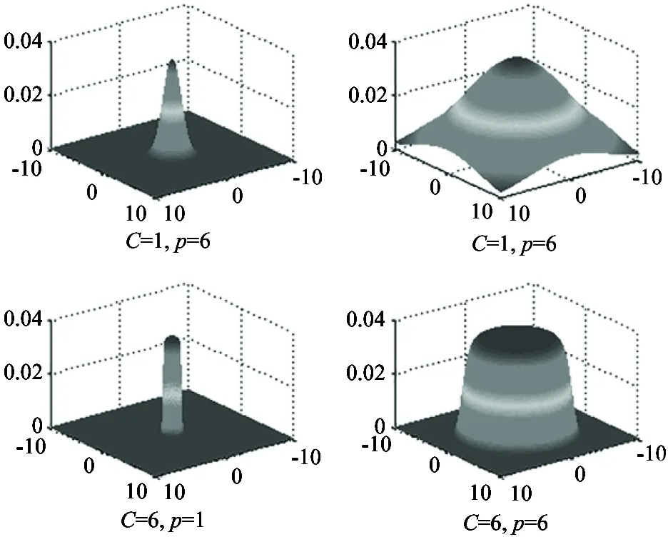
Fig.1 The effect of the parameters C and variance ρ
From Fig.1, it can be deduced that the implement adjustments of affecting range and affecting area of attractive force and repulsive force are feasible by adjusting the value of parameterCandρ. Since the parameters can be controlled easily, thus, the Gaussian model is chosen to establish the autonomous navigation function for mobile robot.
1.2 Control law of mobile robot navigation
To facilitate the discussion, it is assumed that there is only one target in an initially unknown environment. The navigation function that drives the mobile robot moving toward the goal is given by
F(q)=FA(q)+FR(q)
(3)
where F(q) is the sum of the forces that effects the mobile robot. FA(q) represents the attractive force between the target and mobile robot, FR(q) denotes the sum of repulsive forces generated by a set of obstacles.
Using the navigation function defined above, the control law of mobile robot navigation is then given by
(4)
1.3 Path generation for mobile robot
Based on the control law above, the forces acting upon the mobile robot can drive it moving toward the predetermined target along the gradient descent direction within the maximum speed.
In the process of the moving, a series of feasible path solutions can be obtained as the step (current solution) going on until getting the target, which can be labelled with Pi(xi, yi, zi). By connecting the solution Piin sequence, therefore, the mobile robot path can be described as
Path={P0, P1(x1, y1, z1),
P2(x1, y1, z1),…,Pn}
(5)
where P0is the start point, and Pnis the target point.
1.4 The PFM inherent oscillation phenomenon
In practical applications, however, the PFM has some inherent flaws that happen quite frequently, such as trapped with local minima, no passage among closely spaced obstacles, and oscillation in the vicinity of obstacles and in a narrow passage[4]. The most serious problem is oscillation phenomenon, whose causes are not only closely related to unstable motions derived from instability of the discrete system resulting from sampling of sensory inputs, but also related to the stable oscillatory gradient trajectory[10]due to the rapid changes in direction. In this paper, it is assumed that the sensors are capable of achieving the relative position of obstacles and target, and the discrete navigation system of the mobile robot is in a stable running. So our interest is mainly restricted to the substantial reasons of oscillation problem from the theoretical perspective.
From the perspective of optimization theory, PFM is inherently associated with the oscillation problem. As a result of using the orthogonal search direction, the trajectory exhibits strong zigzagging phenomenon when the mobile robot nears obstacles. Furthermore, PFM can only contain linear information and achieve linear convergence rate. So it cannot provide a better approximation to the potential field navigation function in the process of iterative calculation, especially when the navigation function becomes a nonlinear function due to the complex configuration of target and obstacles. One solution is to use optimization theory to overcome the oscillation problem by introducing higher order information to approximate the navigation function.
Fig.2 shows the oscillation phenomenon by using the basic PFM.
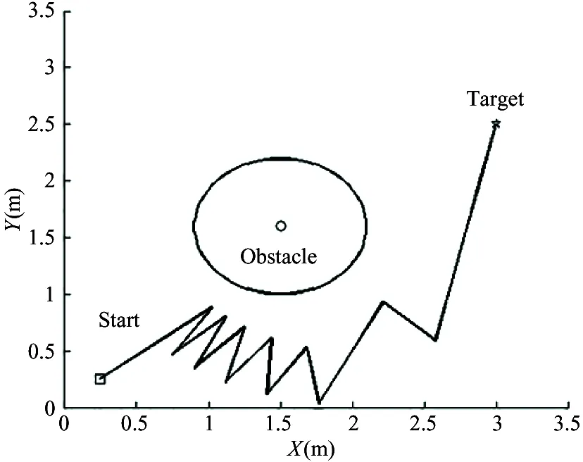
Fig.2 Illustration of the oscillation phenomenon
2 The improved potential field method
2.1 Levenberg-Marquardt algorithm for oscillation
To solve the oscillation problem of PFM, the use of the L-M algorithm is proposed to establish the mobile robot navigation function. This method can find the most suitable direction, the modified Newton direction, which contains both the first and second derivative information. Compared with other existing methods, such as the steepest descent method (SDM), EPFM has the second order accuracy approximation ability to the navigation function with at least second order convergence rate. Thus, it is viable to modify the Newton direction by using L-M algorithm, and adopt the modified Newton direction as the search direction of the navigation function.
The dynamics of the mobile robot is given by the control law:
(6)
In Eq.(6), B(q) is a positive definite matrix. As in the optimization theory, B(q) is defined as
B(q)=(G(q)+μk(q)I)-1
(7)
where μkis referred to as the damping coefficient, which is only related to q(x, y) and should satisfy the condition of μk>0. The presence of μkthat can guarantee the matrix B(q) is invertible. G(q) is the Hessian matrix of F(q), which is defined as
(8)
According to the optimization theory, the kernel operation of the L-M algorithm can dynamically adjust the value of parameter μkin its iterative process. When the current position of the mobile robot is far away from the obstacles or target, the value of parameter μkshould be adjusted smaller. Otherwise, the value of parameter μkshould be adjusted larger. In the practical applications of L-M method, it is common to take the strategy to adjust parameter μk, which is similar to trust region method.
The L-M algorithm process is shown in Table 1.
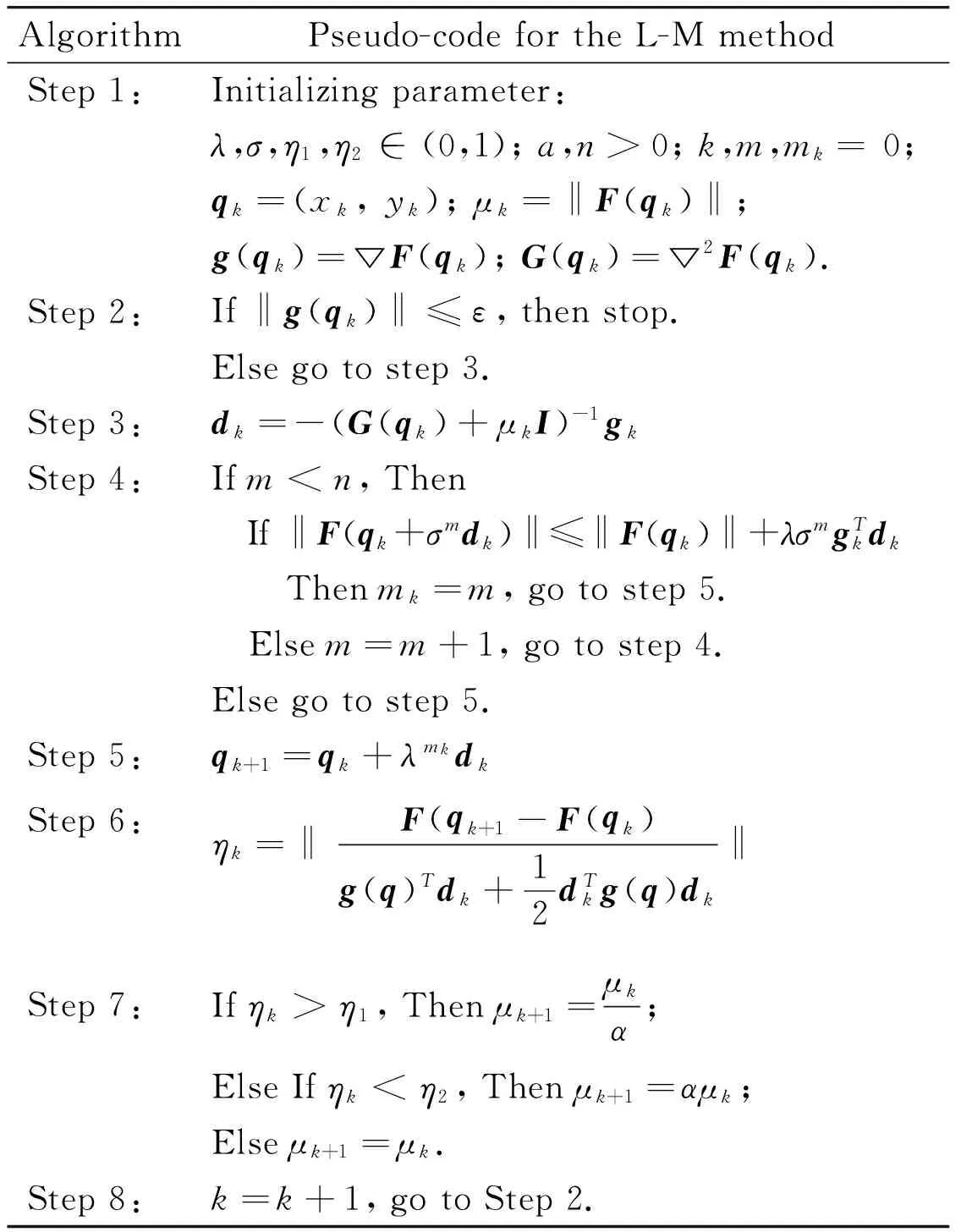
Table 1 The L-M algorithm process
2.2 K-trajectory for path smoothing
The mobile robot original path generated by the improved method based on combining PFM with L-M algorithm is usually hard for exact moving. There are some turning points on the original path, which have great deviation of turning angle, tending to case a large amount of oscillation. In this section, a feasible strategy called k-trajectory is adopted to smooth the unoptimized trajectories[14].
Assume that the mobile robot path consists of a ordered set of waypoints, and wi-1, wiand wi+1are the any three continuous waypoint of it. The unit vectors along the corresponding path segments are defined as
qi=(wi-wi-1)/‖wi-1-wi‖
(9)
qi+1=(wi+1-wi)/‖wi+1-wi‖
(10)
where angle β between qiand qi+1is expressed as
(11)
From Fig.3, the expression can also be obtained as follows:
(12)

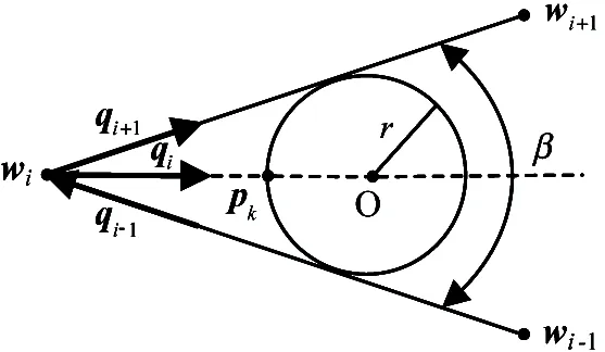
Fig.3 Graphical depiction of the k-trajectory
Therefore, the point pkcan be expressed by
(13)
After this process, the original path formed by wi-1, wiand wi+1could be replaced by the circular arc and the line segments, which is represented by the solid line in Fig.4.
3 Results and comparison
In order to validate EPFM, simulation experiments have been performed on industrial PC (Intel i5, 2.50GHz, 4GB memory), the operating system is Windows8 with Matlab (2012a) software. In the course of processing, there are no any commercial algorithm tools used.
To analysy the results more intuitively, the following evaluation criteria are adopted to evaluate the performance of the mobile robot:
(1) How many steps the mobile robot reaches the target.
(2) The smoothness of the trajectory.
For all scenarios, the parameters of EPFM are set as follows:C=10,ρ=3,λ=0.55,σ=0.4,ε=1e-6,η1=0.75,η2=0.25,n=20,α=10.
3.1 Applying the EPFM to different potential models
According to the theory of optimization, oscillation occurring is not only closely connected with the complex configuration of target and obstacles, but also depends greatly on the potential field model chosen to construct the navigation function F(q). In this section, the SDM, MNM and EPFM that use different models (generalized Gaussian model, parabolic model, and generalized gravitational model) to construct F(q) for the mobile robot were compared in a typical obstacle avoidance and target reaching task. The corresponding results are shown in Figs 5~7.
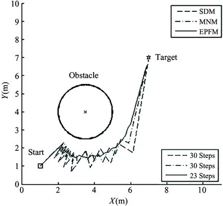
Fig.6 Performance comparisons of the three methods using parabolic model
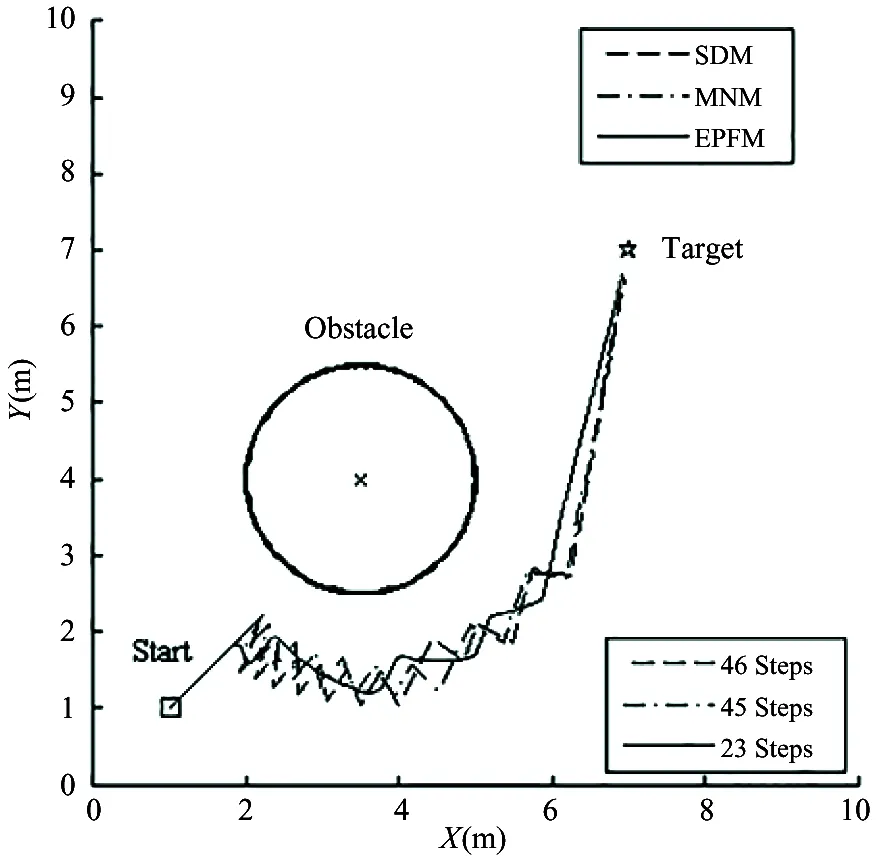
Fig.7 Performance comparisons of the three methods using gravitational model
Figs 5~7 show the corresponding trajectories, and the average numbers of steps spent by the mobile robot for succeeding in avoiding obstacles and seeking target via using different methods in each scenario. From those typical examples, it can be found that the EPFM can better achieve smoother trajectories and faster progress compared to the other methods mentioned above.
3.2 Performance in passing a randomly generated obstacle area of different shapes
In this section, a series of obstacles with different sizes and shapes are randomly generated to represent a random, complex and unknown environment in an area of 100m×120m. Moreover, the minimum distance between any two obstacles is specified to make sure that the mobile robot can pass through the passage among obstacles. The mobile robot starts from the point of (10,10) and is required to reach the target at (90,80).
Fig.8 shows the trajectories corresponding to the three methods.
In Fig.8, it can be seen that although all the methods can successfully reach the target, the EPFM and MNM can make trajectories smoother compared to the SDM, since trajectories obtained by SDM have a great quantity of oscillation when obstacles are nearby. From Fig.8, it can also be concluded that EPFM can achieve the target with fewer steps compared to SDM and MNM.
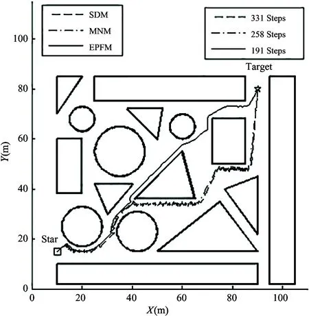
Fig.8 Performance comparisons of the three methods through a randomly generated obstacle area of different shapes
3.3 Passing through a long and narrow passage
In practical applications, oscillation frequently occurs when the mobile robot passes through long and narrow corridors. To illustrate this problem, SDM and EPFM are tested on the tasks of traveling in a wide and a narrow passage.
In Fig.9(a) and (b), it can be seen that both the SDM and EPFM can drive the mobile robot to pass through the passage fast and keep smooth trajectories when the width of the corridor is 2m. In the Fig.9(c) and (d), however, when the passage width is narrowed down to 1m, serious oscillation appear to the trajectory based on the SDM due to the sudden change of the passage width, while EPFM can still make the robot quickly move to target in fewer steps with smooth trajectory.
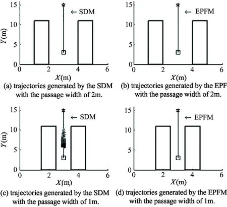
Fig.9 Performance comparisons of the SDM and EPFM through a long and narrow passage
The simulation results also prove that oscillation occurring does not depend on the obstacle shapes in PFM applications.
3.4 Performance in real environment
To further demonstrate the performance of the proposed method in practical applications, experiments have been conducted under outdoor environment.
Fig.10 shows the mobile robot used in the experiments, which is an omnidirectional mobile robot. It has a global position system (GPS) and 10 ultrasonic sensors to get the knowledge of their information about the orientation and location (the absolute position and the relative position), and its maximum speed is 2m/s.
Fig.11(a) shows the experimental environment with a rectangular obstacle, and the trajectories responding to the three methods are plotted in Fig.11(b). Fig.12 shows the parts of the enlarged versions in Fig.11(b).

Fig.10 The robot for experiments
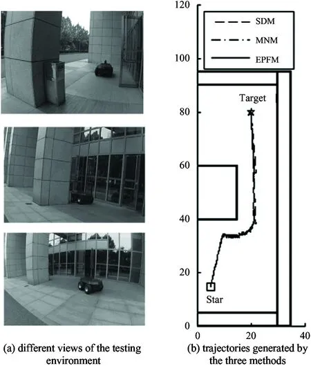
Fig.11 Experiments with a real mobile robot
From Fig.11 and Fig.12, it can be seen that a large amount of oscillation exists in the trajectories obtained by PFM and MNM, while the EPFM can provide a smoother trajectory.
Moreover, the turning angles of the three methods can also be obtained in the practical experiments. Therefore, the deviation of the turning angle can be introduced to evaluate the smoothness of the trajectory since the smoother trajectory has a smaller deviation of turning angle. Fig.13 shows the deviation response for the three methods. It can be concluded that the use of the EPFM can keep a more smoother trajectory without frequent turning compared to the SDM and MNM.
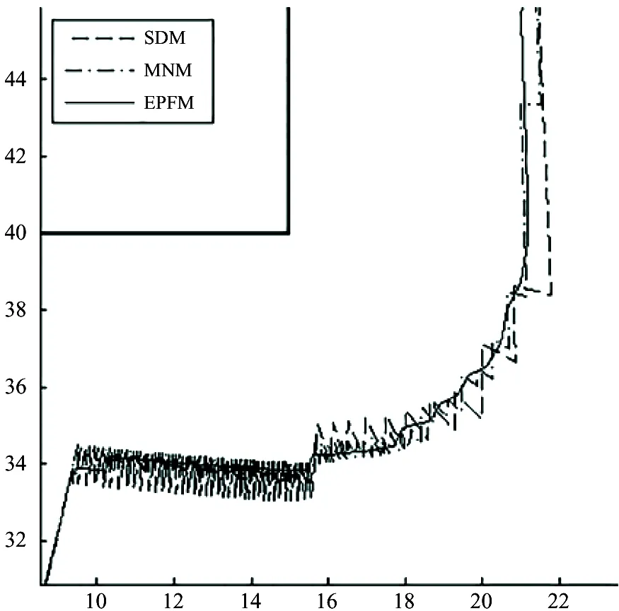
Fig.12 Parts of enlarged version of Fig. 11 (b)

Fig.13 The turnning angles response for the three methods
4 Conclusion
This study proposes an enhanced PFM, which integrates L-M algorithm and k-trajectory algorithm into the basic PFM, to overcome the oscillation problem of the mobile robot navigation in a complicated environment with obstacles. A series of comparative experiments have been carried out to demonstrate the proposed approach in various scenarios with different models and methods. The results show that the proposed method can greatly improve the overall system performance. Compared with the basic PFM and the MNM, the EPFM has shown the capability of alleviating the oscillation and consuming much fewer time steps. As a result of the significant improvement in the steps, a real-time application of the proposed approach in dynamic mobile robot navigation becomes possible.
[ 1] Khatib O. Real-time obstacle avoidance for manipulators and mobile robots.InternationalJournalofRoboticsResearch, 1985, 5(1): 90-98
[ 2] Volpe R, Khosla P. Artificial potentials with elliptical isopotential contours for obstacle avoidance. In: Proceedings of the 26th IEEE Conference on Decision and Control, Los Angeles, USA, 1987. 180-185
[ 3] Khosla P, Volpe R. Superquadric artificial potentials for obstacle avoidance and approach. In: Proceedings of the 1988 IEEE International Conference on Robotics and Automation, Philadelphia, USA, 1988. 1778-1784
[ 4] Koren Y, Borenstein J. Potential field methods and their inherent limitations for mobile robot navigation. In: Proceedings of the 1991 IEEE International Conference on Robotics and Automation, Sacramento, USA, 1991. 1398-1404
[ 5] Sato K. Deadlock-free motion planning using the Laplace potential field.AdvancedRobotics, 2012, 7(5): 449-461
[ 6] Zou X Y, Zhu J. Virtual local target method for avoiding local minimum in potential field based robot navigation.JournalofZhejiangUniversity(science), 2003, 4(3): 264-269
[ 7] Zhang X Y, Duan H B, Luo Q N. Levenberg-Marquardt based artificial physics method for mobile robot oscillation alleviation.ScienceChinaPhysicsMechanics&Astronomy, 2014, 57(9): 1771-1777
[ 8] Jing X J, Wang Y C, Tan D L. Artificial coordinating field and its application to motion planning of robots in uncertain dynamic environments.ScienceinChina, 2004, 47(5): 577-594
[ 9] McIsaac K A, Ren J, Huang X S. Modified Newton’s method applied to potential field navigation. In: Proceedings of the 42nd IEEE Conference on Decision and Control, Maui, Hawaii, USA, 2003. 5873-5878
[10] Ren J, McIsaac K A, Patel R V. Modified Newton’s method applied to potential field-based navigation for mobile robots.IEEETransactionsonRobotics, 2006, 22(2): 384-391
[11] Ren J, McIsaac K A, Patel R V. Modified Newton’s method applied to potential field-based navigation for nonholonomic robots in dynamic environments.Robotica, 2008, 26(1): 117-127
[12] Lourakis M I A. A brief description of the Levenberg-Marquardt algorithm implemened by levmar. http://www.ics.forth.gr/~lourakis/levmar/: Foundation of Research & Technology-Hellas, 2005
[13] Ren J, McIsaac K A. A hybrid-systems approach to potential field navigation for a multi-robot team. In: Proceedings of the 2003 IEEE International Conference on Robotics and Automation, Taipei, China, 2003. 3875-3880
[14] Anderson E P, Beard R W, McLain T W. Real-time dynamic trajectory smoothing for unmanned air vehicles.IEEETransactionsonControlSystemsTechnology, 2005, 13(3): 471-477
Li Guangsheng, born in 1985. He received his B.S. and M.S. degrees in Mechatronics Engineering in 2010 and 2013 respectively. And currently he is pursuing the Ph.D. degree of Mechatronic Engineering in Beihang University. His current research interest is embedded control of robots.
10.3772/j.issn.1006-6748.2016.01.003
① Supported by the National Key Basic Research Program of China (973 Project) (No.2013CB035503).
② To whom correspondence should be addressed. E-mail: liguangsheng10@163.comReceived on Mar. 25, 2015
 High Technology Letters2016年1期
- High Technology Letters的其它文章
- Mixing matrix estimation of underdetermined blind source separation based on the linear aggregation characteristic of observation signals①
- Research on the adaptive hybrid search tree anti-collision algorithm in RFID system①
- Robust SLAM using square-root cubature Kalman filter and Huber’s GM-estimator①
- Time difference based measurement of ultrasonic cavitations in wastewater treatment①
- CSMCCVA: Framework of cross-modal semantic mapping based on cognitive computing of visual and auditory sensations①
- Selective transmission and channel estimation in massive MIMO systems①
