Modeling and simulation of bow wave effect in probe and drogue aerial refueling
Dai Xunhua,Wei Zibo,Quan Quan
School of Automation Science and Electrical Engineering,Beihang University,Beijing 100083,China
Modeling and simulation of bow wave effect in probe and drogue aerial refueling
Dai Xunhua*,Wei Zibo,Quan Quan
School of Automation Science and Electrical Engineering,Beihang University,Beijing 100083,China
Aerial refueling;Aerodynamic;Bow wave;Modeling;Probe and drogue;UAV
In a probe and drogue aerial refueling system,the bow wave of the receiver aircraft will produce a strong aerodynamic effect on the drogue once the receiver follows the drogue at a close distance.It is a major difficulty of docking control in the probe and drogue refueling.This paper analyses the bow wave effect and presents a simple method to model it.Firstly,the inviscid flow around the receiver is modeled based on the stream function defined by basic stream singularities.Secondly,a correction function is developed to eliminate the error caused by the absence of air viscosity.Then,the aerodynamic coefficients are used to calculate the induced aerodynamic force on the drogue.The obtained model is in an analytical form that can be easily applied to the controller design and the real-time simulations.In the verification part,computational fluid dynamics(CFD)simulation tests are conducted to validate the obtained flow fields and aerodynamic forces.Finally,the modeling method is applied to an F-16 receiver aircraft in a previously developed autonomous aerial refueling simulation system.The simulations results are analyzed and compared with the NASA flight-test data,which demonstrates the effectiveness of the proposed method.
1.Introduction
Aerial refueling has demonstrated great benefits to aviation by increasing an aircraft’s effectiveness through extending its range and endurance.1Recently,the development of unmanned aerial vehicles(UAVs)has pioneered a new realm for the application of aerial refueling and the developments of autonomous aerial refueling(AAR)techniques for UAVs make new missions and capabilities possible,like the ability to remain on station for days or even weeks.2
Currently,there are two major types of aerial refueling in operation:probe-drogue refueling(PDR)and boomreceptacle refueling(BRR),3and both of them play important roles in modern civil and military applications.PDR systems are considered simpler and more flexible than BRR systems,because PDR systems can be adapted to various refueling speeds and multiple receiver aircraft.4However,the significant drawback of PDR is that the drogue is completely passive and susceptible to the aerodynamic influence from multiple aspects,including the wind effect from the tanker,the receiver and the atmospheric disturbance.5,6
The wind effect from the receiver aircraft is generally referred to as the forebody effect2or the bow wave effect7.As shown in Fig.1,a strong bow wave induced by the forebody of the receiver will change the flow field that the drogue is exposed to,and the forebody flow field tends to push the drogue away when they are close to each other(within few meters).Since the drogue is more flexible than the receiver,precise control is a tough task.In manned refueling procedures,experienced pilots can accomplish the refueling mission by carefully anticipating the movement of the drogue.However,it is still difficult for unmanned aerial refueling.NASA performed the first unmanned aerial refueling test in 2006,where only two out of six capture attempts succeed due to‘‘the drogue is pushed upward by the forebody flow field of the receiver”2and they named it the ‘‘forebody effect”.2
So far,the wind effects from the tanker and atmospheric disturbance have already been well studied as presented in Ref.8,but the bow wave effect has yet received very little attention.NASA performed flight tests to find ways to estimate the range of the bow wave effect in Ref.9.In recent years,numerical models10,11were developed based on the look-up tables obtained by computational fluid dynamics(CFD)simulations.In 2014,a CFD-simulation analysis was carried out by Khan and Masud12to find the optimal initial location of the refueling basket such that the forebody flow field has minimal aerodynamic effects on the drogue.However,the procedures to obtain data by CFD simulations are very complex and highly time-consuming.Moreover,the numerical models are inconvenient for the controller design.In Ref.13,an analytical model based on the stream function was developed for BRR,but the model is only available to the specific aircraft and it is not suitable for PDR.
In this paper,a method to model the bow wave effect in PDR is developed.Firstly,the inviscid flow around the receiver is modeled based on the stream function defined by basic stream singularities.Secondly,a correction function is developed to eliminate the error caused by the absence of air viscosity.Then,the aerodynamic coefficients are used to calculate the induced aerodynamic force on the drogue.Finally,the obtained aerodynamic force is incorporated into a hosedrogue dynamic model to simulate the drogue movement under the bow wave effect.The contributions of this paper are as follows:(1)a simple and analytical model of the bow wave effect for PDR is proposed for the first time,which is easily applied to the controller design and the real-time simulations;(2)the proposed method is flexible,which is applicable to difference refueling conditions,such as different altitudes,speeds,or different types of drogues.
The paper is organized as follows.Section 2 gives a comprehensive mathematical analysis of the bow wave effect.Section 3 describes the procedures to obtain the forebody flow field of the receiver.Section 4 introduces the method to obtain the aerodynamic force of the drogue under the effect of the induced flow field.To validate the proposed method,comparisons with the results from the CFD simulation and the NASA flight test are made in Section 5,which indicates that the modeling method is effective and practical.Finally,Section 6 presents the conclusions and future work.
2.Problem formulation
2.1.Frames and notations
The overview diagram of the PDR system is presented in Fig.2.There are two major frames used in this paper:the tanker wind reference frameTW(OTWxTWyTWzTW)and the receiver nose frameRN(ORNxRNyRNzRN),whereOTWis the origin of frameTWwhich is fixed to the conjunctive point between the tanker body and the hose,and the direction ofOTWxTWis aligned with the wind frame of the tanker which is also parallel to the free stream velocityV∞(V∞is equal and opposite to the tanker airspeedVT).The origin ofRNis fixed to the tip of the receiver nose,and the axes ofRNare aligned withTW.The ground inertial frameI(OIxIyIzI)is a north-east-down(NED)system andRB(ORBxRByRBzRB)is defined as the body frame of the receiver aircraft whose origin is at the center of the aircraft and axes aligned with aircraft reference directions(nose-right-down).14The drogue body frameDB(Oxyz)is defined the same way asRB,whose origin is located at the center of the drogue and axes are aligned with the symmetric axes of the drogue(see Fig.2).pdrand pprare relative positions of drogue and probe.
Rules of defining notations for the frame description and transformation are made in this paper:
A right superscript on a vector will specify the frame that the vector is defined.
The rotation matrix from frameBto frameAwill be denoted by RA/B.For example,pRdrNdenotes the position of drogue pdrdefined in the frameRN,and RTW/RNdenotes the rotation matrix fromRNto frameTW.
Two assumptions can be made for the simplification of the bow wave effect model:
Assumption 1.αR,βRare small,and let αR=0°,βR=0°.
Assumption 2.RTW/DB=RTW/RN=RTW/RB=I3.
Remark 1.Considering that the angle of attack of the receiver αRis generally small(0°< αR< 10°)during the capture stage,and only a small region around the forebody of the receiver aircraft(with length about 2 m from the tip)is concerned,the existence of αRwill have insignificant effect on the calculation of the induced velocity field.So,it is reasonable to assume that the angle of attack of the receiver αR=0°.For the same reason,the angle of sideslip of the receiver βRis assumed to be zero.Under Assumption 1,the body frame and wind frame of the receiver will have the same direction,and then the complex steps for coordinate transformations can be omitted.
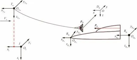
Fig.2 Overview diagram of the PDR system.
Remark 2.Obviously,according to the definitions ofTWandRN,it obtains that RTW/RN=I3.Then according to Assumption 1,RTW/RB=I3.In addition,the strong air-drag produced by the high speed wind will keep the drogue axis parallel to the direction of the free stream,which indicates RTW/DB=I3.
Remark 3.The obtained bow wave flow field will eventually be superposed with other flow fields like the atmospheric disturbance which is a high uncertainty model.As one part of the random perturbation model for the PDR system,the bow wave effect model is not required to pursue high precision but required to be simple and efficient with acceptable level of precision(magnitude and tendency).

The default unit of force in this paper is Newton,and the default unit of distance is meter.There is an exception that the unit in Fig.18 has been transformed into feet to correspond with the NASA flight-test data.
2.2.Bow wave effect

In order to obtain ΔFdr,the velocity vector wbow∈ R3of the induced flow field around the receiver has to be determined first.However the flow field around the receiver is not easy to be determined.As illustrated in Fig.3,the shape of the receiver aircraft is complex,and the induced flow field may come from many parts of the receiver,such as the forebody,wings,and probe.Thus,wbowcan be determined based on the principle of flow field superimposition,as


Fig.3 F-16 receiver aircraft.
where wforebody∈R3,wwings∈R3and wprobe∈R3denote the flow field produced by the forebody,airfoils and probe respectively,and wother∈R3denotes the flow field from other factors.Since the flow field attenuates rapidly with increasing distance from the drogue,generally only the forebody has the signif icant effect on the drogue.While for some aircraft with canard wing configuration,the flow field from the canard wings cannot be ignored.For some aircraft with special configurations,the air inlet or the propeller may also have an effect on the drogue.For simplicity,this paper mainly concentrates on modeling the forebody flow field wforebodyof the receiver,and provides some clues to wwingsand wprobe.
According to Ref.8,the aerodynamic force on the drogue is directly dependent on the relative velocity wrel∈R3of the surrounding air,where wrelcan be obtained by

where w∞=[-V∞,0,0]Tdenotes the free stream velocity vector,wtanker∈R3the velocity vector of the downwash and vortex from the tanker,and watm∈R3the velocity vector of the atmospheric disturbance.Generally,wtankerand watmare small but ever present,and wbowis only significant if the drogue is very close to the receiver and the probe is located at the surface of the receiver like Fig.3.
Once wrelis determined,according to Ref.15,the total aerodynamic force on the drogue Fdr∈R3can be expressed in the function form as

where ρ∞is the air density,and fwthe drogue aerodynamic force function determined by the aerodynamic coefficients of the drogue.Then,the induced aerodynamic force ΔFdron the drogue is the difference between the aerodynamic force with wind disturbances and without wind disturbances,that is

Finally,according to Ref.16,the hose-drogue dynamic model can be formulated in the nonlinear form as

where xhdenotes the hose-drogue state vector,xtthe tanker state,wwthe wind effects on the hose,fhthe nonlinear dynamic function vector of the hose;gdrthe nonlinear output function vector and pTdrWthe drogue position vector inTW.Since RTW/RN=I3by Assumption 2,the drogue position pRdrNcan be obtained by

where pTprW∈R3is the probe position vector expressed inTW,and pRprN0∈R3is a constant offset vector denoting the installation location of the probe on the receiver aircraft.The probe position pTWis calculated from the dynamic equations of the receiver.17
pr
In summary,the bow wave effect model for the hosedrogue dynamic can be expressed as

Note that,there are two key techniques among the procedures:(1)the method to obtain the bow wave velocity vector wbow,which will be introduced in detail in Section 3;(2)the method to obtain the induced aerodynamic force vector ΔFdr,which will be presented in Section 4.
3.Flow field modeling
In this section,methods to obtain the flow field around the receiver are studied.To reduce the amount of calculation,the 2-D inviscid flow is studied first in Section 3.1.Then,to make the method more practical,a correction function is developed to eliminate the error caused by the absence of air viscosity in Section 3.2.By following this,the method to transform the flow field from 2-D to 3-D is presented in Section 3.3.Finally,the total induced flow field wbowis obtained by superposing flow fields from all parts of the receiver in Section 3.4.
3.1.2-D inviscid flow field
As shown in Fig.3,the forebody of a receiver can generally be divided into two simple objects:the nose and the cockpit.To model the flow field for them,a stream function from inviscid flow18is defined.This stream function can be applied to both the nose and the cockpit of the receiver.
3.1.1.Stream function
In order to obtain the stream function for a nose,a line doublet onx-axis is used as depicted in Fig.4.Since the drogue is generally moving within a limited region during the capture stage,to reduce the calculation,a modeling region is defined as the dotted box in Fig.4.According to Ref.18,the stream function for the line doublet can be formulated as

where[xa,xb]is the range of the line doublet distribution,andfm(s)the doublet strength distribution function.In applications,xaandxbshould be selected first,thenfm(s)is obtained through solving the boundary condition.Generally,xa≥0,andxb≥1.5l,wherelis the length of the nose in the modeling region(see Fig.4).
3.1.2.Boundary condition
The boundary condition is a constraint for streamline.It defines a solid boundary that no streamline can cross it.In Fig.4,the boundary curve is chosen as the upper surface of the noseOA,and the boundary condition is written as

which means that ψ=0 for each point on boundary lineOA.Along with Eq.(7),and assuming thatyci≠0,the boundary condition is simplified as

Thus after solving Eq.(9),fm(x)can be obtained.Then the stream function ψ(x,y)is determined according to Eq.(7).

Fig.4 Streamlines produced by the nose of a receiver aircraft.

Fig.5 Numerical method to solve boundary condition.
3.1.3.Numerical solution
In order to obtainfm(x),the numerical solution method is used.As shown in Fig.5,npointsPi(xci,yci)(i=1,2,...,n),onOAare taken,andmequal sections(n>m)are divided at the interval[xa,xb]of the line doublet.Then,Eq.(9)can be rewritten in the numerical form as
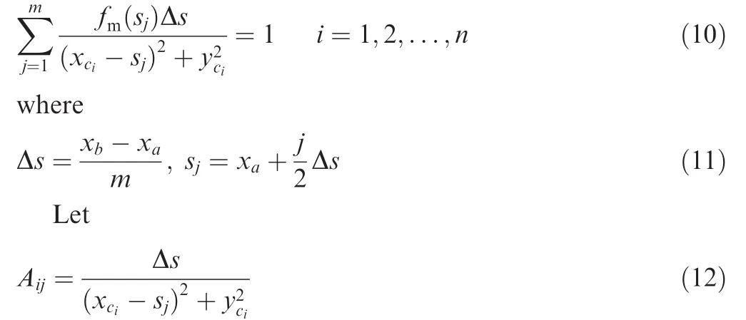
Eq.(10)can be rewritten as

or the matrix form)

where A= (Aij)n×m.Thus,the least square solution can be applied to Eq.(14)to obtaining the function valuesfm(s1),fm(s2),...,fm(sm).As a by-product,a numerical stream function that can be used for the flow field modeling is available,as

The numerical stream function in Eq.(15)is easy to implement in practice,and can provide high precision with m big enough.But it is not applicable for theoretical analysis and high precision generally implies huge computational cost.So,an analytical solution forfm(s)is necessary.
3.1.4.Analytical solution
Oncefm(s1),fm(s2),...,fm(sm)are obtained through Eq.(7),the analytical solution tofm(s)can also be obtained through the polynomial fitting method.For instance,when the precision requirement is not strict,the 1st order polynomial function as

is enough,wherem0andm1can be determined by the polynomialfitting method with theobtained function valuesfm(s1),fm(s2),...,fm(sm).Then,substituting Eq.(16)into Eq.(7),the analytical expression for ψ(x,y)is obtained as

This analytical stream function is more suitable for theoretical analysis and nonlinear controller design.But when the shape of the receiver aircraft is complex,the 1st-order polynomial function as Eq.(16)maybe not enough and a higher-order polynomial function is required.With the increase of order,the obtained analytical stream function as Eq.(17)will become very complicated.So,in the practical application,there is always a trade-off between simplification and accuracy.
Remark 4.Another feasible method to find the solution to
fm(x)in Eq.(9)is the trial and error method.Letfm(x)take a specific function form.Then adjust the parameters offm(x)
over and over until the boundary condition in Eq.(9)is satisfied.Generally,an approximate solution can be obtained with a few attempts.
Remark 5.The line doublet is very suitable for modeling the 3-D flow field around the body of revolution such as the nose,cockpit,and the body of an aircraft.It is not very effective to modeling the flow field for the extruded body such as wings.Since the theory for flow field of the wing is mature and widely used(the lift force calculation,the tanker vortex flow field and the analysis of the propeller,etc.),its modeling method is only briefly introduced later in this paper.
3.1.5.Streamline simulations
Simulations for Fig.5 are carried out to validate the proposed stream function methods.In these simulations,the interval of the line doublet is chosen asxa=0.1,xb=2.5,and the number of points on the boundary curve isn=30.The simulation results are presented in Fig.6,where Fig.6(a)presents the streamlines calculated by the numerical stream function in Eq.(15)withm=9,and Fig.6(b)withm=20.Fig.6(c)presents the streamlines calculated by the simplified analytical stream function in Eq.(7)withm0=0.03 andm1=0.09.
It can be observed that:(1)under the effect of line doublet,the horizontal streamlines are forced to flow around the boundary as expected,which demonstrates the effectiveness of the proposed flow field modeling method;(2)the numerical stream function in Eq.(15)can achieve sufficient smoothness of the streamlines withmbig enough(in this casem≥20);(3)the simplified analytical stream function in Eq.(7)can achieve a similar modeling effect as the numerical function in Eq.(15)but with far less computation.
3.1.6.2-D velocity vector
Once the stream function ψ(x,y)is obtained,the total wind vector can be obtained through partial differential equations,18

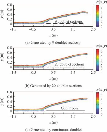
Fig.6 Streamlines produced by line doublets with different distributions.
wherevxandvyare the velocity components.Note thatvxcontains the induced velocity and the free stream velocityV∞,so the induced velocity from the receiver aircraft is obtained as

Along with Eq.(7),it obtains that

Note that:(1)the functionfm(s)is independent ofV∞,which means Eq.(20)can be applied to any refueling speed scenarios by changing the parameterV∞;(2)the functionfm(s)only depends on the shape of the forebody,which means Eq.(20)is applicable to different receiver aircraft by changingfm(s)to the appropriate form.
Remark 6.When the shape of the receiver aircraft is complex,the obtainedfm(s)will be complicated.As a consequence,the analytical integral solution for Eq.(20)may be too complicated.If so,one should do some simplifications forfm(s)or use the numerical form instead of simulations.
3.2.Correction function
The method mentioned above is based on the assumption that the air is inviscid.Since the absence of viscidity and friction will cause error to the actual flow field,an appropriate correction for the obtained velocity vector[up(x,y),un(x,y)]Tis quite necessary.According to the CFD results in Ref.7,the induced velocity decays with the increase of distance to the boundary.Thus,the correction function can be formulated as

wherefu(r)is the correction function,andru(x,y)is a distance function denoting the distance from a point with coordinates(x,y)to the boundary line.
The traditional method to obtain the distance from a point to a curve is very complicated.Because of this,a simple and feasible distance function is developed,shown as

The contours plot forru(x,y)in Eq.(22)is depicted in Fig.7.The results demonstrate that Eq.(22)works well in measuring the distance from a point to the boundary.More importantly,this function makes the full use of the previous calculation result ψ(x,y)from Eq.(7),which is easy to implement in simulations.
Thecorrectionfunctionfu(r)isamonotonicallydecreasingfunctiondependingonmanyfactors,suchastheairviscosity,airdensity,and roughness of the forebody surface.The accurate expression offu(r)maybeverycomplicated.Thus,asimpleapproximatefunction is developed based on the CFD-simulation data,as

wherekuis the attenuation coefficient.According to the CFD-simulation tests,kucan be approximated byku≈1.For higher precision requirements,the exact value ofkushould be determined according to the results from CFD simulations or wind-tunnel tests.

Fig.7 Contours plot for distance function ru(x,y)in range 0 m<ru<0.5 m.
Remark 7.Since¯upand¯unmay have different decay rates,the correction function in Eq.(21)can be further modified as

wherekupandkunare the attenuation coefficients forupandun,respectively.
3.3.3-D velocity vector
As shown in Fig.8,for a body of revolution,the 3-D velocity vector is easy to be obtained according to the symmetry.Given a pointPwith coordinates (x,y,z)in frameRN,the radial plane is defined as the planeOO1Pin Fig.8,where the coordinates (xP,yP)forPare defined as

By substituting (xP,yP)into Eq.(20)and Eq.(21),the 2-D corrected velocity vector[¯up,¯un]Tcan be obtained.After that,the 3-D velocity vector w=[vx,vy,vz]Tis obtained by decomposing¯upand¯unalongx,yandzaxis ofRNas

The above method is applicable to a body of revolution whose cross section is a circle.While for many receiver aircraft like F-16,the cross section of the nose is more like an ellipse.Thus,the scale transformation18should be applied first to transform it into a body of revolution.
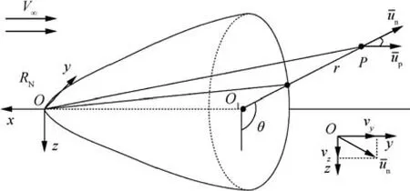
Fig.8 3-D diagram for a body of revolution.
The scale transformation is presented in Fig.9,as

whereaandbare the radii alongzandydirections.Then substituting the transformed coordinates (x′,y′,z′)into Eq.(25)and Eq.(26),a velocity vector w′=[v′x,v′y,v′z]Tis obtained.After that,the scale transformation is applied again to transforming w′back to the original scale,as

Thus,the 3-D velocity vector is obtained as w=[vx,vy,vz]T.
3.4.Flow field superposition
By arranging the line doublet for the nose and the cockpit(see Fig.10)and finishing the procedures mentioned above,the 3-D induced velocity vector for the nose wnoseand the cockpit wcockpitcan be obtained respectively.Then the total velocity vector wforebodyfor the forebody flow field is expressed as

Since the effects of airfoils and probe can be neglected,the bow wave flow field can be approximated as wbow≈wforebody.
Remark 8.If necessary,the airfoil flow field can be modeled according to Ref.13,where the stream function based on circular source and slit sink is used(see Fig.11(a),wheresis the position of the source andhSFis the strength of the source).Note that the procedures to obtain 3-D velocity field of extruded body like wings are slightly different from those of body of revolution.Its procedures are more simple and mature,and readers can refer to Refs.8,13,18.For the effect of the probe,it can be simplified as a slender tube which can be modeled with a point source and sink according to Ref.18as presented in Fig.11(b).Then,the total wind effect from the receiver aircraft can be obtained through Eq.(1).
4.Aerodynamic force on drogue
Since the flow field around the forebody of the receiver is nonuniform,there may exist significant wind gradient around the drogue.A method presented in Ref.8is available to approximate the nonuniform wind with a uniform wind component and a uniform wind gradient component as depicted in Fig.12.

Fig.9 Transformation of an ellipse into a circle.18

Fig.10 Doublet distribution for nose and cockpit.

Fig.11 Flow field modeling for airfoil and slender tube based on stream function defined by source and sink.13,18

Fig.12 Nonuniform wind approximated by a uniform wind and a wind gradient.8


According to Eq.(2),the relative velocity wrelof the surrounding air under the bow wave effect can be expressed as

Let wrel=[vx,vy,vz]T;the drogue airspeedVdr,incidence α and sideslip angle β are defined14as

Then,the aerodynamic force on the drogue can be determined by the aerodynamic coefficients of the drogue.19According to the CFD-simulation results,the aerodynamic coefficients are simplified into the following forms

whereCX,CYandCZare the aerodynamic coefficients that are defined along the body axes of the drogue;CX0,CXα,CXβ,CYβandCZαare drogue coefficients.By combining Eq.(3)and Eq.(33),the total aerodynamic force vector Fdris obtained as

whereSdris the drogue reference area.Meanwhile,by letting wrel=w∞in Eq.(34),the original aerodynamic force can be obtained by

Along with Eq.(4),the induced aerodynamic force ΔFdris finally obtained,as

where ΔFX,ΔFYand ΔFZare the components of ΔFdr.In summary,the key procedures for obtaining ΔFdrare


Table 1 Simulation configuration.
Remark 9.The aerodynamic coefficients in Eq.(33)can be obtained by the wind-tunnel tests or the CFD-simulation tests.The measuring procedures are the same as those widely used in aircraft modeling.15By changing the aerodynamic coefficients,the bow wave effect model can be easily applied to different drogues.
Remark 10.If the accuracy requirement is not strict,in order to reduce the computation,Eq.(30)can be simplified withn=1,as

where pRNdris the position vector of the drogue center.
5.Simulation results and comparison
In this section,the proposed method is applied to an F-16 receiver aircraft.Simulations and comparisons are conducted to validate the obtained bow wave effect model.Section 5.1 describes the refueling simulation configurations,and presents some analytical results from the CFD simulation.In Section 5.2 and Section 5.3,the obtained flow field and aerodynamic force are compared with the results from CFD-simulation,where the observations demonstrate the effectiveness of the proposed modeling method.In Section 5.4,the bow wave effect model is incorporated into an AAR simulation system.The results coincide with the NASA flight-test data.
5.1.Simulation configurations
The simulation parameters used in this paper are illustrated in Table 1,which include the refueling conditions,the physical parameters,and the aerodynamic coefficients.Fig.13 presents the shape and size information of the receiver aircraft and the drogue,which is used in both the proposed model and the CFD simulations.Note that the aerodynamic coefficients of the drogue are obtained through the CFD simulation tests as presented in Ref.15.
In order to validate the effect of the proposed modeling method,a generic receiver aircraft forebody similar to that of F-16 aircraft is used along with a simplified drogue.The CFD analyses are carried out with the widely used commercial software package GAMBIT/FLUENT whose detailed configuration can be found in Ref.12.The 3-D geometric models of the receiver and the drogue are built in GAMBIT as illustrated in Fig.13.After the grids formed,the fluid analysis is performed with FLUENT,where the effects of turbulence are modeled using the k-epsilon standard turbulence model.For CFD simulation,a cuboid region whose far field is kept about 4 times the forebody length is chosen as the computational domain.To achieve adequate precision,the cells near the drogue are high-density with length about 0.01 m,and the total cells are about 2.6 million.A lot of aerodynamic force data of the drogue at different locations around the receiver forebody are obtained by the FLUENT computation,where the force convergence error is within±5 N.
Fig.14(a)shows the path lines around the receiver forebody.Owing to the basket shape of the drogue,the streamlines can flow through the drogue without changing much direction,which indicates that it is reasonable to obtain the aerodynamic force through the flow field.The contours plot of velocity magnitude with FLUENT simulation is illustrated in Fig.14(b).The result shows that the bow wave only changes the flow field in few meters around the forebody,which is in good agreement with NASA report.2Since the bow wave can affect only a limit range,it can be minimized by extending the probe few meters before the nose as applied on the Global Hawk air vehicles.But a long probe may induce other problems like flutter and is easy to damage.Thus,the best way to overcome the bow wave effect is to improve the capacity of the controller,where an effective bow wave model is quite necessary.
Remark 11.To prove that the assumptions made in Assumptions 1 and 2 are rational,a series of CFD simulations is performed with the FLUENT.In these simulations,the angles of attacks of the forebody change from-5°to 45°,and parts of theydirection velocity field results are shown in Fig.15.It can be seen that when αRis very small(-5°to 10°),the flow field around the forebody is not obviously changed(especially in the regions of interest as marked with red dotted box).However,when αRbecomes too big(see Fig.15(c)),the flow field around the forebody is totally changed to turbulent flow and the proposed method based on stream function is no more applicable.So,it should be emphasized that the proposed bow wave modeling method requires that αRand βRshould be small(less than 10°).Under that assumption,letting αR= βR=0°will not reduce the modeling precision much but significantly simplify the bow wave model along with Assumption 2.
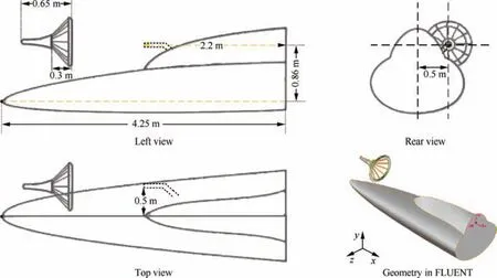
Fig.13 Forebody 3-D geometric parameters used in GAMBIT/FLUENT.

Fig.14 CFD modeling for receiver forebody aerodynamic effect.
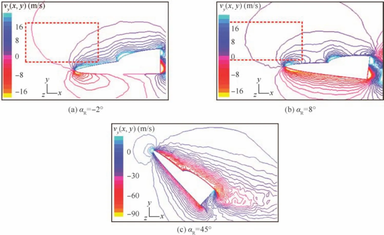
Fig.15 CFD simulation results for different angle of attack.
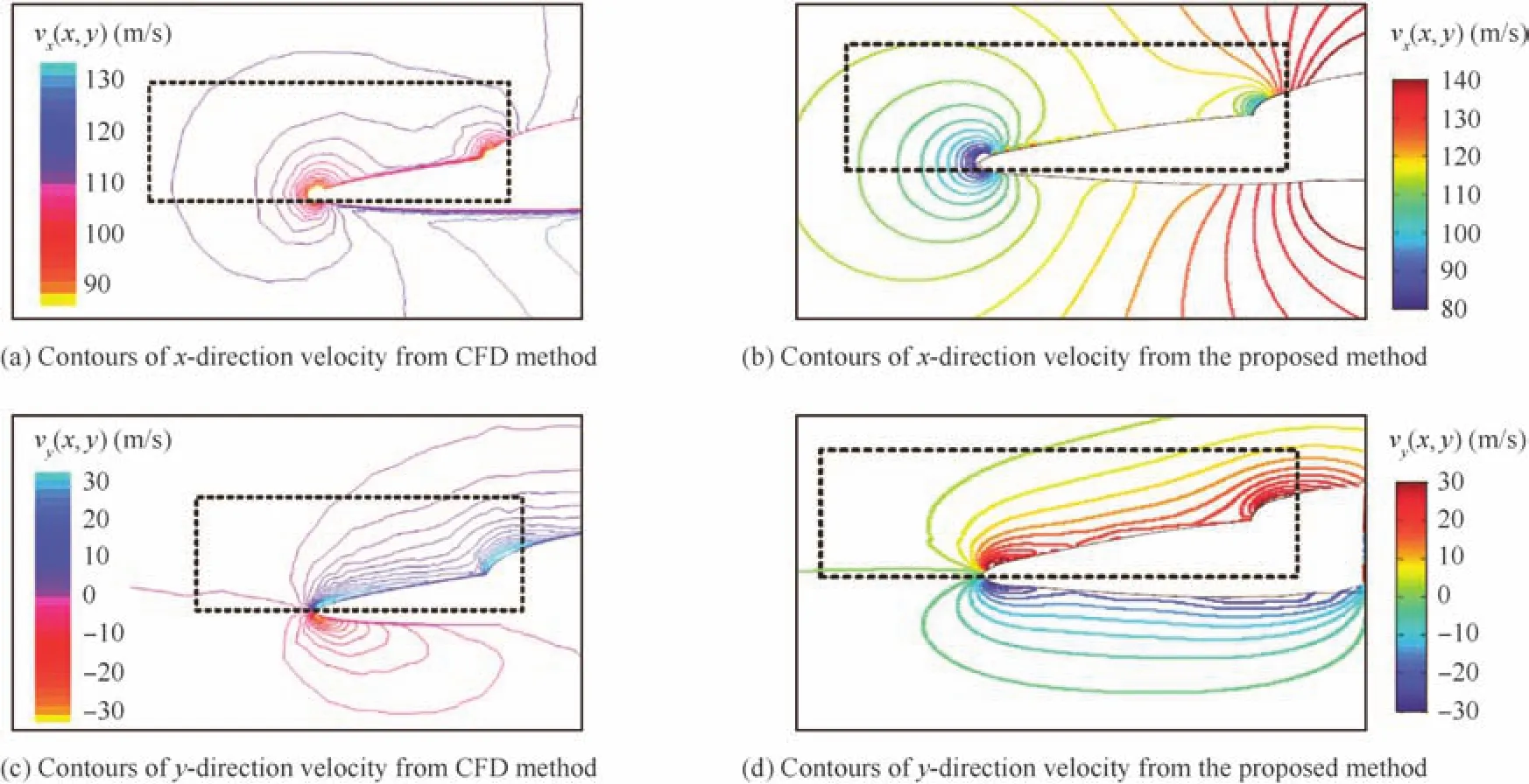
Fig.16 Velocity fields from CFD method and the proposed method.
5.2.Bow wave flow field verification
In this part,the flow field modeling method is used to model the forebody flow field of the F-16 shown in Fig.13.Two simplified stream functions in Eq.(17)are constructed for the nose and the cockpit respectively as Fig.10.A correction function with attenuation coefficientku=1 in Eq.(23)is used.The contour plots of the velocity field around the forebody of the receiver calculated by Eqs.(18–20)are illustrated in Fig.16(b)and(d).As a comparison,the flow field results generated by the FLUENT are presented in Fig.16(a)and(c).
It is observed that,in the modeling regions marked by dotted boxes,the obtained velocity distributions are similar to the CFD results.For the velocity component alongxdirection,it decreases first(before the tip)as blocked by the tip of the nose,then increases along the slope of the forebody surface.As the distance from the surface,the speed magnitude decays to the uniform value.For the velocity component alongydirection,it has the maximum value along the slop of the surface and decays as the distance increases.The velocity distribution rules of the CFD results are consistent well with the paper results.
Noticing that the magnitude distribution(color change)of Fig.16(b)and(d)are slightly different from results in Fig.16(a)and(c).The CFD curves decay faster(about 1.2 times)than the paper results,that is because the attenuation coefficient has not yet been fixed.This error can be eliminated by fine-tuning the attenuation coefficients in Eq.(24),then the modeling precision can be improved.
5.3.Drogue aerodynamic force verification
The 3-D aerodynamic force on the drogue under the bow wave effect is verified in this part.For the forebody in Fig.13,the axial ratio of the nose is εn=1.2 and the axial ratio of cockpit is εc=0.85.The angle of attack of the receiver is αR=6.17°.Other drogue parameters have been presented in Table 1.
In order to test the proposed model,a series of aerodynamic force data is obtained through CFD simulations.The simulation procedures are similar to Ref.12.The CFD calculated force results are placed on the left side of Fig.17 and the results from the proposed method are placed on the right side.In these simulations,a point pRoN(0.5,0.86,0)is chosen as the reference point.Then the drogue is commanded to move from pRoNalongx,yandzdirections ofRNand the results are presented in the vertical three plots.For each plot,the three curves are calculated by the induced aerodynamic force components ΔFX,ΔFYand ΔFZin Eq.(36).
It is observed from Fig.17 that the results from the proposed method coincide well with the CFD results,which proves the effectiveness and accuracy of the bow wave effect modeling method.The paper results are obviously smoother than the CFD results,and their curves are in good agreement with each other.Note that there is a slight difference of the force magnitudes between CFD and the proposed method,such as the maximum force of Fig.17(c)is 50 N and the maximum force of Fig.17(d)is almost 55 N.When using the MATLAB Curve Fitting Toolbox to analyses the matching precision of the CFD data and the paper curves,it can be found that the fitting performance is very high(with fitting degree more than 90%)which indicates that both the magnitude and the tendency fit with the CFD results very well.Also remember that the error as mentioned above can be decreased by trimming the attenuation coefficients in Eq.(24).The MATLAB source code for the bow wave algorithms is published at here:http://dwz.cn/1ZwR6U.
5.4.Aerial refueling simulations
Similar to Ref.11,a MATLAB/SIMULINK based simulation environment has been developed by the authors’lab to simulate the capture stage of AAR procedure.The hose-drogue dynamic model used in this simulation is a 20-links-connected model from Refs.16,20,21.The tanker is a Boeing-707,which is assumed to fly straight and level with constant speed and direction.The receiver is an F-16 nonlinear model modified from the toolbox,22which is a high fidelity model that can simulate the response of an actual F-16 using the high-precision aircraft data.The wind effect from the bow wave effect is modeled by the proposed method.Other wind effects are modeled according to Ref.8,which will be applied to both the receiver and the hose-drogue.The controller of the AAR simulation system is a trajectory tracking controller based on the LQR method modified from Refs.11,14.

Fig.17 Aerodynamic force results from CFD method and the proposed method.
The simulation parameters have been listed in Table 1 and the results during the capture stage are presented in Fig.18.Similar to the NASA report,2the refueling starts when the receiver probe is stable at about 5 m behind the drogue and ends when the longitudinal distance of the probe reaches the capture longitudinal distanceXCAP.If the radial error is within the capture radiusRC,a successful capture is declared,otherwise a miss is declared.2
In this simulation,the capture radiusRC=0.15 m and the capture positionXCAPis at the position 0.2 m before the oil-out valve of the drogue.An approaching speed of 1 m/s is applied by commanding the receiver tracking a point few meters behind the drogue to make sure that the probe has enough velocity to hit the valve open.11After positionXCAPis reached,the receiver is commanded to stop the refueling and fly away rapidly.The drogue and probe position trajectory curves from the proposed simulation system are illustrated in the left of Fig.18 and the corresponding video is available at YouKu:http://dwz.cn/M2JP4 YouTube:https://youtu.be/NR9bIB6rlIY.This video gives a brief introduction to our SIMULINK based AAR simulation system,and shows the movement of the receiver and the drogue in a VR environment.
As a comparison,the NASA AARD flight-test results2are depicted in Fig.18.Note that the receiver used in Ref.2is an F/A-18A aircraft whose bow wave model is not the same as that of F-16.In addition,the refueling conditions are different to some degree.There exist some differences in the two simulation results shown in Fig.18.It should be emphasized that the differences are inevitable,because even between two consecutive experiments the refueling trajectories may be different due to multiple kinds of random disturbances.Even so,the behavior of the drogue under the bow wave effect is very similar.As shown in Fig.18,some common characteristics of the bow wave effect are observed:(1)when the receiver is far away,the drogue is floating around the equilibrium position due to the atmospheric disturbance;(2)the drogue is pushed continuously upward and rightward when the receiver is very close(about 2 m)to the drogue;(3)both captures fail because radial error is out ofRC;(4)the drogue moves away faster than the probe that leads to the failure,which also indicates that the probe bandwidth is too low to adequately track the drogue.All these characteristics are consistent with the bow wave effect in real refueling flight tests,which shows that the proposed method is practical and effective.

Fig.18 Trajectory curves of drogue and probe position from AAR simulations under bow wave effect.
6.Conclusions
This paper analyses the bow wave effect and presents a simple method to model it.Inviscid flow field around the forebody is modeled with the stream function defined by the superposition of basic stream singularities.Then,the aerodynamic coeff icients are used to calculate the induced aerodynamic force on the drogue.Simulations with the obtained bow wave effect model are conducted,and the results are consistent with the CFD-simulation data and flight test data.
The future work will includes:(1)a more practical method to estimate the decay coefficients with the given air conditions developed in future research;(2)AAR controllers based on the proposed bow wave effect model are currently under consideration.
Acknowledgements
This work was supported by the National Natural Science Foundation of China(Nos.61473012 and 51375462).
1.Nalepka JP,Hinchman JL.Automated aerial refueling:extending the effectiveness of unmanned air vehicles.Proceedings of AIAA modeling and simulation technologies conference and exhibit;2005 Aug;San Francisco.Reston:AIAA;2005.p.15–18.
2.Dibley RP,Allen MJ,Nabaa N,Sparks N.Autonomous airborne refueling demonstration phase I flight-test results.2007.Report No.:AIAA-2007-6639.
3.NATO.Air-to-air refuelling.2010.Report No.:ATP-56(B).
4.Quan Q,Wei ZB,Gao J,Zhang RF,Cai KY.A survey on modeling and control problems for probe and drogue autonomous aerial refueling at docking stage.Acta Aeronaut Astronaut Sinica2014;35(9):2390–410 Chinese.
5.Thomas PR,Bhandari U,Bullock S,Richardson TS,Bois JLD.Advances in air to air refuelling.ProgressAerospSci2014;71:14–35.
6.Lu YP,Yang CX,Liu YY.A survey of modeling and control technologies for aerial refueling system.Acta Aeronaut Astronaut Sinica2014;35(9):2375–89 Chinese.
7.Dogan A,Blake W,Haag C.Bow wave effect in aerial refueling:Computationalanalysisand modeling.JAircraft2013;50(6):1856–68.
8.Dogan A,Lewis TA,Blake W.Flight data analysis and simulation of wind effects during aerial refueling.J Aircraft2008;45(6):2036–48.
9.Hansen JL,Murray JE,Campos NV.The NASA dryden AAR project:A flight test approach to an aerial refueling system.2004.Report No.:AIAA-2004-4939.
10.Ro K,Kuk T,Kamman JW.Active control of aerial refueling hose-drogue systems.2010.Report No.:AIAA-2010-8400.
11.Bhandari U,Thomas PR,Bullock S.Bow wave effect in probe and drogue aerial refuelling.2013.Report No.:AIAA-2013-4695.
12.Khan O,Masud J.Trajectory analysis of basket engagement during aerial refueling.2014.Report No.:AIAA-2014-0190.
13.Dogan A,Blake W.Modeling of bow wave effect in aerial refueling.2010.Report No.:AIAA-2010-7926.
14.Stevens BL,Lewis FL.Aircraft control and simulation.2nd ed.New York:Wiley;2003.p.73–4.
15.Ro K,Basaran E,Kamman JW.Aerodynamic characteristics of paradrogue assembly in an aerial refueling system.J Aircraft2007;44(3):963–70.
16.Ro K,Kamman JW.Modeling and simulation of hose-paradrogue aerial refueling systems.J Guid Control Dyn2010;33(1):53–63.
17.Waishek J,Dogan A,Blake W.Derivation of the dynamics equations of receiver aircraft in aerial refueling.J Guid Control Dyn2009;32(2):586–98.
18.RauscherM.Introductiontoaeronauticaldynamics.New York:Wiley;1953.p.188–264.
19.Williamson WR,Reed E,Glenn GJ,Stecko SM,Musgrave J,Takacs JM.Controllable drogue for automated aerial refueling.J Aircraft2010;47(2):515–27.
20.Ribbens WB,Saggio F,Wierenga R,Feldmann M.Dynamic modeling of an aerial refueling hose&drogue system.2007.Report No.:AIAA-2007-3802.
21.Wang HT,Dong XM,Xue JP,Liu JL.Dynamic modeling of a hose-drogue aerial refueling system and integral sliding mode backstepping control for the hose whipping phenomenon.Chin J Aeronaut2014;27(4):930–46.
22.Russell RS.Non-linear F-16 simulation using Simulink and Matlab.2003.
29 May 2015;revised 12 August 2015;accepted 27 November 2015
Available online 24 February 2016
ⓒ2016 Chinese Society of Aeronautics and Astronautics.Published by Elsevier Ltd.This is an open access article under the CC BY-NC-ND license(http://creativecommons.org/licenses/by-nc-nd/4.0/).
*Corresponding author.Tel.:+86 10 82338464.
E-mail addresses:dai@buaa.edu.cn(X.Dai),whisper@buaa.edu.cn(Z.Wei),qq_buaa@buaa.edu.cn(Q.Quan).
Peer review under responsibility of Editorial Committee of CJA.
Dai Xunhuareceived the B.S.degree in School of Automation Science and Electrical Engineering at Beihang University in 2013,and is currently pursuing a M.S.degree at here.His main research interests are aerial refueling and flying control.
Wei Zibois a Ph.D.student at School of Automation Science and Electrical Engineering at Beihang University.His main research interests are aerial refueling,accurate flight control and iterative learning control.
Quan Quanreceived the B.S.and Ph.D.degrees from Beihang University in 2004 and 2010,respectively.He has been an associate professor in Beihang University since 2013.His main research interests include vision-based navigation and reliable flight control.
 CHINESE JOURNAL OF AERONAUTICS2016年2期
- CHINESE JOURNAL OF AERONAUTICS的其它文章
- Hypersonic starting flow at high angle of attack
- Advances and trends in plastic forming technologies for welded tubes
- Instability and sensitivity analysis of flows using OpenFOAM®
- Numerical simulations of high enthalpy flows around entry bodies
- Modeling and simulation of a time-varying inertia aircraft in aerial refueling
- Experimental investigations for parametric effects of dual synthetic jets on delaying stall of a thick airfoil
