Hypersonic starting flow at high angle of attack
Bai Chenyuan,Wu Ziniu
Department of Engineering Mechanics,Tsinghua University,Beijing 100084,China
Hypersonic starting flow at high angle of attack
Bai Chenyuan,Wu Ziniu*
Department of Engineering Mechanics,Tsinghua University,Beijing 100084,China
Hypersonic;Normal force;Shock waves;Starting flow;Unsteady flow
Compressible starting flow at small angle of attack(AoA)involves small amplitude waves and time-dependent lift coefficient and has been extensively studied before.In this paper we consider hypersonic starting flow of a two-dimensional flat wing or airfoil at large angle of attack involving strong shock waves.The flow field in some typical regions near the wing is solved analytically.Simple expressions of time-dependent lift evolutions at the initial and final stages are given.Numerical simulations by compuational fluid dynamics are used to verify and complement the theoretical results.It is shown that below the wing there is a straight oblique shock(OSW)wave,a curved shock wave(CSW)and an unsteady horizontal shock wave(USW),and the latter moves perpendicularlly to the wing.The length of these three parts of waves changes with time.The pressure above OSW is larger than that above USW,while across CSW there is a significant drop of the pressure,making the force nearly constant during the initial period of time.When,however,the Mach number is very large,the force coefficient tends to a time-independent constant,proportional to the square of the sine of the angle of attack.
1.Introduction
In a number of flight problems the wing may involve sudden unsteady motion,including sudden acceleration,vertical step motion,or change of angle of attack.The problem to determine the flow and the force for such problems are known as starting flow problem,firstly studied by Wagner1and Walker2for the case of incompressible flow at small angle of attack(AoA).For supersonic starting flow of a two-dimensional wing at small angle of attack,a linear theory is built by Heaslet and Lomax,3who showed that the flow on both sides of the wing is divided into three regions separated by two characteristic lines.The lift was shown to be constant for a short period of time and then increases monotonically to its steady state value following an arcsine type curve.Lomax et al.4then extended the linear theory to consider the indicial lift of two and three dimensional wings at both subsonic and supersonic flow speeds.Lengthy expressions are provided for the calculation of the indicial functions which give the time-dependent variation of the lift.For aeroelasticity application,piston theory was developed5–8which can be used to calculate the pressure load due to local motion of the body.For convenience of applications,the lift and moment of the wings are expressed as indicial functions for arbitrary motions of the wings.9–13Now the indicial lift refers to a time-dependent aerodynamic response to a step change in airfoil motion.For sufficientlysmall motions,the indicial lift function is a linear perturbation of the airfoil downwash distribution from an established steady state.13
Starting flow at large angle of attack has been extensively studied for incompressible flow.Graham14found that the initial lift is singular(infinite)when the angle of attack is large,due to the rolling up of trailing edge vortex,in contrary to small AoA starting flow for which the initial lift is one half of its steady state value and increases monotonically with time following a curve known as Wagner function.1Recently,the long time behavior of lift variation for large angle of attack starting flow has been studied by using experimental measurement,15by discrete vortex simulation,16or by theory.17According to these studies for high angle of attack incompressible starting flow,the lift undergoes a three-phase variation possible repeatable in time17:(a)initial lift drops due to Graham singularity,(b)a Wagner type lift increase enhanced by leading edge vortex close to the leading edge,and(c)a lift drop due to a lift-decreasing trailing edge vortex spiral induced by the leading edge vortex convected to the trailing edge.
In spite of the above numerous studies,starting flow at high angle of attack for compressible flow has received few attentions.Bai,Li and Wu18performed numerical computation of starting flow at subsonic,transonic and supersonic speeds at high angle of attack.They showed that for subsonic starting flow at large angle of attack,the initial lift is given by the piston theory,which means the Graham singularity of the initial lift is removed by compressibility.Though trailing edge vortex spirals are still observed,the lift coef ficient is a decreasing function of the Mach number for suf ficiently large time.This is in contrast with our common knowledge that compressibility increases lift for subsonic flow.No details are given for the properties of supersonic and hypersonic starting flow.
In this paper,we study hypersonic starting flow of a twodimensional wing without thickness but at large angle of attack.We will derive some useful expressions for the pressure coefficients along the wing and the initial and final value of the normal force coefficient.Section 2 is devoted to flow structure and pressure expressions.Section 3 is concerned with the normal force coefficient.Both theory and computational fluid dynamics simulation(for the Euler equations)are used for analysis.
2.Flow structure and pressure coefficient
A two-dimensional wing(of chord lengthcA)at rest is impulsively set into motion at a constant speedV∞with an angle α between the direction of motion and the chordline of the wing.As usual,we use a body fixed frame with the horizontal axisxalong the chordline of the wing andyperpendicular to it.Once started,the flow has an initial uniform velocityV∞at angle of attack α.Mach waves in the linear case and shock and expansion waves in the nonlinear case are then generated from the surface of the wing and propagate outward,leading to a time-dependent variation of the pressure on the wing.Thus,the forceF,normal to the wing for inviscid hypersonic flow,is also time dependent.The density,pressure,sound speed,Mach number,velocity and velocity components are denoted as ρ,p,a,Ma,Vandu,v,respectively.The pressure coef ficient and normal force coef ficient are defined asCp=(p-p∞)/q∞andCn=F/(q∞cA).Hereq=1ρV2.The speci fic heat is
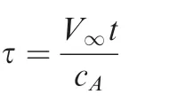
This non-dimensional time measures the number of chords traveled at the given timet.We first need to recall the linear solution by Heaslet and Lomax.3
2.1.Recall of the linear theory
Supersonic starting flow at small angle of attack has been studied long ago by Heaslet and Lomax.3The solution on the surface of the wing is divided into three zones labeled I,II and III.The three regions are schematically displayed in Fig.1.The boundary between regions I and II isxl=(u∞-a∞)tand the boundary between regions II and III isxr=(u∞+a∞)t.We emphasize that it is the horizontal componentu∞of the velocity that determines these boundaries.In the linear case of Heaslet and Lomax,3this component may be regarded as nearly equal toV∞,so thatMa∞=V∞/a∞≈u∞/a∞,but for the present nonlinear case with large angle of attack(considered below),u∞differs much fromV∞.
Zone I spreads over 0<x<xland has the steady-state Ackreret-type solution with the pressure coefficient given by

where ‘‘+” denotes the lower surface of the wing and ‘‘-”denotes its upper surface.

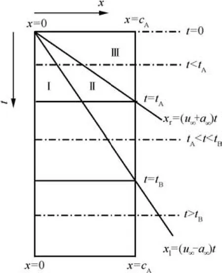
Fig.1 The flow just below the wing is divided into regions I,II and III.
Zone III spreads overxr<x<cAand has simple wave solution which was extended as Piston theory by Ashley and Zartarian6to treat aeroelasticity.
Zone II spreads overxl<x<xrand has a conical flow solution with the pressure coefficient given by

2.2.Study of nonlinear waves at large angle of attack
At large angle of attack,the flow below the wing is under strong compression so that we have shock waves now.The flow above the wing is under expansion so that we have expansion waves.The solution in general supersonic flow will be considered elsewhere,here we consider the hypersonic limit so that simpli fied solutions can be obtained directly.First consider compression waves below the plate.Before doing analysis we show some evidence of the flow structure by computational fluid dynamic(CFD)simulation.
In Fig.2 we display the Mach contours obtained by CFD computation at three typical instants forMa∞=6 and α =20°.The CFD method used is the same as that in reference.18A second order Roe scheme with finite difference formulation and with 200 grids points along each side of the plate.A time step of Δτ=10-3is used in the numerical simulation.This choice of numerical method has been demonstrated to be accurate enough for starting flow simulation.17,18From Fig.2,we observe a steady and straight oblique shock wave(OSW)and an unsteady horizontal shock(USW)moving downward.These two shock waves are connected by a curved shock wave(CSW)and the extensions of these three parts vary with time.The unsteady horizontal shock wave moves downward at a constant speed φN,leaving a uniform state between this shock wave and the wing.
CFD simulations with other choice of conditions lead to similar conclusions.Thus,as in linear case,the flow below the wing can also be divided into three regions.Region I(labeled 1)is between the straight part of the oblique shock wave and the wing.Region III(labeled 3)is between the moving horizontal shock wave and the wing.Region II(labeled 2)is between region I and region III.The boundaries between each two neighboring regions will be discussed below.
(1)Steady oblique shock wave solution.The length of the steady state oblique shock wave from the leading edge varies with time,and we have a uniform state(denoted region 1)between the straight part of this shock wave and the wing.The pressurep1and pressure coefficientin region ICp1= (p1-p∞)/q∞are given by the following well-known shock relation

The shock angle β is related to α andMa∞by the classical shock angle relation


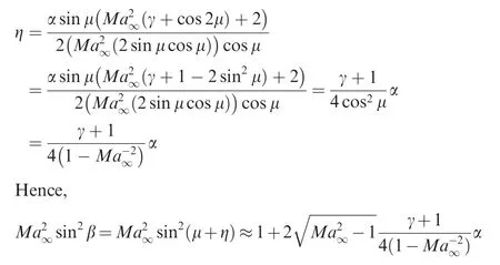
and therefore the use of Eq.(5)gives

The Mach number and density in region 1 are


Fig.2 Mach contours at three typical instants.
For hypersonic flow with very large Mach number,it is well-known and also easily checkable that the shock angle relation(6)can be simplified as

Put this into Eq.(5)we get

(2)Unsteady horizontal shock wave solution.We also have a uniform state(denoted region 3)between this shock wave and the wing.The horizontal velocity does not change across the shock wave so thatu3=V∞cos α,while the vertical velocity and pressure are related through the classical moving shock relation

This vertical velocity jumps fromv∞=V∞sin α below the shock tov3=0 in order to satisfy the non-penetrating condition across the wing,thus


For the pressure coefficient

For small α we recover from Eq.(9)the linear solution given by Eq.(2).
The speed of this shock wave φNis related to the pressure ratio by the well-known expression

Put this into Eq.(10)and we get


Fig.3 displays the pressure ratioCp3/Cp1as functions of Mach number for various angles of attack.It is seen that for larger angle of attack the ratioCp3/Cp1is smaller,meaning that the steady shock generates a compression stronger than the unsteady horizontal shock wave.WhenMa∞→∞,we have howeverCp3→Cp1for all α.
In summary,the flow below the wing is composed of three regions similarly as in the linear case:
Region I is between the straight part of the oblique shock wave and the wing,with pressure coefficient defined by Eq.(5)or Eq.(7)for hypersonic flow.
Region III is between the moving horizontal shock wave and the wing,with the pressure coefficient defined by Eq.(9).
Region II is between region I and region III.The boundary between regions I and II isxl=(u∞-a∞)tin the linear case,and should roughly bexl=(u1-a1)tin the nonlinear case.The boundary between regions II and III isxr=(u∞+a∞)tin the linear case,and should roughly bexr=(u1+a1)tin the nonlinear case.In the hypersonic limit the sound speed is small in comparison with the convective speed,region II defined byxl<x<xris narrow.For nonlinear case it appears to be difficult to obtain analytical solution in region II and this lack of knowledge is left in this paper to be obtained by numerical solution by CFD.
In Figs.4 and 5,we display pressure coefficients in the two dimensional space and distribution along the plate at three typicalinstants τ=0.5,1.2and2forMa∞=6and α =20°.The solution displayed in Fig.4 is obtained by numerical simulation.In Fig.5(b)we also display theoretical solution.It is seen that the pressure coefficient above the wingCp,upp≈-0.039.In fact,for angle of attack large enough,the expansion wave leads to a pressurepuppon the upper surface much smaller thanp∞.Thus

ForMa∞=6,the use of Eq.(11)givesCp,upp≈ -0.0397,which is very close to the CFD resultCp,upp≈-0.039,see Fig.5(a)for the pressure coefficient along the upper surface.Hence,the pressure coefficient along the upper surface of the plate can be estimated by Eq.(11)at least forMa∞≥6.
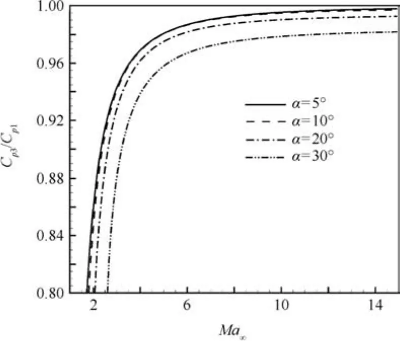
Fig.3 Pressure ratio Cp3/Cp1as a function of Ma∞ for α =5°,10°,20°,30°.
The pressure coefficient along the lower surface of the wing is shown in Fig.5(b).The Eq.(5)givesCp1=0.3272 and Eq.(9)givesCp1=0.3212.These two values are marked as dashed lines in Fig.5(b)and compare well with CFD solution.It is interesting to note that CFD solution gives a lower pressure solution in Region II,as is clear in Fig.5(b)(point M).This type of expansion with a local reduction of pressure has been predicted by Heaslet and Lomax3in the linear case.The observation of this phenomenon in high angle of attack starting flow may suggest that this is a general phenomenon,deserving further studies in the future.This depression may explain the constancy of the force during the initial period of time,as in the linear case(see the next section).

Fig.4 Contours of pressure coefficients at three typical instants.
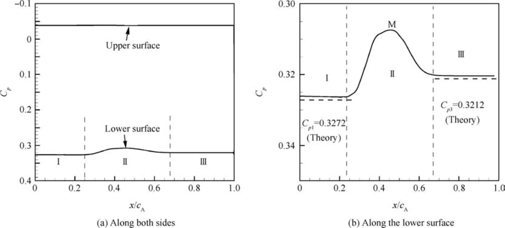
Fig.5 Pressure coefficients along the flat plate for Ma∞ =6 and α=200°at τ=0.5.
3.Lift or normal force evolution at large AoA

3.1.Recall of lift coefficient for linear case

(1)For τ< τA,the wing is subjected to pressure influence by all the three regions,and the normal force coefficient is a constant given by

(2)For τA< τ< τB,the wing is subjected to pressure influence by regions I and II,and the normal force coefficient is
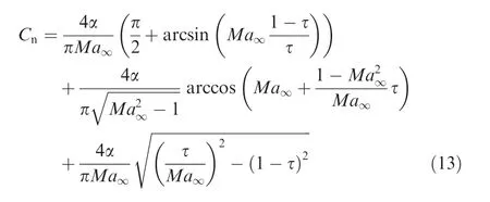
(3)For τ> τBthe wing is subjected to pressure influence only by region I,and the normal force coefficient is constant given by

3.2.Normal force coefficient for large angle of attack

The initial lift is due to region III with pressurep3.Thus the initial normal force coefficient isCn=Cp3-Cp,upp.Due to the some mechanism as in linear case and due to the depression in region II(see pointMin Fig.5(b)),for τ< τAthe normal force coefficient is expected to be nearly constant and is given byCn=Cp3-Cp,upp.Using Eq.(9)forCp3and Eq.(11)forCp,upp,we have


For τ> τB,the wing is subjected to the influence of region I only,so that the normal force coefficient isCn=Cp1-Cp,upp.Using Eq.(5)forCp1we get


For hypersonic flow with very largeMa∞,we may use(7)forCp1so that the normal force coefficient takes the following explicit form
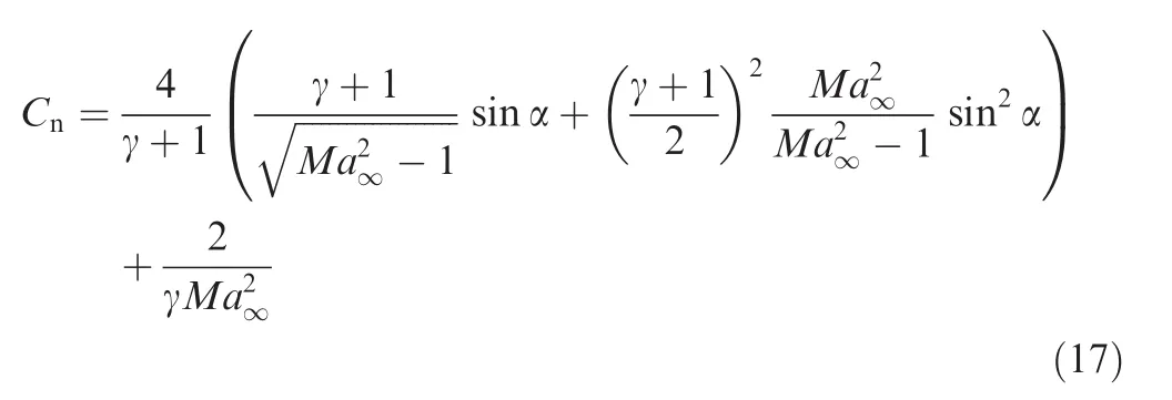

3.3.Pressure and normal force coefficient at very large Mach number
Now consider the hypersonic case at very large angle of attack,with the following constraint

Under the assumption(18),the use of Eqs.(7)and(9)gives

Hence,in the hypersonic limit(18),the pressure coefficientsCp1andCp3have the same expressions.
By Eq.(15)and by Eq.(17),the force coefficientCnfor all time in the hypersonic limit is

3.4.Comparison of results obtained by theory and CFD
Fig.6 displays the time evolution of the normal force coeff icient forMa∞=6,8,10 and 12 at α =20°.Solid lines are CFD results,while dashed lines,indicating the initial and final force coefficients,are given by Eqs.(15)and(16),respectively.Thus,expressions(15)and(16)predict well the initial and final force coefficients.
Two important conclusions are obtained.WhenMa∞→∞,the force coefficientCnis a straight horizontal line,predicted by Eq.(20).For very largeMa∞,aerodynamic heat and real gas effect may be important19and this problem deserves further studies.


and the convection of the boundariesxlandxrto the right should make the lift coefficient increase in time even at the initial period of time.However,the depression in zone II(see the pressure coefficient close to the point M in Fig.5(b)),with a pressure coefficient given by Eq.(3),exactly compensate the increase byCp1-Cp3so that the lift coefficient is constant and given by Eq.(12)for 0<τ<τA.According to the present study,we also have a nearly constant force coefficient at an initial period of time even for large angle of attack starting flow,where Mach waves are replaced by nonlinear shock waves.The nature of the depression in zone II as shown in Fig.5(b)needs further studies.
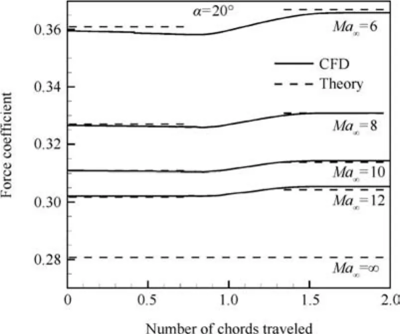
Fig.6 Normal force coefficients versus time for various Mach numbers at α =20°.
The force coefficient is not 0 at the initial time,similarly as in starting flow of other flow regions.For incompressible flow at small angle of attack,the initial lift is due to the variation of circulation.1–4For incompressible large angle of attack flow,the initial lift is even singular,14due to the close interaction of a trailing vortex spiral with the wall.For compressible starting flow at small angle of attack,the initial lift is due to the piston effect,i.e.,compressible acoustic wave in the windward flow side and expansion acoustic wave in the leedward flow side.3,4,6,7For the present hypersonic flow case with large angle of attack,the initial lift is due to the impulsively generation of a horizontal shock wave below the wing and partly due to expansion above the wing,which can also be classi fied into nonlinear piston effect.
Note that,in Fig.6,the force coef ficient obtained by CFD is smaller than that of theory atMa∞=6,while the contrary result is found atMa∞=12.This can be explained.If there were no other systematic errors,CFD should have some numerical errors due to the inefficiency of grid resolution.This would be the reason why we observe a difference of results atMa∞=12.The theory used the approximation(11)for the pressure coefficient in the leeward flow side,which for small Mach number underestimates the pressure in this side and overestimates the force coefficient.This may explain why the force coefficient obtained by CFD is smaller than that of theory atMa∞=6.However,the differences of force coefficients by theory and CFD are small here.
4.Conclusions
In this paper,we have studied hypersonic starting flow at large angle of attack.Both CFD computation and shock wave theories are used to study the pressure and normal force evolution.We have derived the initial and final force coefficient expressions,see Eqs.(15)and(16).There is a shock wave below the wing,composed of a steady oblique shock wave and an unsteady horizontal shock wave,connected by a curved shock wave.The normal force coefficient is initially nearly constant,then increases monotonically in time before the steady state value is reached.In the case of very large Mach number,it is shown that the normal force coefficient is independent of both Mach number and time.
The depression observed between the flow regions across the steady oblique shock wave and across the horizontal shock wave appears to be the reason of the constancy of the force at the initial period.For very large Mach number,the solution here has been obtained using perfect gas assumption.This depression and the possible real gas effect should be considered in future studies.In addition,starting flow at high angle of attack under subsonic and supersonic conditions also needs studies.20Another issue is possibly the viscosity effect.Presently we have only considered inviscid flow,which may be a good approximation of real viscous flow if the boundary layer remains attached.However,for large angle of attack,the boundary layer in the leeward flow side would separate to shed vortices at least for subsonic flow.For the present hypersonic flow case,the inclusion of viscosity effect may deserve a further study if flow details should be considered.However,the conclusions reported here may still be significant,since the pressure on the leeward flow side can be considered as vanished in the hypersonic limit,i.e.,the pressure coefficient can be approximated by Eq.(11)which also holds approximately in the viscous flow case.The last issue that requires further studies is supersonic starting flow at high angle of attack,for which the nonlinear wave interaction is more complex.21
Acknowledgements
This work was supported by the Natural National Science Foundation of China(No.11472157).The authors are grateful to Referees for their valuable comments leading to an improvement of this paper.
1.Wagner H.Uber die enstehung des dynamischen auftreibes von tragflugeln.Z.Angew.Math.Mech.1925;5:17–35.
2.Walker PB.Growth of circulation about a wing and an apparatus for measuring fluid motion.London:Aeronautical Research Communication;1931,Report No.:1402.
3.Heaslet MA,Lomax H.Two-dimensional unsteady lift probIems in supersonic fIight.Washington,D.C.:NACA;1949,Report No.:NACA-TN-1621.
4.Lomax H,Heaslet MA,Fuller FB,Sluder L.Two-and threedimensional unsteady lift problems in high-speed flight.Washington,D.C.:NACA;1952,Report No.:NACA-TR-1077.
5.Lighthill MJ.Oscillating airfoils at high Mach number.J.Aeronaut.Sci.1953;20(6):402–6.
6.Ashley H,Zartarian G.Piston theory–A new aerodynamic tool for the aeroelastician.J.Aeronaut.Sci.1956;23(12):1109–18.
7.Liu DD.From piston theory to a unified hypersonic–supersonic lifting surface method.J.Aircr.1997;34(3):304–14.
8.Dowell EH,Bliss DB.New look at unsteady supersonic potential flow aerodynamics and piston theory.AIAAJ.2013;51(9):2278–81.
9.Leishman JG.Validation of approximate indicial aerodynamic functions for two-dimensional subsonic flow.J.Aircr.1988;25(10):914–22.
10.Leishman JG.Unsteady lift of a flapped airfoil by indicial concepts.J.Aircr.1994;31(2):288–97.
11.Nagarajan H,Leishman JG.Unsteady aerodynamics of a flapped airfoil in subsonic flow by indicial concepts.J.Aircr.1996;33(5):855–68.
12.Sitaraman J,Baeder JD.Computational-fluid-dynamics-based enhanced indicialaerodynamic models.J.Aircr.2004;41(4):798–811.
13.Jaworski JW,Dowell EH.Supersonic indicial lift functions from transform methods.AIAA J.2007;45(8):2106–11.
14.Graham JMR.The initial lift on an aerofoil in starting flow.J.Fluid Mech.1983;133:413–25.
15.Pitt Ford CW,Babinsky H.Lift and the leading-edge vortex.J.Fluid Mech.2013;720:280–313.
16.Xia X,Mohseni K.Lift evaluation of a two-dimensional pitching wing.Phys.Fluids2013;25(9):1838–43.
17.Li J,Wu ZN.Unsteady lift for the Wagner problem in the presence of additional leading/trailing edge vortices.J.Fluid Mech.2015;769:182–217.
18.Bai CY,Li J,Wu ZNProceedings of ASME International Mechanical Engineering Congress;2015 Nov 13–19.Houston,New York:ASME;2015.
19.Anderson JD.Hypersonic and high temperature gas dynamics.2nd ed.Reston:AIAA;2006.
20.Wu ZN,Bai CY,Xu SS,Li J,Lin J,Chen ZJ,Yao Y.Impulsively starting flow problem:from incompressible to hypersonic flow.Acta Aeronaut.Astronaut.Sinica2015;36(8):2578–90.
21.Bai CY,Wu ZN,2015.Supersonic indicial response with nonlinearcorrectionsby shock and rarefaction waves,in preparation.
6 November 2015;revised 17 February 2016;accepted 17 February 2016
Available online 23 February 2016
ⓒ2016 Chinese Society of Aeronautics and Astronautics.Published by Elsevier Ltd.This is an open access article under the CC BY-NC-ND license(http://creativecommons.org/licenses/by-nc-nd/4.0/).
*Corresponding author.
E-mail addresses:bcy12@mails.tsinghua.edu.cn(C.Bai),ziniuwu@tsinghua.edu.cn(Z.Wu).
Peer review under responsibility of Editorial Committee of CJA.
Bai Chenyuanis a Ph.D.student at Department of Engineering Mechanics,Tsinghua University.She received her B.S.degree from Tsinghua University in 2012.Her area of research is aerodynamics.
Wu Ziniureceived the B.S.degree in aerodynamics from Beijing Institute of Aeronautics and Astronautics in 1985 and the Ph.D.degree in Mechanics from University of Paris Six in 1992.He worked as a researcher engineer in ENSAM Paris.After 1994,he first joined BUAA as an associate professor and full professor,and then Tsinghua University as a full professor.His main research interests are aerodynamics,shock waves and vortex flows.
 CHINESE JOURNAL OF AERONAUTICS2016年2期
- CHINESE JOURNAL OF AERONAUTICS的其它文章
- Advances and trends in plastic forming technologies for welded tubes
- Instability and sensitivity analysis of flows using OpenFOAM®
- Numerical simulations of high enthalpy flows around entry bodies
- Modeling and simulation of a time-varying inertia aircraft in aerial refueling
- Experimental investigations for parametric effects of dual synthetic jets on delaying stall of a thick airfoil
- Experiments on unsteady vortex flowfield of typical rotor airfoils under dynamic stall conditions
