Formation of interlayer gap and control of interlayer burr in dry drilling of stacked aluminum alloy plates
Tian Wei,Hu Jian,Liao Wenhe,Bu Yin,Zhang Lin
College of Mechanical and Electronical Engineering,Nanjing University of Aeronautics and Astronautics,Nanjing 210016,China
1.Introduction
Under the premise of meeting the strength requirements of aircraft structure,lightweight is the goal to pursuit in aircraft manufacturing.Hence,aluminum alloy,titanium alloy and composite materials are widely used in aviation manufacturing industry.1–3In aircraft component assembly,connection andhole quality of connection with multi materials’stacks are key factors affecting fatigue and service life of aircraft,and many researches have been carried to improve the drilling quality.4–8Hence,automatic drilling system based on industry robot or crawler robot has wide application in modern aircraft manufacturing industry.9–11And during traditional drilling process for stacked metal materials,interlayer burr with large size occurs,which needs a lot of time and money for hand deburring.12In addition,interlayer burr removing needs to separate the parts and reassembly after deburring,and it not only increases the manufacturing cost but also is dif ficult to ensure the assembly quality.
Manystudieshavebeen conducted related to burr formation and minimization in drilling metal materials.13–18A lot of researches indicate that workpiece parameters,tool parameters and process parameters have remarkable impact on burr size;in addition,tool wear and temperature field distribution have a certain effect on burr size.Melkote et al.discussed the in fluence of tool geometry,coating material,process parameters and tool wear on interlayer burr formation in dry drilling 2024-T3 and 7075-T6 stacked plates15They found tool point angle,workpiece clamping type and clamping distance are the signi ficant factors in fluencing interlayer burr height,while tool wear barely has an effect on interlayer burr height.Bi et al.proposed a multi-objective optimization algorithm for process parameter optimization during drilling Ti6Al4V and 7075-T6 stacked plates,and found the spindle speed of 2000 r/min,the feed rate of 0.075 mm/r,the pressure of 0.3 MPa and Ti–Al stacking sequence can achieve the smallest interlayer burr height.16Finite element method is used to investigate the mechanism of burr formation.19–21Min et al.studied finite element simulation on the formation of uniform burr and crown burr when drilling different plastic materials;the finite element model can evaluate the in fluence of process parameters on burr formation,and the simulation results were validated by experiments.20Segonds et al.analyzed the ductile material deformation mechanism under the effect of twist drill,and propose a new model to predict the drilling exit burr type.22Kim and Dornfeld discussed drilling exit burr formation mechanism with several shapes and size in drilling various materials and built a mathematical model of drilling exit burr based on energy conservation,and the theoretical model is in good agreement with the experimental results;it is only applicable for good plastic material with low spindle speed and the in fluence of spindle speed was not taken into account.23
Interlayer gap is an important factor in fluencing interlayer burr height,and the relationship between interlayer gap and interlayer burr height are widely discussed.24–26When drilling stacked layers with different metal materials,the elastic bending deformation of two layers occurs to different degrees because of various physical and mechanical properties,and then the interlayer gap and interlayer burr form.Even for the same material drilling process,the upper plate produces elastic recovery when it is drilled through,and the lower plate without object support produces large elastic bending deformation,and forms big interlayer gap,which provides favorable conditions for interlayer burr formation.Choi et al.proposed a finite element model of interlayer gap formation when drilling stacked metal materials and pointed out that the interlayer gap increases dramatically while the plastic deformation region of upper layer reaches to the exit of hole and the lower layer is supported by the drill,then the interlayer burr develops fully.24Li et al.carried out a mathematical model of interlayer gap during the drilling of stacked material and discussed the effect of preloaded pressing force on interlayer gap;the model is made too much simpli fication and is invalid when the pressing force is larger than drilling force,and there is no experiment to validate the model.25Liang simpli fied the deformation of thin plates into the deformation of beams,develops an analytical model of interlayer gap formation,and discusses the relationship between the interlayer gap and the interlayer burr morphology.26
Although some researches about interlayer gap in drilling stacked metal materials have been reported,the effect of interlayer gap on interlayer burr height and the inhibit mechanism of pressing force on interlayer burr height is not clear.This paperaimstohaveaprofoundunderstandingofthe mechanism of interlayer gap formation and control of interlayer burr under preloaded pressing force in drilling stacked metal materials.Section 2 discusses the formation of interlayer burr and the interlayer gap.In Section 3,a simpli fied mathematical model for interlayer gap without pressing force and an FEM( finite element method)model for interlayer gap with pressing force are given.Section 4 shows the experimental works.In Section 5,the results and discussion are presented.Finally,several conclusions are drawn in Section 6.
2.Formation of interlayer burr and interlayer gap
2.1.Interlayer burr formation
The formation of drilling exit burr is complicated due to many in fluencing factors.27–29Two typical burr formation mechanisms are presented in Fig.1.The metal material is cut gradually in feed direction under the effect of twist drill,when the drill is near the exit of hole,the center point of uncut material on exit surface is firstly yielded,apparently,the minimum thickness of uncut material,h0(see Fig.1(b)),indicates the distance from center point of exit surface to chisel edge,is affected by material properties and thrust force.Yielded zone constantly extends outward and at the same time,the yielded material under thrust force produces plastic deformation.And then,the deformation of exit material can be divided into two cases,namely,Case 1 and Case 2.In Case 1,the material under chisel edge gets thinner due to plastic deformation and the fracture occurs near the center of exit surface.And the uncut material undergoes cutting and plastic bending,and at the exit of hole,the material is pushed out and the burr forms.In Case 2,for ductile material,the fracture occurs not near the center of exit of surface but at the periphery of hole and forms uniform burr with a drill cap or without a drill cap.Fig.2 presents the material deformation from stage Fig.1(c)to stage Fig.1(d).If the cutting thickness is lower than the bending amount,the material cannot be cut clearly in time,and the bent material at the periphery of hole forms large exit burr.The larger the thrust force,the earlier material yield occurs and the larger the deformation of plastic bending,which result in crown burr.

Fig.1 Drilling exit burr formation mechanism.

Fig.2 Deformation of exit material from stage Fig.1(c)to stage Fig.1(d).

Fig.3 Relationship between interlayer gap and interlayer burr formation.
In drilling stacked metal plates,interlayer gap is an important factor in fluencing interlayer burr formation.Fig.3 shows three typical interlayer burr shapes under three circumstances.In Fig.3(a),the interlayer gap is suf ficient,exit interlayer burr and entrance interlayer burr develop fully,and both have no contact,the total interlayer burr height is smaller than interlayer gap.In Fig.3(b),exit interlayer burr and entrance interlayer burr develop fully,and exit interlayer burr just reaches the entrance interlayer burr;the total interlayer burr height is equal to interlayer gap.In Fig.3(c),the interlayer gap is narrow,exit interlayer burr reaches the entrance interlayer burr before it develops fully,and exit interlayer burr grows inward,the total interlayer burr height larger than interlayer gap.
2.2.Interlayer gap formation
Interlayer burr height is a main parameter of evaluating interlayer burr and is made up of exit burr of upper plate and entrance burr of lower plate.In drilling stacked metal plates,preloaded pressing force and thrust force cause different bending of each layer which results in interlayer gap.Interlayer gap has signi ficant in fluence on interlayer burr formation,and large gap can make suf ficient room for interlayer burr formation to occur.

Fig.4 Interlayer gap formation.
Fig.4 presents the interlayer gap formation in drilling of stacked metal plates.At stage 2,the upper plate undergoes drilling thrust force,while the lower plate undergoes interlayer compression force from upper plate and the interlayer gap is zero regardless of initial clearance produced by preload.At stage 3,the drill bit breaks through the upper plate and the chisel edge reaches the lower plate,the upper plate displays deformation spring-back gradually,the lower plate produces more bending deformation under the effect of drilling thrust force,and the interlayer gap begins forming and increases gradually.At stage 4,the drill bit engages in machining of the lower plate fully and the interlayer gap is equal to the de flection of the lower plate.
3.Interlayer gap modeling
3.1.Interlayer gap model without preload pressing force
In aircraft component assembly,the structures was preconnected by many rivets or bolts and divided into many thin plates with four sides simply-supported.In elasticity mechanics,if the ratio of plate thickness and the minimal size on plate face is less than 1/5 and greater than 1/80,the plate is called thin plate.When the maximum de flection of bending plate does not exceed 1/5 of plate thickness,it is called bending with small de flection.Eq.(1)is the differential equation for bending of thin plates30:
whereEis the elasticity modulus of plate,μ Poisson’s ratio,δ the thickness of plate,and q(x,y)the force distribution on the plate,a function ofxandyin plane coordinate.ω is the de flection of plate and∇4ω can be given in Eq.(2):

According to the theory of plates and shells,a simply supported rectangular thin plate(0≤x≤a,0≤y≤b)is shown in Fig.5,which is under a concentrated distributed load F(position:x= ξ,y= η).
The de flection of the plate can be represented as Eq.(3):


Fig.5 Mechanical analysis for a simply supported rectangular thin plate.
3.2.Interlayer gap model with preload pressing force
In this section,the preloaded pressing force is applied on the upper plate by pressure nose in drilling stacked metal materials.When the drill bit reaches the interface,with the increase of pressing force,the de flection of upper plate increases gradually and the interlayer gap decreases at the same time.And the contact between two plates occurs,in addition,the contact area grows gradually,and the effect of interlayer compression force on the de flection of two plates should be taken into consideration.The distribution of interlayer compression force is complicated,and the contact force and contact area are dif ficult to be calculated by mathematical method.Hence,an FEM model of a quarter of the plates was proposed by using ABAQUS 6.10(Fig.6).The plates were meshed using hexahedra nodes and three-dimensional solid elements(reduced integration C3D8R elements),the approximate global size of upper plate is 1.5 and the approximate global size of lower plate is 2.The procedure type is static and general;friction formulation between two plates is penalty and the friction coeff is 0.2.The pressing force is loaded on the pressure nose,while the drilling force is applied on the lower plate through the hole,then the de flections of two plates are calculated and the interlayer gap is given.
4.Experimental work
4.1.Workpiece materials and cutting tool
Some 7475 aluminum alloy plates of 250 mm×100 mm×3 mm are used in drilling experiment;7475 aluminum alloy is a kind of ultra-high strength Al alloys with high strength and toughness,which is a main structural material in the aviation and space fields.Its mechanical–physical properties are listed in Table 1.The cutting tool used is a standard solid carbide coated drill.The coated material is TiAlN and the coating thickness is about 7 μm.The drill is of cylindrical shank,5 mm diameter,118°point angle and 30°helix angle(see Fig.7).
4.2.Experimental platform and measurement
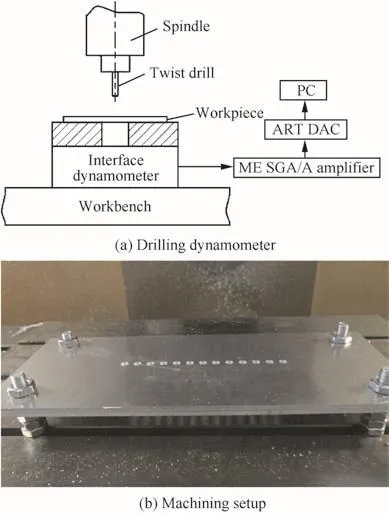
The drilling test is conducted on TH5660A machining center,the spindle speed ranges in 0–2500 r/min and the drilling style is dry cutting.Firstly,drilling thrust force is measured by dynamometer(see Fig.8(a)),then two aluminum plates are fixed on the workbench by four bolts with 8 mm diameter(see Fig.8(b))and drilling process starts.The thrust force measurement platform mainly contains an interface 1216-500/250 sensor from American,a PCI8510 data acquisition card from Chinese Art company,an SGA/A charge ampli fier from UK ME company,an A/D converter and a personal computer.

Fig.6 FEM model for interlayer gap with pressing force.

Table 1 Mechanical–physical properties of 7475 aluminum alloy.

Fig.7 Twist drill used in experiment.
The RETC white light interferometer is used to observe the burr morphology and measure the burr height.
4.3.Experimental design
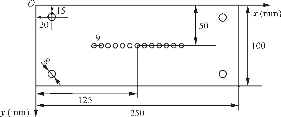
The experiment is designed into two parts.In part 1,the drilling experiment is conducted without preloaded pressing force.The experimental intent is to study the relationship of interlayer gap and interlayer burr height and analyze the effect of feed rate,thrust force and position of hole on interlayer burr height.Feed rate has a signi ficant effect on thrust force,as well as on interlayer burr formation,which indicates a possible correlation.31Based on the model of interlayer gap,the position of hole has a great effect on interlayer gap,as well as on interlayer burr.Each drilling test for different processing parameters is carried on a set of stacked plates.Firstly,four 8 mm diameter holes are made in the stacked plates,and then the stacked plates are fixed on the workbench.A row of 5 mm diameter holes every 9 mm for each set of process parameters are drilled inxdirection(see Fig.9).

Fig.8 Experimental platform.

Fig.9 Schematic of drilling holes.
In part 2,the experimental work is conducted with preloaded pressing force,and three holes are drilled for each group of processing parameter.The picture of drilling experimental setup with preloaded pressing force is shown in Fig.10.In the experimental setup,changing the air inlet direction of cylinder realizes the up and down movement of the piston.When the piston moves down,the pressure nose compresses the workpiece and drilling test starts.The preloading pressing force changes by adjusting the inlet pressure.The shape of analog pressure nose is a metal ring with inner radius 20 mm and external radius 25 mm.The purpose of drilling test is to study the in fluence of pressing force and feed rate on interlayer burr height and discuss the method to control interlayer burr height.

Fig.10 Drilling experimental setup with preloaded pressing force.

Table 2 Process parameters’settings for dry drilling stacked 7475 aluminum alloy plates.
In the experiment,the spindle speed is 2000 r/min,and the process parameters’settings are shown in Table 2.The interlayer exit burr height and interlayer entrance burr height of holes are measured at the periphery of hole in four orthogonal directions,and the arithmetic average of values is regarded as the ultimate value of interlayer burr height.

Fig.11 Effects on exit interlayer burr and entrance interlayer burr.

Fig.12 Interlayer burr morphology.
5.Results and discussion
5.1.Interlayer burr and interlayer gap without preloaded pressing force
The drilling burr formation mechanism is complicated and the drilling burr has various types depending on many factors,such as drilling parameters,material properties and temperature.And the occurring interlayer gap due to thrust force when drilling stacked metal materials has a signi ficant impact on interlayer burr.Fig.11 shows that feed rate is a signi ficant factor on interlayer burr height.Exit interlayer burr height increases with the increase of feed rate,while entrance interlayer burr height has little change.And entrance interlayer burr height is smaller than exit interlayer burr height,which is consistent with the situation that exit burr is larger than entrance burr when drilling single-layer aluminum plate.Fig.12 shows the interlayer burr morphology.And the change of interlayer burr via feed rate can be observed explicitly.When feed rate is small,exit interlayer burrs are large uniform burr and entrance interlayer burrs are small uniform burr,especially the size of entrance burr is slight.With feed rate increasing,the thickness and height of burrs are getting larger.

Fig.13 Comparison of experimental burr height and theoretical gap.

Fig.14 Effects of hole position on interlayer gap and interlayer burr.
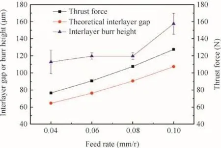
Smaller feed rate results in smaller thrust force and smaller bending deformation of stacked plates and it is helpful to obtain smaller interlayer gap,which is advantageous to the restraint of interlayer burr formation.In Fig.13,the interlayer burr height shows a positive correlation with feed rate and interlayer gap,and the interlayer burr height is larger than interlayer gap.Fig.14 shows the effect of hole position on plate surface on interlayer gap and interlayer burr at feed rate of 0.10 mm/r and spindle speed of 2000 r/min.From Fig.14,the further drilling hole is from the center of plate,the smaller mathematical interlayer gap,as well as the interlayer burr height,which validates that interlayer burr height has a positive correlation with interlayer gap.Moreover,the interlayer gap is smaller than interlayer burr height,and there are probably two reasons: firstly,the stacked plates are pre-connected by four bolts with uneven loading and the initial clearance exits before the drilling process,especially near the center of the plate,which cannot be considered in the mathematical model of interlayer gap;secondly,the plates should be separated during the measurement of interlayer burr height;under the effect of pressing force,the exit interlayer burr and the entrance interlayer burr are close together,which results in that the total interlayer burr height is larger than interlayer gap.

Fig.15 Interaction of pressing force and feed rate at interlayer burr height.

Fig.16 Effects of feed rate at burr height.
5.2.Interlayer burr and interlayer gap with preloaded pressing force
Based on the previous analysis,interlayer gap shows a positive correlation with interlayer burr height.Hence,the effective approach to decrease interlayer burr size is to reduce interlayer gap.And in robotic automatic drilling process,the main method is to preload pressing force by pressure nose.

Fig.17 Relationship between interlayer gap and interlayer burr height.
Figs.15 and 16 show the interaction of pressing force and feed rate on interlayer burr height.Obviously,when pressing force ranges from 0 N to 247.5 N,interlayer burr heights at all levels of feed rate decrease dramatically.Then with the increase of pressing force,the interlayer burr height at small feed rate decreases slightly,while the interlayer burr height at 0.10 mm/r of feed rate increases slightly,and totally the interlayer burr height is small and changes slightly.In Fig.16,when pressing force is less than 247.5 N,the effect of feed rate on interlayer exit burr height is obvious.However,when pressing force reaches 247.5 N,almost twice of thrust force at feed rate of 0.10 mm/r,the interlayer burr height changes with strong randomness,the exit interlayer burr height is less than 40 μm,the entrance interlayer burr height is about 10 μm and the total burr heights are less than 60 μm.It indicates that feed rate becomes a minor factor,while pressing force becomes the most signi ficant factor in fluencing interlayer burr height.In Fig.17,it shows that the changing tendency of interlayer burr height and interlayer gap are consistent and the interlayer gap is less than interlayer burr height.The interlayer gap decreases obviously with the increase of the pressing force,and then the interlayer gap decreases smoothly.When the pressing force reaches 165 N,the interlayer gap is less than 30 μm,but the interlayer burr height is about 100 μm at feed rate of 0.10 mm/r.Hence,in order to achieve small interlayer burr,the appropriate pressing force for this experiment is 247.5 N and the critical pressing force should be more than twice of thrust force.Given that the drilling force as well as interlayer burr height changes with the processing parameters,it needs future research to study the relationship between the critical pressing force and drilling force.
6.Conclusions
Aluminum alloy is widely used in aeronautical manufacturing industry due to its excellent properties.The need of automatic assembly of aircraft industry has pushed scienti fic institutions to develop a dry drilling process with small interlayer burr.The study on controlling interlayer burr height enables the following conclusions:
(1)The theoretical interlayer gap has a positive correlation with interlayer burr height,and the largest size interlayer gap,as well as the largest size interlayer burr,occurs near the center of plate.An effective way to inhibit interlayer burr is to control interlayer gap and the most common method is to preload pressing force.
(2)Feed rate has a signi ficanteffect on interlayer burr height;nevertheless,when pressing force is applied,the effect of feed rate is slight and pressing force becomes the most important parameter in fluencing interlayer burr height.And when the pressing force is more than 247.5 N,the control of interlayer burr is remarkable.
(3)It is worth of future research to find the optimal pressing
force considering the effect of drilling force.
The authors would like to gratefully acknowledge the financial support of the Aeronautical Science Foundation of China(Nos.2013ZE52067,2014ZE52057).
1.Zitoune R,Krishnaraj V,Collombet F.Study of drilling of composite material and aluminum stack.Compos Struct2010;92(5):1246–55.
2.Ramulu M,Branson T,Kim D.A study on the drilling of composite and titanium stacks.Compos Struct2001;54(1):67–77.
3.Zitoune R,Mansori ME,Krishnaraj V.Tribo-functional design of double cone drill implications in tool wear during drilling of copper mesh/CFRP/woven ply.Wear2013;302(1–2):1560–7.
4.Krishnaraj V,Zitoune R,Collombet F.Comprehensive review on drilling of multimaterial stacks.J Mach Form Technol2010;2(3–4):1–32.
5.Zitoune R,Krishnaraj V,Almabouacif BS,Collombet F,Sima M,Jolin A.In fluence of machining parameters and new nano-coated tool on drilling performance of CFRP/aluminium sandwich.Compos B Eng2012;43(3):1480–8.
6.Kim D,Sturtevant C,Ramulu M.Usage of PCD tool in drilling of titanium/graphite hybrid composite laminate.Int J Mach Mach Mater2013;13(2–3):276–88.
7.Zitoune R,Collombet F.Numerical prediction of the thrust force responsible of delamination during the drilling of the long- fibre compositestructures.ComposAApplSciManuf2007;38(3):858–66.
8.Gururaja S,Ramulu M.Modi fied exit-ply delamination model for drilling FRPs.J Compos Mater2009;43(5):483–500.
9.Tian W,Zhou WX,Zhou W,Liao WH,Zeng YF.Autonormalization algorithm for robotic precision drilling system in aircraft component assembly.ChinJAeronaut2013;26(2):495–500.
10.Bi SS,Liang J.Robotic drilling system for titanium structures.Int J Adv Manuf Technol2011;54(5–8):767–74.
11.Marguet B,Cibiel C,De Francisco O´,Felip B,Bernal J,Del Pozo J,et al.Crawler robots for drilling and fastener installation,an innovative breakthrough in aerospace automation.SAE technical paper;Report No.2008-01-2292.
12.Hellstern C.Investigation of interlayer burr formation in the drilling of stacked aluminum sheets[dissertation].Atlanta:Georgia Institute of Technology;2009.
13.Rivero A,Aramendi G,Herranz S,De Lacalle LNL.An experimental investigation of the effect of coatings and cutting parameters on the dry drilling performance of aluminum alloys.Int J Adv Manuf Technol2006;28(1–2):1–11.
14.Aurich JC,Dornfeld D,Arrazola PJ,Franke V,Leitz L,Min S.Burrs–analysis,control and removal.CIRP Ann Manuf Technol2009;58(2):519–42.
15.Melkote SN,Newton TR,Hellstern C,Morehouse JB,Turner S.Interfacial burr formation in drilling of stacked aerospace materials.Burrs–analysis,control and removal.Berlin:Springer-Verlag,Berlin Heidelberg;2010.p.89–98.
16.Bi SS,Liang J.Experimental studies and optimization of process parameters for burrs in dry drilling of stacked metal materials.Int J Adv Manuf Technol2011;53(9):867–76.
17.Kim J,Min S,Dornfeld DA.Optimization and control of drilling burr formation of AISI 304L and AISI 4118 based on drilling burr control charts.Int J Mach Tool Manuf2001;41(7):923–36.
18.Ko SL,Lee JK.Analysis of burr formation in drilling with a newconcept drill.J Mater Process Technol2001;113(1–3):392–8.
19.Park LW,Dornfeld DA.A study of burr formation processes using the finite element method:Part II–the in fluences of exit angle,rake angle,and backup material on burr formation processes.J Eng Mater Technol2000;122(2):229–37.
20.Min S,Dornfeld DA,Kim J,Shyu B.Finite element modeling of burr formation in metal cutting.Mach Sci Technol2001;5(3):307–22.
21.Saunders LKL.A finite element model of exit burrs for drilling of metals.Finite Elem Anal Des2003;40(2):139–58.
22.Segonds S,Masounave J,Songmene V,Be`s C.A simple analytical model for burr type prediction in drilling of ductile materials.J Mater Process Technol2013;213(6):971–7.
23.Kim J,Dornfeld DA.Development of an analytical model for drilling burr formation in ductile materials.J Eng Mater Technol2002;124(2):192–8.
24.Choi J,Min S,Dornfeld DA,Alam M,Tzong T.Modeling of inter-layer gap formation in drilling of a multi-layered material.Proc CIRP workshop on modeling of machining mcmaster;2003.
25.Li Y,Hu YX,Yao ZQ.Modeling and analysis of the effect of preloaded pressing force on gap formation during the drilling of double-layered material.Appl Mech Mater2012;217–219:1541–6.
26.Liang J.The formation and effect of the interlayer gap in dry drilling of stacked metal materials.Int J Adv Manuf Technol2013;69(5–8):1263–72.
27.Min S,Kim J,Dornfeld DA.Development of a drilling burr control chart for low alloy steel,AISI 4118.J Mater Process Technol2001;113(1–3):4–9.
28.Lauderbaugh LK.Analysis of the effects of process parameters on exit burrs in drilling using a combined simulation and experimental approach.J Mater Process Technol2009;209(4):1909–19.
29.Saunders LKL,Mauch CA.An exit burr model for drilling of metals.J Manuf Sci Eng2000;123(4):562–6.
30.Timoshenmko S,Woinowsky-Krieger S.Theory of plates and shells.2nd ed.New York:Mcgraw-Hill Book Company;1959.p.110–88.
31.Kilickap E.Modeling and optimization of burr height in drilling of Al-7075 using Taguchi method and response surface methodology.Int J Adv Manuf Technol2010;49(9):911–23.
 CHINESE JOURNAL OF AERONAUTICS2016年1期
- CHINESE JOURNAL OF AERONAUTICS的其它文章
- Plastic wrinkling prediction in thin-walled part forming process:A review
- Progress of continuously rotating detonation engines
- Microstructure control techniques in primary hot working of titanium alloy bars:A review
- A hybrid original approach for prediction of the aerodynamic coefficients of an ATR-42 scaled wing model
- Dynamic modeling and analysis of vortex filament motion using a novel curve- fitting method
- Boundary-layer transition prediction using a simpli fied correlation-based model
