Dynamic modeling and analysis of vortex filament motion using a novel curve- fitting method
Chang-Joo Kim,Soo Hyung Park,Sang Kyung Sung,Sung-Nam Jung
Department of Aerospace Information Engineering,Konkuk University,Seoul 05029,Republic of Korea
1.Introduction
The vortex approach still has large area of applications in aerodynamic loadprediction dueto its computational ef ficiency and its wide applicability in fixed-wing aircraft,rotorcraft,wind turbines,and others.1–7Helmholtz’s theorem of vortex motion and Kevin’s circulation theorem describe the basic physics on vortex flows in ideal- fluid.And,Kutta–Joukowski’s theoremof lift and Biot–Savart law8for induced-velocity field provide practical ways of both modeling and analyzing aerodynamic problems over lifting wings with vortex methods,among which the vortex lattice method(VLM)1–3and the free-vortex wake(FVW)method9–12combined with the blade element method(BEM)are widely used in many applications until now.These two methods commonly adopt a vortex filament model to meet Helmholtz’s theorem and the motion equation of vortex filaments are generally described with Lagrangian approach.7The VLM computes vortex strength by applying flow tangency condition at each control point distributed over wing surface and aerodynamic forces by applying Kutta–Joukowski’s theorem.Therefore,this method cannot consider the effect of viscous and compressible flow properties.Whereas,the FVW method combined with the BEM computes sectional lift,drag,and pitching moment using airfoil aerodynamic coef ficients.It utilizes the velocity induced by vortex filaments in computing local angle of attack and Mach number at each section of blade elements.The accuracy of aerodynamic loads predicted with both methods highly depends on the precision in computing both the motion of vortex filaments and the velocity induced by line vortex elements,which consist of main topics of this study.
This paper focuses on the application of curve- fitting techniques13in describing time-varying geometry of vortex filaments and in ef ficiently computing the line integral of Biot–Savart law with enough precision.In this regard,Bliss et al14used curved-vortex filaments in estimating an accurate line integration of Biot–Savart law.Their method allows coarser distribution of control points and claimed to reduce computing time without signi ficant loss of accuracy.Celi15proposed the use of the method of lines(MOL)to represent the motion equation of vortex filaments with the form of ordinary differential equations(ODEs)and analyzed system characters including system stiffness.His results showed that various ODE solvers can be selectable by considering numerical accuracy and ef ficiency.Recently,Liu16proposed an application of non-uniform rational B-spline(NURBS)curves to represent the geometry of vortex filaments.He transformed the motion equation for vortex filaments into ODEs using a NURBS-based interpolation.His work showed that the computation associated with the calculation of in fluence coef ficients and with time-marching free-wake analysis can be dramatically reduced for fixed-wing cases.Unfortunately,there is no proof of successful implementations of the proposed method for rotary wing problems.
This paper follows the similar approach to Liu’s.16Various curve- fitting techniques such as Be´zier-curves,B-spline,13and Lagrange interpolating polynomials17,18are investigated to select the best one among them.For this purpose,the dynamic characteristics of ODEs derived using each curve- fitting method are thoroughly analyzed by using the condition number of the mass matrix and the eigenvalues of the system matrix.Thereby,robustness and stability can be identi fied by analyzing the transformed ODEs.This kind of works has never been done in the previous researches including Liu’s study even though these characteristics are crucial in real applications.The natural choice of a line integral algorithm will be a quadrature formula with the curve- fitted geometric model of vortex filaments.However,singular nature in the kernel function of Biot–Savart law can cause dif ficulties in accurate computation of the induced velocity.A new type of integration strategy is proposed in this paper,where integration points are locally re fined with interpolating functions to remove fundamental causes of inaccurate prediction for a line integral.
The proposed methods are applied to time-marching freewake analyses for rotary wings.Various applications demonstrate the ef ficiency,accuracy,and flexibility of the proposed method and provide valuable information for the applications of the present approach.
2.Selection of interpolating curves for vortex filaments
Fee-vortex wake methods utilize the Lagrangian description for the motion of a trailed-vortex filament,where the filament geometry is represented by multiple-control points along the vortex-age coordinate ζ(t)as shown in Fig.1,whereV∞,Γ(t,ζ),r(t,ζ),and Ω represent the free-stream velocity,vortex strength,vortex-position vector and rotational speed of the rotor,respectively.
The time-varying geometry of vortex filaments can be described by the motion of each control point governed by the following equation7with a local velocity v,which is the sum of relative flow velocity and self-induced velocity due to the vortex system:

Since the vortex-age coordinate is a function of time,Eq.(1)can be reduced to Eq.(2):

The curve- fitting technique in general manner can be expressed by Eq.(3)using temporal position vectors rj(t)(j=0,1,...,n)and interpolating curves φj(t)(j=0,1,...,n).

wherenrepresents the total number of control points along the filament and rj(t)is the representative position vector ofjth control point.By substituting Eq.(3)into Eq.(2),the motion equation can be transformed into nonlinear ODEs for rj(t)as


The above equations can be rewritten in the matrix form16as
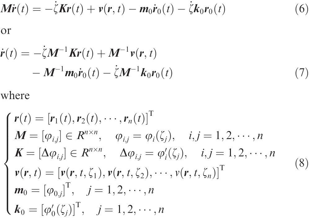
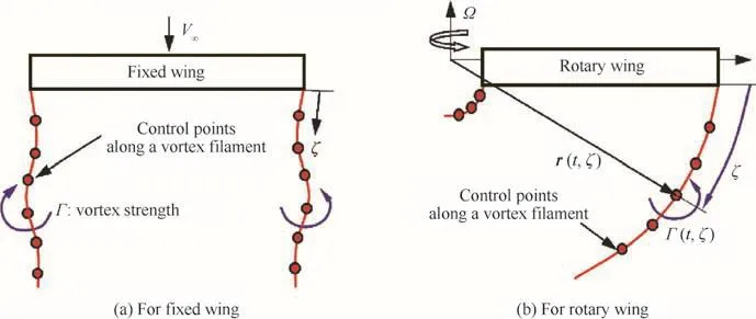
Fig.1 Vortex filament model for wing aerodynamics.
where M and K are the mass and stiffness matrices of the system,m0and k0are system vectors related to vortex release velocity and position,respectively.The point ζ0corresponds to the release point of the vortex filament and(r0,˙r0)denotes position and velocity vectors at that point.The system characteristics as shown in Eq.(7)directly depend on the matrices,M-1and K de fined by interpolating functions.Various factors should be considered in selecting interpolating functions.The most important one is its capability of accurately building the solvable ODEs with good system characteristics.The system sizenof Eq.(6)is determined by the minimum number of control points that are needed to represent the complex geometry of vortex filaments.
The de finitions of Be´zier curves,B-spline,and Lagrange interpolating polynomial are given in Table 1.Berstein polynomialBnj(τ)in Be´zier curves has the global support and the formula to calculate its function values and derivatives are well established.However,in case the number of control points is increased,the value of (1- τ)n-jτjapproaches to zero in the intermediate part of interval τ∈ (0,1).The matrix M in Eq.(6),therefore,becomes singular at an extreme case and large error can be involved in matrix inversion due to high condition number of the matrix M.The base-functions for B-spline curves have local supports and the parameter variable τ can be used without limitations in the range as in the Be´zier curves.The value of(t)becomes smaller and smaller as the orderkis increased.The effect of the number of knots(the number of τj)on the condition number of the matrix M must be carefully investigated even with a low order such as withk=2 ork=3.Since the NURBS inherits the characteristics of the B-spline,the curve fitting technique using the NURBS is expected to show the same behavior.Finally,the Lagrange interpolating polynomials φk(τ) computes φj(τk)= δjk(j,k=0,1,...,n)and its function value for τjis exactly the same as the physical variablefj.Therefore,Eq.(6)can be further simpli fied since M=I and m0=0,which exclude the effect of released velocity˙r0(ψ)of a vortex filament and the need of matrix inversion as shown in Eq.(9):

Table 2 compares condition numbers of the matrix M for different numbers of control points,where node points in the Lagrange interpolation are de fined using Legendre–Gauss–Lobatto(LGL)-type quadrature points.17,18In other cases nodes are uniformly distributed.As shown in the table the method based on Be´zier curves presents extremely high condition number at large node number.It indicates that the improvement of the spatial accuracy by increasing the number of nodes can be limited.Tables 3–5 show eigenvalues of matrix=M-1K which determines the system characteristics when local velocity approaches zero.With increasing node number,the motion equations generate unstable modes when built with B-splines.Since the number of eigenvalues with positive real part and the largest value among them are rapidly increasing,the B-spline method has a big disadvantage when a timemarching method is used to get a converged solution.It should be noted that the Lagrange interpolation method produces stable systems regardless of the node number.
From the above investigations the Lagrange interpolation polynomials are best suit to preserve good system characteristics for the present problems.Numerical analyses with it,however,can show slow convergence with large node number since the absolute value of the smallest negative real part is rapidly decreasing.Therefore,the use of local Lagrange interpolation polynomials is strongly recommended with a shift operator.If a required ordermof polynomials is given as an input,control points for interpolation are selected depending on the number of shiftsas given in Eqs.(10)and(11).

Table 1 Interpolating functions with an independent parameter τ.

Table 2 Condition number of matrix M.
Table 3 Eigenvalues of (n=4,ζmax=1.0).

Table 3 Eigenvalues of (n=4,ζmax=1.0).
?
Table 4 Eigenvalues of (n=8,ζmax=1.0).
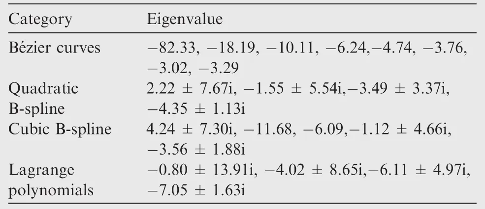
Table 4 Eigenvalues of (n=8,ζmax=1.0).
B-spline -4.35±1.13i Cubic B-spline 4.24±7.30i,-11.68,-6.09,-1.12±4.66i,-3.56±1.88i Lagrange polynomials-0.80±13.91i,-4.02±8.65i,-6.11±4.97i,-7.05±1.63i
Table 5 First 8-and 12-eigenvalues of in decreasing the order of real part (ζmax=1.0).
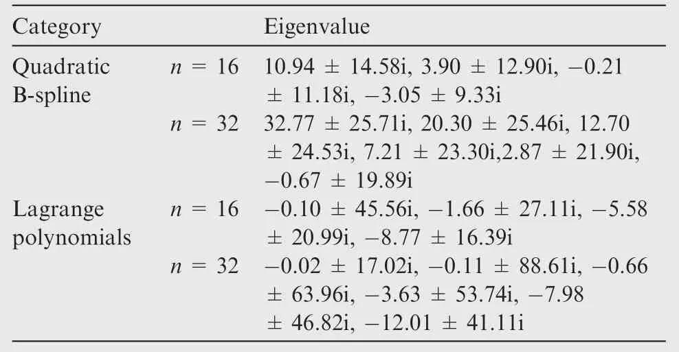
Table 5 First 8-and 12-eigenvalues of in decreasing the order of real part (ζmax=1.0).
Category Eigenvalue Quadratic B-spline n=16 10.94±14.58i,3.90±12.90i,-0.21±11.18i,-3.05±9.33i n=32 32.77±25.71i,20.30±25.46i,12.70±24.53i,7.21±23.30i,2.87±21.90i,-0.67±19.89i Lagrange polynomials n=16 -0.10±45.56i,-1.66±27.11i,-5.58±20.99i,-8.77±16.39i n=32 -0.02±17.02i,-0.11±88.61i,-0.66±63.96i,-3.63±53.74i,-7.98±46.82i,-12.01±41.11i
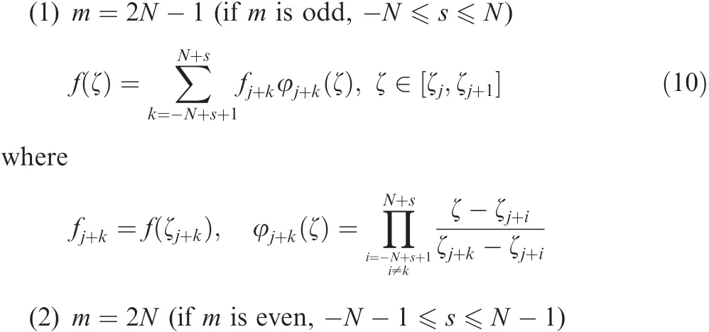
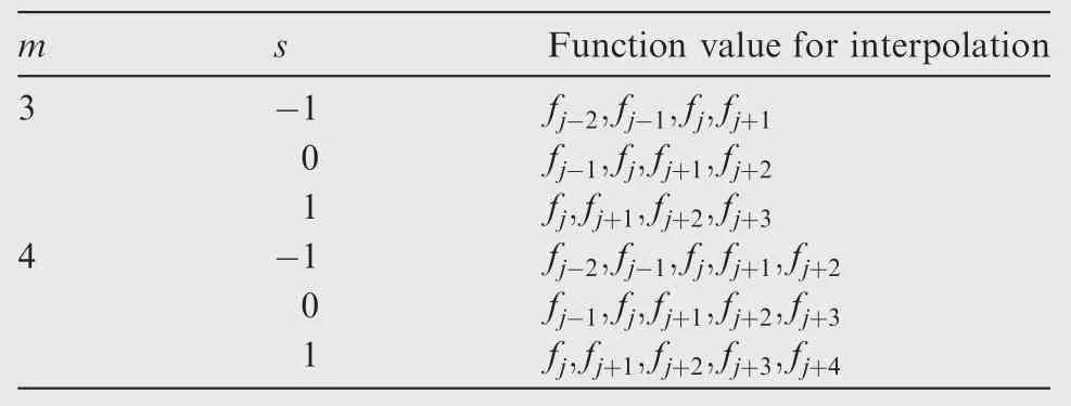
Table 6 Function values used for interpolation with s and m.

With the above strategy,function values at the interval ofa re interpolated using control points as examples given in Table 6.
Eigenvalues of K were investigated with both the order of interpolating polynomials and the number of shift operations,though not shown here.The investigation proves that the system can be destabilized whens≤0,which is conceptually similar to the use of upwind-algorithm for the numerical solution of wave equations to guarantee numerical stability.Moreinterestingly,any linearcombination of motion equations represented by the form of Eq.(9)can be used to enhance system characteristics as shown in Eq.(14)for two different systems,with α+ β =1.

3.Integration of Biot–Savart law
The motion equation of a vortex filament in Eq.(9)requires local velocity field v(r,t),some of which is contributed by the induced velocity due to vortex filaments.The induced velocity at a control point due to a line element along the vortex filament is determined by the Biot–Savart law.If we consideran in finitesimalline vortex elementdr with its circulation Γ(r)at a position r as shown in Fig.2,the induced velocity dvindat the control point rcdue to the vortex element can be written by the Biot–Savart law8as

Since the accurate line integration of Eq.(15)along the curved vortex filament is not an easy task,most applications utilize an approximated formula for a straight-line vortex element with a constant circulation.With reference to Fig.3,the mentioned formula can be expressed in a closed form as8
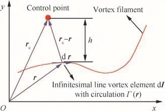
Fig.2 Curved vortex filament model for Biot–Savart law.
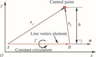
Fig.3 Straight-line vortex filament model with a constant circulation.
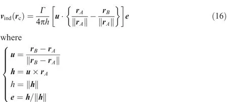
Ashapproaches toward zero,Eq.(16)shows a singular behavior and this is commonly removed using a viscous core model7with radiusrclike

Various comparative studies on the accuracy of the induced velocity using straight-segment models have been carried out for vortex rings and helical vortices as in Refs.19,20For a vortex filament with large curvature variation,the extremely fine distribution of control points is required for an accurate computation of the induced velocity.
A line integration method using quadrature formula as an alternative is investigated and is considered to be a natural choice for the curve- fitted geometry of a vortex filament.Line integral at an interval can be written using Gauss quadrature formula17,18with its quadrature pointsskand weightswk(k=1,2,···,nG)asalong a vortex filament

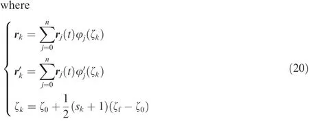
Since the kernel function shows highly nonlinear behavior as the control point approaches to a vortex filament,it is difficult to determine the required number of integration points.To clarify this issue the velocities induced by a straight-line vortex element and by a ring vortex are thoroughly investigated in this paper.
Fig.4 illustrates a straight-line vortex model and the control point location de fined with normal distancehand rotation angle θ.In case the vortex strength Γ is a constant,Eq.(16)provides the exact integration of the Biot–Savart law at the control point.Fig.5 compares the normal component of induced velocitiesvcomputed by using Eq.(18)with the exact solution when the quadrature formula uses 12 nodes distributed over the vortex filament.The results show that the accuracy is deteriorated ash/Lbecomes smaller than 0.1.Fig.6 shows the analytical results forh/L=0.01 with 4-point quadrature formula for different numbers of vortex elements(Ne)along the filament.Highly re fined vortex elements can recover the accuracy of the integration,in case of which computation time is rapidly increasing.An ef ficient computation with the quadrature formula,therefore,requires a strategy for local node re finement with an adequate length scale for good accuracy.From the above results,the normal distanceh/Ldirectly affects the accuracy of the line integration and can be a measure for the node re finement strategy.In case the distanceh/Lfor a line vortex element is greater than a given length scale,the Gauss quadrature formula can provide an accurate result.Otherwise,the element is split into smaller vortex elements,the number of which depends on the required accuracy,and the exact formula shown in Eq.(16)can be applied for each element.Points for the line-vortex splitting can be accurately positioned using curve- fitting techniques,whereas an adequate length scale for the algorithm switching needs careful selection depending on problems to resolve.
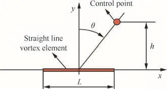
Fig.4 Straight-line vortex element and control point location.
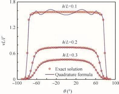
Fig.5 Induced velocity with normal distance.
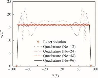
Fig.6 Induced velocity with the number of vortex elements(Ne).
Fig.7 represents a ring vortex placed in thex–yplane and the corresponding straight-line vortex model with the evenly spaced 6 control points.The induced velocity at each point in 3D space can be represented by complete elliptic integrals of the first and the second kinds as given in Ref.21Fig.8 illustrates the error sources in the induced velocity prediction when a straight-line vortex model is used.The curved-vortex filament model can compute a realistic distribution by correctly positioning the singular point.However,in case the quadrature formula is adopted,the induced velocity prediction highly depends on the quadrature distribution of nodes.As shown in Fig.9,the nodes of Types①and②,which have relatively larger normal distance than that of Type③,cannot compute the singular behavior in the induced velocity distribution across the curved-vortex filament.Therefore,there exist pros and cons in each method.
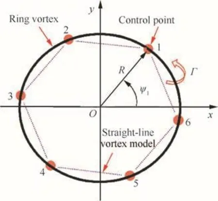
Fig.7 Ring vortex model with 6-control points.
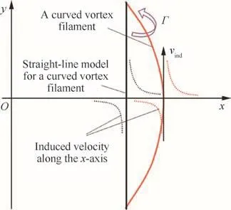
Fig.8 Schematic view of change in singular point along the x-axis depending on vortex filament model.
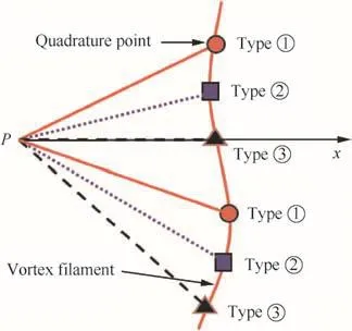
Fig.9 Different types of quadrature node distribution for induced velocity prediction.
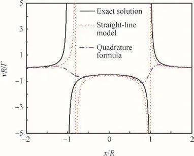
Fig.10 Induced velocity prediction for a ring vortex with 5 elements(ψ1=0).
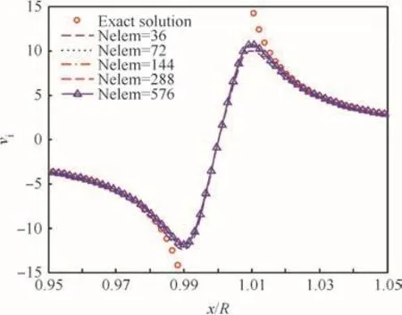
Fig.11 Induced velocity prediction with straight-line vortex model(rc/R=0.01).
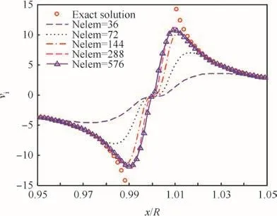
Fig.12 Induced velocity prediction for curved vortex filament with quadrature formula(rc/R=0.01).
Fig.10 compares the prediction between the straight-line model and the quadrature formula for a ring vortex with 5 line-segments.The straight-line model shows large positioning error at the singular point,as expected.The quadrature formula weakens the singular nature in the induced velocity distribution.However,it shows more accurate prediction than that with the straight-line model when the distance from the vortex filament is increased.Figs.11 and 12 display the effect of the number of line vortex elements(Nelem)on the predicted induced velocityvi,where computations utilize the viscous core model withn=2 andrc/R=0.01 in Eq.(17).The straight-line model shows nearly the same results for all element numbers ranging from 36 to 576.Fig.12 denotes that the line integration using the quadrature formula should be applied to over 576 elements for an accurate computation of tangential velocity.In order to recover both the accuracy and the ef ficiency in computing the induced velocity with the quadrature formula,we propose the local re finement strategy with the line-vortex model.As shown in Fig.12,the core radius can be used as a reference length scale for the ring vortex and the present quadrature formula can provide an accurate prediction when the distance from the filament is greater than 4rc.Since the normal distancehde fined in Fig.4 can be a measure of nonlinearity in the kernel function from previous analyses of the straight-line vortex element,the ratioh/rcis used to control the re finement of node points.For a given switching parameter,^h,the following strategy is applied in this paper:
(1)In case of^h≥h/rcfor all quadrature nodes over a linevortex segment,the quadrature formula is applied.
(2)Otherwise,the exact formula for a straight-line vortex element is used after the corresponding line vortex segment is divided into the speci fied number of straightline vortex elements.
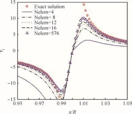
Fig.13 Induced velocity prediction using straight-line formula(rc/R=0.01).
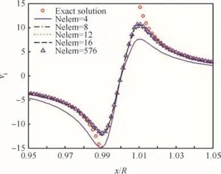
Fig.14 Induced velocity prediction with local re finement(rc/R=0.01).
Fig.13 shows the effect of vortex element numbers on the induced velocity calculation using the straight-line formula and Fig.14 displays the effect of the present local re finement strategy with 2-point quadrature formula,where the nondimensional normal distance is given by^h=20 and the line vortex element is re fined with 10 elements whenever the condition(1)is not met.The results show the high accuracy can be obtained even with 8-line vortex segments for the ring vortex.It is obviously indicated that the present local re finement is more ef ficient than the conventional straight and curved filament models.
4.Applications to rotary wing problems
This work mainly focuses on dynamic modeling of the vortex filament with a curve- fitting technique and tries to minimize the complexity related to modeling of aerodynamic loads and core radius growth,etc.Fig.15 shows a 4-bladed rotor model with the angular velocity Ω,where the trailed-wake system is modeled only with tip-vortex filaments trailed from each blade tip.The motion equation of vortex filaments given in Eq.(2)can be rewritten as Eq.(21):
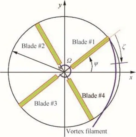
Fig.15 Tip vortex filament model for rotary wing.

where ψ = Ωtis the azimuth angle and= Ω(t-t0)vortex age coordinate.t0denotes the time of tip vortex release.~v=v/ΩRand=r/Rare the non-dimensional velocity and the nondimensional vortex filament position,respectively.
The first application is to show the importance of system stability in the analyses with the curve- fitting technique.Fig.16 shows the initial tip vortex geometry,radially stretched out from each blade tip to 1.5Rposition.For hovering flight with zero vortex-strength,the exact geometry of each vortex filament should be a circle after finite number of rotor revolutions.For the purpose of analyses following two system equations with the 4th order Lagrange interpolating functions are de fined with different shift operations and parentheses denote the eigenvalue which has the largest real part.
As previously mentioned,the linear combination of these two system matrices can generate a system dynamics as
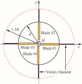
Fig.16 Initial tip vortex geometry.

The eigenvalues of three systems generated with α of 1.0,0.2,and 0.3 were computed:-1.0135–3.0488i,0.8246+3.6487i,and 1.0695+3.4802i,respectively.The system with α=1.0 is stable but the others are unstable.The analysis is carried out with 18 control points evenly distributed along the vortex filament with its maximum vortex age angle of 360°and the 4th order Runge–Kutta time integration method is adopted with time step size of Δψ =1.0°.The results shown in Fig.17 displays the control effect of the system stability with α.The forward portion of the vortex filament with small ζ is highly in fluenced by this stability character and rapidly propagates irregular motion into the downward part of the filament.Fig.18 represents the effect of the number of control points per one rotor revolution on the steady-state vortex geometry obtained after 10 rotor revolutions.Even with relatively smaller number of control points(18 and 24 points),the present method can compute nearly the same vortex geometry with the exact circular shape.
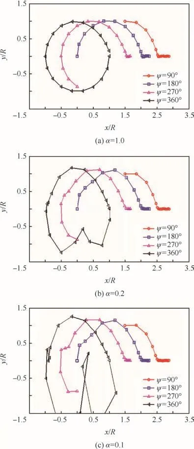
Fig.17 Tip vortex geometry for Blade#1.
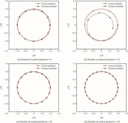
Fig.18 Tip-vortex geometry for Blade#1 with varying number of control points per one rotor revolution(/rev).
The second application to rotary wing problems is to consider the effect of vortex strength.For simplicity the twobladed rotor(Nb=2)is assumed to have a constant vertical climb speedVc(Vc/ΩR=0.01-0.07)and to undergo the step change in circulation at the start of 5th rotor revolution.If not speci fically mentioned,the following data are given:initialcirculationis0.02,vortexcoreradiusrc/R=0.0001,time step size Δψ =2π/72 rad,spatial step size 2π/36 rad/rev.The vortex system of rotors consists of tip-vortex filaments,bound vortices and one root vortex,which is assumed to be stretched vertically downward along the rotating axis in order to minimize computational effort.In this case,the strength of the circulation of each vortex element becomes twice of the given initial value after 5 revolutions of the rotor.
The momentum theory can provide a physical insight into this problem.From Kutta–Joukowski’s theorem,7,8the lift contribution to the trust coef ficientCTdue to bound vortices with constant circulation can be derived as
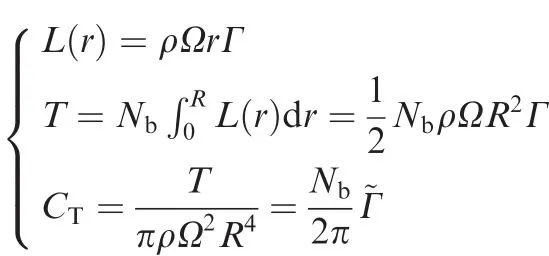

whereviandvhare the normal component of induced velocity and the uniform induced velocity at hover.Eq.(23)provides a uniform variation of the in flow.
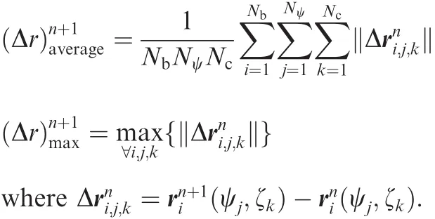
Since the vortex filament motion is generally understood to be unstable at near hover and decent flight cases,various measures for motion characteristics are helpful to investigate time evolution of vortex filaments.Time history of the filament position can provide information on its geometric convergence and unsteadiness.For this purpose,the mean and maximum correction in positions of control points are de fined for each rotor revolution as
The asymmetric feature of the filament geometry can be measured using the following parameters.
(1)Maximum asymmetric deviation inOxyplane for twobladed rotor:

(2)Degree of asymmetry in number of control points,which presents Δaj,k≥ Δatolerance,for a speci fied Δatolerance(=0.01R in the present study).
Finally,the minimum distance between vortex filaments can show the degree of nonlinearity in the induced velocity due to their closeness and it can be estimated by the minimum distance among control points.
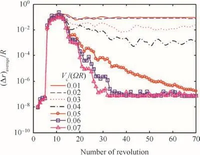
Fig.19 Average correction of tip vortex geometry.
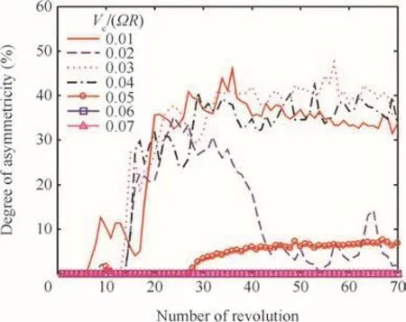
Fig.20 Degree of asymmetric feature in tip vortex geometry.
Figs.19–21 show the history of geometric measures of vortex filaments,where the motion equation is integrated in timemarching manner using the 5th order Runge–Kutta time integration method.22–24Fig.19 shows convergence of the average correction of tip vortex geometry.The fully-converged tip vortex geometry can be achieved withVc/(ΩR)≥ 0.0475 but the converged geometry is asymmetric as shown in Fig.21.For lower climb speeds oscillatory corrections are continuously added to the vortex path.Fig.20 presents fully converged symmetric geometries after 70 rotor revolutions can be obtained for the range of climb speedVc/(ΩR)≥ 0.06,which is greater than the uniform in flow at hover.As climb speed decreases,the degree of asymmetry abruptly increases up to 40%and the minimum distance between two vortex filaments becomes extremely close.The present simulation results are in7good agreement with the previous observation.Leishman mentioned that aperiodic motion of vortex filaments comes from natural instability modes of a helical vortex system.Accurate numerical simulation of unstable behavior of vortex- filament motion may require complex algorithms that can adaptively control time-step size depending on the minimum distance among filaments.The present full timemarching techniques without any under-relaxation,however,provide fast convergence to a steady state for the present case.
The applications of the free-wake model to the rotorcraftaerodynamic problems require a realistic structural model forthe vortex system and the consideration of the real flow effectsto accurately predict blade air-loads.7For this purpose, theBEM is typically combined with the FVW model to considerthe nonlinear aerodynamic effect due to both viscosity andcompressibility effects.6,25,26A vortex structure shown inFig.22is used for the applications of the present methods.The detailed models to determine the vortex strengths of thenear and tip wakes are well described in Ref.25and the solutiontechniques for the coupled BEM-FVW analyses are also presentedin Ref.26The proposed methods are applied to theair-load prediction of the two-blade rotor model27, and theauthor’s analysis programs (HETLAS) as introduced throughRefs.28–30are used for predicting the rotor air-load includingthe table lookup of airfoil-section aerodynamic data. For thehovering rotor, the air load at a blade element with the radialposition r and the geometric pitch θ can be computed using thelocal induced velocity vi predicted with the wake analysis andthe tangential velocity Ωr due to the rotor rotation as
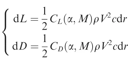

An iterative solution process is adopted to get a converged solution for both wake structure and air load.
Fig.23 shows the predicted thrust and power coef ficientsCTandCPwith the variation of the collective pitch and the angle of the near wake filaments extended from the trailing edge of the airfoil.The core radii of the near wakes are set to be 1.5 times of the averaged width of each blade element and those of the tip wake are modeled using the correlated Iverson’s formula6with the core growth factor δ =1000.The tip vortex filaments are extended to the 7 rotor revolutions and the tip vortex release point is fixed at the 25%chord of the tip airfoil section.The detailed rollup process of tip vortex filaments is ignored and the position of the inboard wake filament is de fined using the prescribed wake model described in Ref.6
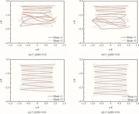
Fig.21 Tip vortex geometry after 70 rotor revolutions.
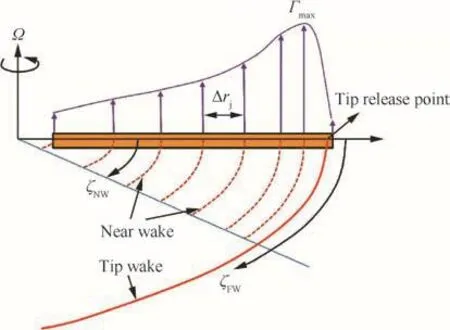
Fig.22 Schematic structure of vortex system over a blade.25
The blade is divided into 30 elements using the equal annular area concept for the BEM and the 36 nodes per rotor revolution are uniformly distributed along each vortex filament.These modeling parameters and features are commonly used for all follow-on analyses if not speci fically mentioned.The predicted aerodynamic coef ficients show a similar trend to the measured and computed data given in Ref.27However,the extension angle of the near wake highly affects the predicted aerodynamic performance.The predicted air-load distributions around blade root are highly affected by the extension angle of the near wake as presented in Figs.23 and 24.A reasonable value for the near wake extension angle may be given31,although not tried in this study.The over-predicted lift coef ficients around the tip region indicate that the models for the detailed formation process and the flow structure of the tip vortex filaments need to be re fined.The discrepancy in the tip vortex trajectory,shown in Fig.25,can supplement this point and the prescribed inboard wake model used in this study needs further re finement.
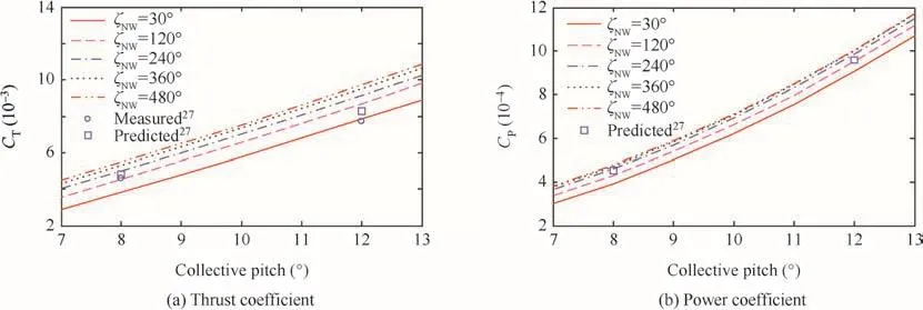
Fig.23 Predicted thrust and power coef ficients for Caradonna and Tung’s model(θc=8°,RPM=1250).
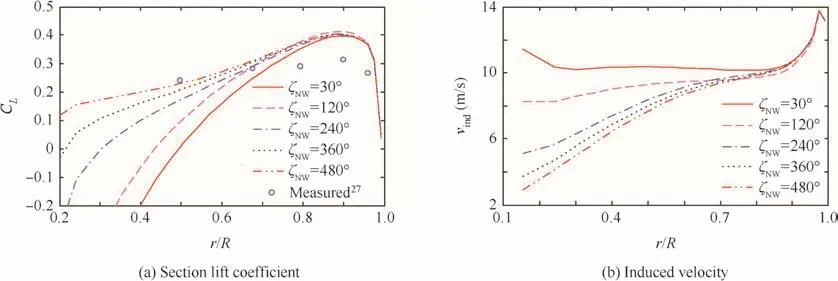
Fig.24 Predicted distribution of air-loads and induced velocity.
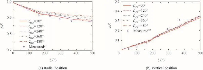
Fig.25 Predicted tip vortex trajectory.
5.Conclusions
The use of local Lagrange interpolating polynomials with shift operation is proposed to describe the dynamics of the vortex filament.Lagrange interpolating polynomials can provide the equation of motion for vortex filaments with superior system properties to other curve- fitting methods,such as Be´zier curves and B-spline(including NURBS).The applications of this approach show that the unsteady motion of the vortex filament can be estimated with the full timemarching techniques without any under-relaxation method,which can provide fast convergence in steady-state problems.The positioning of the singular point near the vortex filament and the induced velocity due to a general curved vortex filament are well predicted by the quadrature formula coupled with the local node re finement strategy in the present work.Ef ficiency in computing the induced velocities at each control point can be greatly enhanced when the line integration of the kernel function is computed by the quadrature formula to the curved vortex filament model.Furthermore,the curved vortex filament model can accurately describe the unsteady wake geometry with much less number of states than the straight-line model that saves the computational time.
Applications to the rotary wing have been successfully carried out with the time-marching technique without relaxation strategy.The tip vortex geometry can be accurately estimated even with 18 control points per revolution using the proposed method.To validate the usefulness the present methods are applied to the prediction of the aerodynamic performance and the distribution of aerodynamic loads and induced velocities along the blade span for the two-bladed rotor.The proposed vortex models are successfully implemented into the blade element method to consider the nonlinear aerodynamic characteristics.The computed air-load distribution is comparable to those of the experimental data.The parametric studies on the near-wake extension angle show that the extension angle highly affects the air loads around the inboard portion of the blade.The results show that the present methods are robust enough to compute the complex flow fields with the strong blade-vortex interaction.The analyses for highly distorted rotor wakes at low and high forward speeds can also enjoy advantages gained by the proposed methods with much less nodes than those required for the straight line vortex elements.The proposed techniques,therefore,can be used to solve the rotorcraft aeromechanic problems in the ef ficient and accurate manner.
Acknowledgement
This research was supported by the EDISON Program through the National Research Foundation of Korea(NRF)funded by the Ministry of Science,ICT and Future Planning(No.2011-0020560).
1.Kier T,Looye G,Hofstee J.Development of aircraft flight loads analysis models with uncertainties for pre-design studies.International forum on aeroelasticity and structural dynamics.2005.
2.Levin D.A vortex-lattice method for calculating longitudinal dynamic stability derivatives of oscillating delta wings.AIAA J1984;22(1):6–12.
3.Sequeira CJ,Willis DJ,Peraire J.Comparing aerodynamic models for numerical simulation of dynamics and control of air-craft.Reston:AIAA;2006.Report No.:AIAA-2006-1254.
4.Vargas LA,Oliveira PH.A fast aerodynamic procedure for a complete aircraft design using the known airfoil characteristics.New York:SAE;2006.Report No.:SAE 2006-01-2818.
5.Jansen PW.Aerostructural optimization of non–planar lifting surfaces[dissertation].Toronto:University of Toronto;2009.
6.Leishman JG,Bhagwat MJ,Bagai A.Free-vortex filament methods for the analysis of helicopter rotor wakes.J Aircraft2002;39(5):759–75.
7.Leishman JG.Principles of helicopter aerodynamics.2nd ed.New York:Cambridge University Press;2006.p.567–645.
8.Karamcheti K.Principles of ideal- fluid aerodynamics.New York:John Wiley and Sons;1966.p.524–39.
9.Bhagwat MJ.Transient dynamics of helicopter rotor wakes using a time-accurate free-vortex method [dissertation].Maryland:University of Maryland;2001.
10.Bhagwat MJ,Leishman JG.Stability,consistency and convergence of time-marching free-vortex rotor wake algorithms.J Am Helicopter Soc2001;46(1):59–71.
11.Bhagwat MJ,Leishman JG.Accuracy of straight-line segmentation applied to curvilinear vortex filaments.J Am Helicopter Soc2001;46(2):166–9.
12.Bhagwat MJ,Leishman JG.Generalized viscous vortex models for application to free-vortex wake and aeroacoustic calculations.Proceedings of the 58th annual forum of the American Helicopter Society.Alexandria:American Helicopter Society;2002.
13.Prautzsch H,Boehm W,Paluszny M.Be´zier and B-spline techniques.Berlin:Springer;2002.p.9–22.
14.Bliss DB,Teske MF,Quackenbush TR.A new methodology for free wake analysis using curved vortex elements.Washington,D.C.:NASA;1987.Report No.:NASA CR-3958.
15.Celi R.State-space representation of vortex wakes by the method of lines.J Am Helicopter Soc2005;50(2):195–205.
16.Liu H.Interfacing comprehensive rotorcraftanalysiswith advanced aeromechanics and vortex wake models[dissertation].Atlanta:Georgia Institute of Technology;2008.
17.Canuto C,Hussaini MY,Quarteroni A,Jang TA.Spectral methodsin fluid dynamicsSpringerseriesincomputational physics.Berlin:Springer-Verlag,Berlin Heidelberg;1988.
18.Fahroo F,Ross IM.Costate estimation by a Legendre Pseudo-Spectral method.J Guidance Control Dyn2001;15(2):270–7.
19.Gupta S,Leishman JG.Accuracy of the induced velocity from helicoidal wake vortices using straight-line segmentation.AIAA J2005;43(1):29–40.
20.Wood DH,Li D.Assessment of the accuracy of representing a helical vortex by straight segments.AIAA J2002;40(4):647–51.
21.Yoon SS,Heister SD.Analytical formulas for the velocity field induced by an in finitely thin vortex ring.Int J Numer Meth Fluids2004;44(6):665–72.
22.Hairer E,Nørsett SP,Wanner G.Solving ordinary differential equations I:nonstiff problems.Springer series in computational physics.2nd ed.Berlin:Springer-Verlag,Berlin Heidelberg;1993.
23.Butcher JC.On fifth-order Runge-Kutta methods:order conditions and order barriers.Can Appl Math Q2009;17(3):433–45.
24.Radwan FAA.Solutions of initial value problems using fifth-order Runge-Kutta method using excel spreadsheet.Pakistan J Appl Sci2002;2(1):44–7.
25.Kim CJ,Kim SH,Park TS,Park SH,Lee JW.Flight dynamic analyses of propeller-driven airplane(I):aerodynamic and inertial modelling of propeller.Int J Aeronaut Space Sci2014;15(4):345–55.
26.Kim CJ,Kim SH,Park TS,Park SH,Lee JW.Flight dynamic analyses of propeller-driven airplane(II):building a high- fidelity mathematical model and applications.Int J Aeronaut Space Sci2014;15(4):356–65.
27.Caradonna FX,Tung C.Experimental and analytical studies of a model helicopter rotor in hover.Washington,D.C.:NASA;1981.Report No.:NASA-TM-81232.
28.Yun YH,Kim CJ,Shin KC,Yang CD,Cho IJ.Building the flight dynamic analysis program,HETLAS,for the development of helicopter FBW system.1st Asian Australian rotorcraft forum and exhibition;2012.
29.Kim CJ,Shin KC,Yang CD,Cho IJ,Interface features of flight dynamic analysis program,HETLAS,for the development of helicopter FBW system.1st Asian Australian rotorcraft forum and exhibition;2012.
30.Kim CJ,Sung SK,Park SH,Jung SN,Park TS.Numerical timescale separation for rotorcraft nonlinear optimal control analyses.J Guid Control Dynam2014;37(2):658–73.
31.Bagai A.Contributions to the mathematical modelling of rotor flow- fields using a pseudo-implicit free-wake analysis[dissertation].Mary-land:University of Maryland;1995.
 CHINESE JOURNAL OF AERONAUTICS2016年1期
- CHINESE JOURNAL OF AERONAUTICS的其它文章
- Plastic wrinkling prediction in thin-walled part forming process:A review
- Progress of continuously rotating detonation engines
- Microstructure control techniques in primary hot working of titanium alloy bars:A review
- A hybrid original approach for prediction of the aerodynamic coefficients of an ATR-42 scaled wing model
- Boundary-layer transition prediction using a simpli fied correlation-based model
- Aeroelastic scaling laws for gust load alleviation control system
