A novel biased proportional navigation guidance law for close approach phase
Su Wenshan,Yao Dangnai,Li Kebo,Chen Lei
College of Aerospace Science and Engineering,National University of Defense Technology,Changsha 410073,China
1.Introduction
The traditional proportional navigation guidance(PNG)laws1–3mainly regard zero miss distance as the primary goal.While accompanying the emergence of diverse space missions,making the spacecraft rendezvous with the target in speci fic relative range and direction becomes a new expected guidancegoal.4–6One case for example is the space debris removal based on the technology of flexible on-orbit capture.4The capture equipment of space debris is carried by spacecraft and released when spacecraft rendezvous with the space debris.The desired releasing position relative to debris is determined by the optimal operational range and direction of capture equipment.4In order to guide the spacecraft to the desired position with considerable relative closing speed,appropriate guidance law should be resorted to at the close approach phase.
The biased proportional navigation guidance(BPNG)law,as one of PNG modi fications,has been studied for a long time.BPNG was proposed in Ref.1firstly,and in such a form that a bias term designed was superimposed on the commanded acceleration of PNG.Previous investigations on BPNG mainly focus on two categories:(1)improving the performance of PNG;(2)ful filling special guidance goals.One pioneering work of the first category is to eliminate the oscillation of lineof-sight(LOS)rate caused by sensor noise under PNG.1Another aspect of the same category is to improve the control-effort ef ficiency of PNG and expand the capture region of PNG against maneuver targets.7–9In the second category,one pioneering work is to achieve the special impact angle.10Because of the small angle assumptions and a linearized dynamics in Refs.10,11,the designed BPNG had the drawbacks of narrow lunch envelope and very restricted capture region.To overcome these drawbacks,In Ref.12,a BPNG is designed using a nonlinear engagement model.Taking more realistic interception situations into account,BPNGs with robustness on seeker noise and velocity change and limitation on acceleration capability are designed in Refs.13,14Furthermore,BPNG with impact time and angle constraints15is also studied.
According to the above introduction,the guidance problem of rendezvousing in speci fic relative range and direction can be classi fiedintothesecondcategoryofBPNG.However,theguidancegoaliscompletelydifferentfrompreviousBPNGs.Besides,BPNGs mentioned above were structured in two-dimensional(2D)space,while the practical rendezvous between the spacecraft and target happens in three-dimensional(3D)space.In Refs.16–18,3D relative motion was analyzed by extending the concept of‘unit relative angular momentum” to 3D space and introducing a new coordinate system,wherein the 3D relative dynamic equations were derived,with the advantage of decoupling the radial motion from the tangential motion.Tyan19–21extended the uni fied approach to PNG22in 3D space by using modi fied polar coordinates and the corresponding relative dynamic equations.Based on the classical differential geometry curvetheory,Lietal.23–26derivedasetofrelativedynamicequations between interceptor and target,which is characteristic of decoupling the relative motion in the instantaneous rotation plane of LOS(IRPL)from the rotation of this plane.3D BPNG in this paper is designed based on the LOS rotation coordinate system and relevant variables as used in Ref.25And the BPNG deduced in this paper is not only able to guide the spacecraft to reach the desired releasing position,but also with the advantage of avoiding the accidental collision between the spacecraft and target.
The control-effort ef ficiency is also an important objective for guidance law designs.Taking the control-effort ef ficiency into account,this paper derives the optimal BPNG(OBPNG)by employing Schwartz inequality,which has been used by Zarchan27for deriving the optimal PNG and trajectory shaping guidance law with impact angle constraints.

Fig.1 Line-of-sight(LOS)coordinate system.
2.Problem description
2.1.Geometric model
In the scenario of rendezvous between spacecraft and target,the geometric model is described in the LOS coordinate systemo1xsyszs,whose original point is centered at the spacecraft’s mass center,as shown in Fig.1.The LOS azimuth angle βsand LOS elevation angle εsdescribe the relationship betweeno1xsyszsand the coordinate systemo1xyzwhich is parallel to the inertial coordinate system.The inertial coordinate system is de fined at the beginning of the close approach phase and with the origin fixed at the initial position of spacecraft,thex-axis points to the initial direction of LOS,theys-axis is vertical toxs-axis and lies in the plane which is vertical to the local horizontal plane,thez-axis satis fies the righthanded coordinate rule with respect tox-axis andy-axis.The coordinate systemo1x′y′z′in Fig.1 denotes the interim coordinate system during obtainingo1xsyszsby rotatingo1xyz.
The relative motion between the spacecraft and target is illustrated in Fig.2.The variables vm,vtand v represent the velocity vector of spacecraft,the velocity vector of target and the relative velocity vector,respectively.φ indicates the angle between v and LOS.During the process of approaching,if both the spacecraft and target do not maneuver,the relative position vector is de fined as the zero effort miss vector ZEM*when the spacecraft rendezvous with the target.And the magnitude of ZEM*could be described as

where ZEM*is the magnitude of ZEM*and ZEM the magnitude of ZEM,which is vertical to LOS,as shown in Fig.2.φ is usually a small angle before the seeker of the spacecraft enters the blind area where the guidance system usually stops working.Therefore,ZEM*could be approximated by ZEM during most of the guidance process.
Combining with the de finition of the LOS coordinate system,ZEM is parallel toyso1zsplane as expressed in Fig.3.The variables ZEMbiasys,ZEMys,ZEMbiaszsand ZEMzsare the corresponding components of ZEM and ZEMbiasalongys-axis andzs-axis.The angle γ and the magnitude of ZEM denote the relative orientation and range when the spacecraft rendezvous with the target,respectively.The expression of ZEM is

where r is the relative position vector,ωsthe LOS rate,tgothe time to go which could be approximated byr/|˙r|,withrthe magnitude of r.Since ωsis always vertical to r,the magnitude of ZEM can be expressed as ZEM=rωstgo,with ωsthe magnitude of ωs.
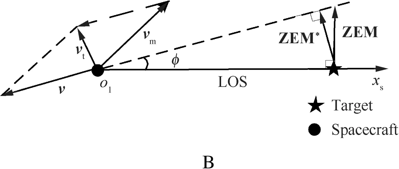
Fig.2 Relative motion between the spacecraft and target.

Fig.3 Biased zero effort miss vector in LOS coordinate system.
2.2.Guidance goal
As stated in the introduction,the guidance goal of the special rendezvous is to guide the spacecraft to the desired position.In the LOS coordinate system,the desired position can be described by the biased zero effort miss vector ZEMbias,as shown in Fig.3.The magnitude of ZEMbiasand its orientation angle γbiasrepresent the relative range and direction of desired position,respectively.The guidance goal is to make ZEM approach ZEMbias.
The primary guidance goal of arriving at the desired position may not be suf ficient because the safety of the spacecraft and target should also be taken into consideration.In other words,during the close approach phase,the accidental collision between the spacecraft and target should be avoided.For the sake of convenience,it is necessary to set the dangerous area where collision risks exist.One conservative de finition of dangerous area is depicted in Fig.4.The spherical dangerous area is centered at the centroid of the target,and its radiusrareais the sum of envelope radiuses of the spacecraft and target.By comparing the magnitude of ZEM withrarea,it is easy to make a reasonable prediction about the collision risk.Due to the approximation between ZEM*and ZEM,it is acceptable to replace ZEM*with ZEM and make an equivalent prediction of the collision risk for simplicity.
One condition with potential collision threat during the approach phase is shown in Fig.5.The circle centered at origino1is the projection of the dangerous area on theyso1zsplane.The positions of ZEM and ZEMbiasin theyso1zsplane are depicted in Fig.5.If ZEM approaches ZEMbiasalong the dotted line,ZEM will cross the circle and its magnitude will be smaller thanrareawhen ZEM is inside the circle,which means potential collision risk.Therefore,considering the safety,the guidance law designed must have the ability to evade the dangerous area during the approach phase.
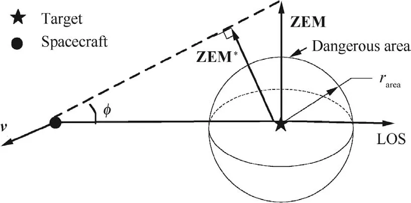
Fig.4 Dangerous area.

Fig.5 Condition with collision risk.
3.Design of BPNG
Usually,3D guidance law is realized by constructing two 2D guidance laws in two mutually vertical planes.As shown in Fig.3,the guidance goal of rendezvousing at the desired position can be equivalently described as making ZEM and ZEMbiashave the same components alongys-axis andzs-axis.And these can be achieved by applying proper guidance laws in thexso1ysplane andxso1zsplane,respectively.However,under the joint control-effort on two mutually vertical planes,the magnitude of ZEM cannot be guaranteed to be always larger thanrareaand ZEM may cross the dangerous area,as shown in Fig.5.Therefore,there is a drawback of safety for this guidance scheme.To overcome the demerit mentioned above,we investigate a new scheme of guidance law in the LOS rotation coordinate system.
3.1.Analysis of ZEM
The de finition of LOS rotation coordinate system25(er,eθ,eω)with respect to the LOS coordinate system is shown in Fig.6,wherein eris the unit vector of LOS and eωthe unit vector of the LOS angular velocity ωs.eθis de fined by eθ=eω× er.Known from Eq.(2)and the de finition of LOS rotation coordinate system,ZEM is parallel to eθ.And (er,eθ,eω)can be obtained by rotatingo1xsyszsalongxs-axis with Euler angle γ.Known from Fig.6,it is easy to find that ZEM and ZEMbiashave the magnitude difference ZEM-ZEMbiasand direction difference γ- γbias,and the guidance goal is to eliminate the two differences.
In Refs.23–26,3D relative dynamic equations in the LOS rotation coordinate system are presented as follows.


Fig.6 De finition of LOS rotation coordinate system.
where the subscripts m and t denote the corresponding parameters of spacecraft and target,and the subscriptsr,θ and ω the components of the corresponding parameters along the three coordinate axes of LOS rotation coordinate system;ais the acceleration,Δgthe gravity difference between spacecraft and target,and Ω the rotation rate of IPRL,which is the plane spanned by erand eθ.
According to Ref.23,the rotation rate of LOS rotation coordinatedsystemwithrespecttotheinitialcoordinatesystemωLRCcan be expressed in LOS rotation coordinate system as

And known from the rotation relationship between LOS rotation coordinate system and LOS coordinate system,ωLRCcan also be written as Eq.(5)


Substituting Eqs.(4)and(6)into Eq.(5),after some algebraic calculations,we have

During the close approach phase,the initial LOS is regarded as thex-axis of inertial coordinate system,which results in a small εsduring the whole close approach phase except the blind area.Therefore,it is acceptable to make the following approximation.

During the approach phase,we assume the target does not maneuver,i.e.,at,r=0 m/s2,at,θ=0 m/s2andat,ω=0 m/s2;the gravity difference Δgis usually very small,and hence its effect on the relative motion can be neglected;ωsis usually in the order of 10-3rad/s,therefore its quadratic term can also be ignored.Under the above assumptions,Eq.(3)can be simpli fied as

From Eq.(9),we can see that the change rates ofrand ωsare determined by the first two equations of Eq.(9),while γ is only determined by the third one of Eq.(9).In this way,rand ωsare decoupled from γ.Combining with Eq.(2),it is easy to find that the magnitude of ZEM is determined byrand ωswhile the direction of ZEM is determined by γ.Therefore,according to Eq.(9),we can design a guidance law,which decouples the magnitude control of ZEM from its direction control.
3.2.Design of BPNG
The traditional guidance laws usually regard zero miss distance as the primary guidance goal.However,for the special rendezvous with special relative range and orientation,the guidance goal is to make the magnitude and direction of ZEM approach special desired values.Correspondingly,according to Eq.(2),the magnitude and direction of desired ωsare time-varying and the change rule is not intuitive.So it is dif ficult to design guidance goal using LOS angles and LOS rates directly.
To overcome this dif ficulty,we design the guidance law based on ZEM due to its two advantages.Firstly,as stated in Section 2,ZEM represents the rendezvous position under zero control-effort,while ZEMbiasrepresents the expected rendezvous position and is constant variable during the close approach phase.Therefore it is convenient to design guidance law according to the relationship between ZEM and ZEMbias.Secondly,itiseasy to maketransformation between ZEM and ωsaccording to Eq.(2),so the guidance law designed using ZEM can be rewritten in terms of LOS angles and LOS rates,which can be estimated by the seeker and filter.The detailed design of guidance law based on ZEM is as follows.
Known from Refs.17,18,the commanded acceleration amfor 3D true proportional navigation guidance(TPNG)can be expressed as

whereNis the navigation ratio and usuallyN>2.
Note that

Substituting Eq.(11)into Eq.(10),amcould be expressed as a function of ZEM.

From Eq.(12),the directions of amand ZEM are identical with each other,and the magnitude of amis proportional to that of ZEM.TPNG can also be rewritten in the following equivalent form.

which means the expected ZEMbiasis zero.Correspondingly,if the ZEMbiasis not zero,the commanded acceleration becomes

Essentially,Eq.(14)can be rewritten in such form.

whereKdenotes the proportional gain.
From Eq.(15),the componentam,ris zero,which results from the fact that both ZEM and ZEMbiasare vertical to er.Therefore,combining with Eq.(9),the magnitude of ZEM is only determined byam,θwhile the direction is determined byam,ω.And according to Eq.(15),am,θandam,ωcan be designed to be proportional to the magnitude difference and direction difference between ZEM and ZEMbias,respectively.

whereKZEMandKγdenote the corresponding proportional gains;ZEMbiasand γbiasrepresent the magnitude and direction of ZEMbias,and they could be determined by the expected rendezvous range and orientation directly,as shown in Fig.3.In order to make ZEM approach ZEMbiasin finite time and for the sake of simplicity,KZEMandKγare set to be

Substituting Eq.(17)into Eq.(16)and rewriting it in terms of ωs,which can be obtained by the seeker and filter,the following expression could be obtained.

Eq.(18)is the acceleration command of BPNG designed in this paper,wherein ZEMbias˙r/r2and γbiasare the corresponding bias terms,and γ can be calculated according to the second equation of Eq.(7).
Substituting Eq.(18)into Eq.(9),we deduce the following relative dynamic equations under the control of BPNG

where ωs0,r0and γ0denote the initial values of ωs,rand γ.
From the first equation in Eq.(20),LOS rate ωswill increase monotonously and tend to be in finite with the decrease ofrwhenN>2.In case the guidance system works abnormally,the guidance system will stop working when the spacecraft enters the blind area,where ωsreaches immeasurable value.From the second expression of Eq.(20),the angle γ approaches γbiaswith the decrease ofrwhenN>0,which means the direction of ZEM will approach that of ZEMbiasmonotonously.
Substituting the closed-form solution of ωsinto Eq.(2),we have the closed-form solution of ZEM.

which indicates that the magnitude of ZEM will monotonously approach that of ZEMbiasfrom its initial value ZEM0with the decrease ofr,whenN>0.
Substituting the first equation of Eq.(20)into the first equation of Eq.(18),we have the closed-form solution of commanded accelerationam,θwith respect tor.

from which we can see thatam,θwill be bounded in an acceptable range,ifN≥2.
Therefore,according to the above analyses,as long asN≥2,the designed biased guidance law can successfully make ZEM approach ZEMbias.
3.3.Analysis of collision risk
According to the de finition of the dangerous area,in order to avoid the potential collision threat,ZEM must always be controlled outside the dangerous area.In other words,i.e.,ZEM>rareaduring the whole approach phase.
From Eq.(21),the following conclusions can be drawn:
(1)In the case of ZEM0>ZEMbias>rareaor ZEMbias>ZEM0>rarea,ZEM approachesZEMbiasmonotonically and is always larger than rarea.The target will not form potential collision risk to spacecraft during the whole approach phase.
(2)In the case of ZEMbias>rarea>ZEM0,the target poses potential collision risk to spacecraft at the beginning,but ZEM will increase to be larger than rareaeventually under the control of BPNG.Therefore,the collision risk will be rapidly and greatly degraded after the beginning and be eliminated finally.
4.Optimization of BPNG
During the approach phase,we not only aim to guide the spacecraft to the desired position without collision risk,but also expect the guidance law to be ef ficient and consumes as less fuel as possible.For the convenience of optimization,the relative dynamic equations are rewritten in terms of magnitude and direction of ZEM firstly,and then the OBPNG law is derived by solving the Schwartz inequality.27
4.1.Transformation of relative dynamic equations
From the above analysis,the 3D relative dynamic equations corresponding to BPNG in the LOS rotation coordinate system can be simpli fied as Eq.(23).

Substituting Eqs.(24)and(25)into Eq.(23),the simpli fied relative dynamic equation set,which is in terms of magnitude and direction of ZEM,could be obtained as

From Eq.(26),it is clear that the first equation determines the change of ZEM and the second equation determines the change of γ.Compared with Eq.(23),Eq.(26)is simpler and its physical meaning is more intuitive.
4.2.Optimal BPNG
According to Eq.(26),the change of ZEM is determined byam,θ,while the change of γ is affected not only byam,ω,but also by ZEM.Therefore,we can optimize BPNG by using a twostep optimization strategy.The first step is to obtain the optimal control inputam,θand then the second step is to obtain the optimal control inputam,ω.
From the first equation of Eq.(26),ZEM at the rendezvous momenttfis
The expected value of ZEM(tf)is ZEMbiasand hence the preceding equation can be rewritten as follows:

Applying the Schwartz inequality to Eq.(28),the following expression could be deduced.

Apparently,Eq.(29)could be rewritten in terms of acceleration command.

It is obvious that the integral of the square of the commanded acceleration will be minimized when the equality sign holds.From the characteristic of the Schwartz inequality,the equality sigh holds when

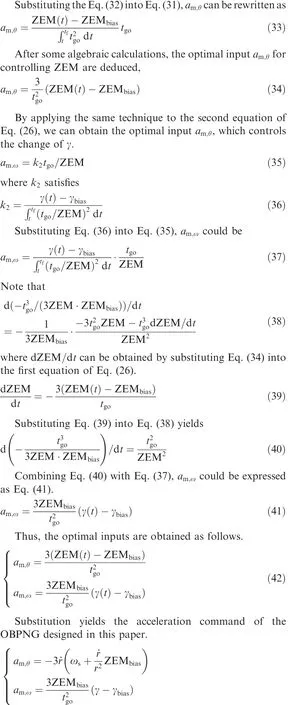
wherek1satis fies

5.Simulation results
In order to verify the validity of the designed guidance laws,we construct two simulation scenarios.Table 1 shows the corresponding initial states of the spacecraft and target in the inertial coordinate system.The only difference between the twoscenarios is the velocity of spacecraft,which results in different initial zero effort miss vectors(ZEM0)and different conditions of collision risk.The proportional gainNis assumed to be 3.The radii of dangerous areas for both scenario 1 and scenario 2 are assumed to be 20 m,the expected ranges of rendezvous 21.2 m and the expected directions 45°.The range of blind area is selected as 100 m.

Table 1 Initial states for scenarios 1 and 2.
From the initial states of spacecraft and target,the initial values of φ for scenarios 1 and 2 are 8.1°and 0.5°,respectively.And according to the ranges of blind area and expected rendezvous position,the ultimate values of φ could be estimated to be 11.9°.Therefore,it is acceptable to ignore the difference between ZEM and ZEM*.
For the purpose of comparison,a biased proportional navigation guidance law,which represents the guidance scheme that 3D guidance goal is achieved by constructing two 2D guidance laws in two mutually vertical planes,is obtained by projecting Eq.(14)into the LOS coordinate system,i.e.,

where the subscriptsysandzsrepresent components of variables along theys-axis andzs-axis of the LOS coordinate system,as shown in Fig.3.Rewriting Eq.(44)in terms of ωzsand ωys,which represent the components of ωsalong theys-axis andzs-axis,the following equations are obtained.


Fig.7 Projections of ZEM for scenario 1.
For simplicity the above guidance law is denoted by BPNG-LOS,andNis assumed to be 3.
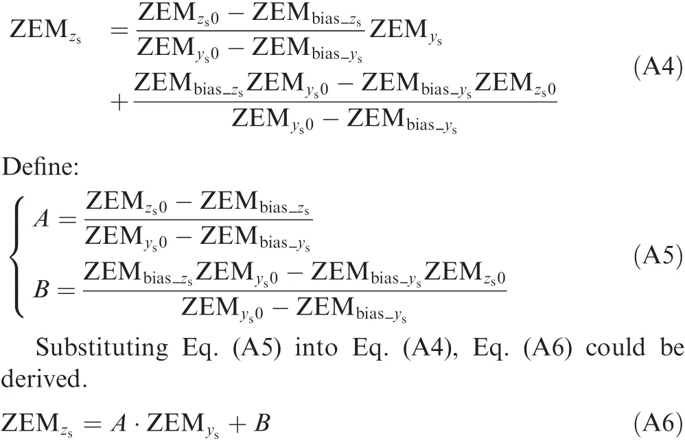
With the control effort of BPNG-LOS,ZEM has the following characteristic.(The detailed derivation is provided in the Appendix A)

whereAandBare constant variables in terms of the components of ZEM0and ZEMbiasalongys-axis andzs-axis.
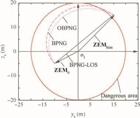
Fig.8 Terminal projections of ZEM for scenario 2.

Fig.9 Magnitude changes of ZEM for scenarios 1 and 2.
From the above expression,ZEMzsand ZEMysare in a linear relation,which is independent of the proportional gainNand only determined by ZEM0and ZEMbias.The terminal projection of ZEM is a line segment with the starting point of ZEM0and endpoint of ZEMbiaswith the control effort of BPNG-LOS during the close approach phase,as shown in Fig.5.Therefore,BPNG-LOS will form different potential collision risks depending on the positions of ZEM0and ZEMbiasrelative to the dangerous area.
Fig.7 shows the projections of ZEM on theyso1zsplane for scenario 1,wherein the magnitude of ZEM0is larger than the radius of the dangerous area and there exists no collision risk at the beginning of the close approach phase.Known from the changetrendsoftheterminalprojections,i.e.,ZEM approaches ZEMbiasgradually,all the three guidance laws can guide the spacecraft to the desired position.However,from the perspective of safety,ZEM corresponding to BPNG-LOS crosses the dangerous area,which has potential collision risk to the spacecraft,while ZEM s of BPNG and OBPNG evade the dangerous area,which mean both of them satisfy the safety constraint.
Fig.8 shows the terminal projections of ZEM for scenario 2,wherein the magnitude of ZEM0is smaller than the radius of the dangerous area,which forms collision risk at the beginning of the close approach phase.Under this circumstance,although all the three guidance laws can make ZEM approach ZEMbias,the magnitudes of ZEMs corresponding to BPNG and OBPNG increase monotonously,which means the collision risk is degraded,while that corresponding to BPNGLOS decreases at the beginning,which means the collision risk is upgraded.

Fig.10 Direction changes of ZEM for scenarios 1 and 2.
Fig.9 shows the magnitude changes of ZEM with respect to time in the two scenarios.Simulation results indicate that the magnitudes for BPNG and OBPNG have the same change trends,which seems to violate the results of Figs.8 and 9(b).Known from Eqs.(18)and(43),when the proportional gainNof BPNG is 3,the commanded accelerations of controlling magnitude are the same while those of controlling direction are different,which results in the fact that the ZEMs of BPNG and OBPNG are different but have the same magnitudes.Simulation results in Fig.9 also indicate that the magnitudes for BPNG and OBPNG approach the expected value ZEMbiasmonotonically,which leads to the evasion of the collision risk for scenario 1 and the relief of collision risk for scenario 2.While the magnitude corresponding to BPNG-LOS decreases firstly and then increases,which causes ZEM to cross the dangerous area and the collision risk to deteriorate.
Fig.10 shows the direction changes of ZEM with respect to time.We can see the directions approach to the expected value γbiasgradually under the control of BPNG and OBPNG,while the direction corresponding to BPNG-LOS approaches γbiasquickly during a short time,which corresponds to the time when the magnitude of ZEM is around its minimum.
Fig.11 shows the velocity increments for scenarios 1 and 2.By comparing the simulation results,we can find the velocity increment needed corresponding to BPNG-LOS is the smallest,and the velocity increment needed corresponding to OBPNG is obviously smaller than that of BPNG,which indicates the ef ficiency of optimization.

Fig.11 Velocity increments for scenarios 1 and 2.
Above all,the three kinds of biased guidance laws are all able to guide the spacecraft to the descried position.However,BPNG-LOS does not meet the safety requirement,while both BPNG and OBPNG have the characteristic of evading the dangerous area.And OBPNG is superior to BPNG due to its less energy consumption.
6.Conclusions
(1)For the purpose of guiding the spacecraft to rendezvous with targetinthe desired range anddirection withoutcollisionrisk,thispaperproposesanovelBPNGfortheclose approach phase.By analyzing the characteristic of ZEM in the LOS coordinate system,we obtain the conclusion that it is feasible to decouple the range control and direction control of ZEM.The corresponding BPNG is designed based on the traditional TPNG.Theoretical analysis proves that the designed BPNG ful fills the expectedguidancegoalquitewell.Takingthecontrolef ficiencyintoaccount,theOBPNGisconstructedbysolving Schwartz inequality.Simulation results verify that both BPNG and OBPNG can guide the spacecraft to the desired rendezvous position with the ability of evading the dangerous area,and OBPNG consumes less fuel.
(2)The proposed guidance laws are designed with the assumptions that the target does not maneuver and all the guidance information needed can be measured accurately.In the future,the effect of target maneuver and measurement errors on the performance of the guidance laws may need to be discussed deeply,and corresponding improvement methods may also need to be explored.
Acknowledgements
This study was co-supported by the National Natural Science Foundation of China(No.11372345)and the National Basic Research Program of China(No.2013CB733100).
Appendix A
Under the assumptions that the quadratic terms of LOS rates can be ignored and the target does not maneuver,the 3D relative dynamic equations in the LOS coordinate system could be expressed as follows.25

where ωysand ωzsare the components of ωsalongys-axis andzs-axis.
Substituting Eq.(45)into the preceding equations and after some algebraic calculations,the closed-form solutions of ωysand ωzsare obtained.

where ωys0and ωzs0denote the initial values of ωysand ωzs.
Substituting Eq.(A2)into Eq.(2),the closed-form solution of ZEMyand ZEMzare achieved.

In order to eliminate (r/r0)N,substituting the first equation of Eq.(A3)into the second equation of Eq.(A3)yields
1.Murtaugh SA,Criel HE.Fundamentals of proportional navigation.IEEE Spectr1966;3:75–85.
2.Guelman M.A qualitative study of proportional navigation.IEEE Trans Aerosp Electron Syst1971;7(4):637–43.
3.Guelman M.Proportional navigation with a maneuvering target.IEEE Trans Aerosp Electron Syst1972;AES-8(3):364–71.
4.Bischof B,Kerstein L,Starke J,Guenther H,Forth WP.Robotic geostationary orbit restorer(ROGER).Proceedings of the 54th international astronautical congress of the international astronautical federation;2003 Sep 29-Oct 3;Bremen,Germany.Paris:International Academy of Astronautics,and International Institute of Space Law;2003.
5.Williams P.In-plan payload capture with an elastic tether.J Guid Control Dyn2006;29(4):810–22.
6.Zhai G,Qiu Y,Liang B,Li C.On orbit capture with flexible tether–net system.Acta Astronaut2009;65(5–6):613–23.
7.Brainin SM,Mcghee RB.Optimal biased proportional navigation.IEEE Trans Autom Control1968;13(4):440–2.
8.Shukla U,Mahapatra PR.Optimization of biased proportional navigation.IEEE Trans Aerosp Electron Syst1989;AES-25(1):73–81.
9.Yuan PJ,Chern JS.Analytic study of biased proportional navigation.J Guid Control Dyn1992;15(1):185–90.
10.Kim BS,Lee JG,Han HS.Biased PNG law for impact with angular constraint.IEEE Trans Aerosp Electron Syst1998;34(1):277–88.
11.Jeong SK,Cho SJ,Kim EG.Angle constraint biased PNG.Proceedings of the 5th Asian control conference;2004 Jul 20-23;Melbourne,Victoria,Australia.Piscataway,NJ:IEEE Press;2004.p.1849–54.
12.Akhil G,Ghose D.Biased PN based impact angle constrained guidance using a nonlinear engagement model.Proceedings of 2012 American control conference;2012 Jun 27–29;Montreal,QC.Piscataway,NJ:IEEE Press;2012.p.950–5.
13.Erer KS,Merttopc¸uog˘lu O.Indirect impact-angle-control against stationary targets using biased pure proportional navigation.J Guid Control Dyn2012;35(2):700–3.
14.Kim TH,Park BG,Tahk MJ.Bias-shaping method for biased proportional navigation with terminal-angle constraint.J Guid Control Dyn2013;36(6):1810–5.
15.Zhang YA,Ma GX,Liu AL.Guidance law with impact time and impact angle constraints.Chin J Aeronaut2013;26(4):960–6.
16.Yang CD,Yang CC.Analytical solution of three-dimensional realistic true proportional navigation.J Guid Control Dyn1996;19(3):569–77.
17.Yang CD,Yang CC.Analytical solution of generalized threedimensional proportional navigation.J Guid Control Dyn1996;19(3):721–4.
18.Yang CD,Yang CC.Analytical solution of 3D true proportional navigation.IEEE Trans Aerosp Electron Syst1996;32(4):1509–22.
19.Tyan F.The capture region of a general 3D TPN guidance law for missile and target with limited maneuverability.Proceedings of the 2001 American control conference;2001;Arlington,VA.Piscataway,NJ:IEEE Press;2001.p.512–17.
20.Tyan F.Uni fied approach to missile guidance laws:A 3D extension.IEEE Trans Aerosp Electron Syst2005;41(4):1178–99.
21.Tyan F.Capture region of a GIPN guidance law for missile and target with bounded maneuverability.IEEE Trans Aerosp Electron Syst2011;47(1):201–13.
22.Yang CD,Yang CC.A uni fied approach to proportional navigation.IEEE Trans Aerosp Electron Syst1997;32(2):557–67.
23.Li KB,Chen L,Bai XZ.Differential geometric modeling of guidance problem for interceptors.Sci China Technol Sci2011;54(9):2283–95.
24.Li KB,Chen L,Tang GJ.Improved differential geometric guidance commands for endoatmospheric interception of highspeed targets.Sci China Technol Sci2013;56(2):518–28.
25.Li KB,Zhang TT,Chen L.Ideal proportional navigation for exoatmospheric interception.Chin J Aeronaut2013;26(4):976–85.
26.Li KB,Chen L,Tang GJ.Algebraic solution of differential geometric guidance command and time delay control.Sci China Technol Sci2015;58(3):565–73.
27.Zarchan P.Tacticalandstrategicmissileguidance. 4th ed.Reston:AIAA Inc.;2002.p.149–55.
 CHINESE JOURNAL OF AERONAUTICS2016年1期
- CHINESE JOURNAL OF AERONAUTICS的其它文章
- Plastic wrinkling prediction in thin-walled part forming process:A review
- Progress of continuously rotating detonation engines
- Microstructure control techniques in primary hot working of titanium alloy bars:A review
- A hybrid original approach for prediction of the aerodynamic coefficients of an ATR-42 scaled wing model
- Dynamic modeling and analysis of vortex filament motion using a novel curve- fitting method
- Boundary-layer transition prediction using a simpli fied correlation-based model
