Gust response analysis and wind tunnel test for a high-aspect ratio wing
Liu Yi,Xie Chngchun,*,Yng Cho,Cheng Jilin
aSchool of Aeronautic Science and Engineering,Beihang University,Beijing 100083,ChinabChengdu Aircraft Industrial(Group)Co.Ltd.,Chengdu 610073,China
1.Introduction
High-altitude long-endurance unmanned aerialvehicles(HALE UAVs)are always equipped with light wings of high aspect ratio.These long and slender wings,by their inherent nature,can maximize lift-to-drag ratio and endurance.Onthe other hand,they may undergo large deformations during normal operating loads.Geometric nonlinearity becomes a very important factor that affects aeroelastic stability and response.Thus,linear theories are not relevant for their analysis,1,2and nonlinear features must be consistently considered in both the structural and aerodynamic models of the numerical analysis.This leads to the conclusion that the coupled effects between these large de flection and vehicle flexibility and flight dynamics as well as other aeroelastic effects(e.g.,gust response, flutter instability)must be properly accounted for in a nonlinear aeroelastic framework.3
Gust response analysis is a serious problem for aircraft especially for very flexible aircraft whose large deformation may signi ficantly change structural dynamic characteristics and aerodynamic features.Many researchers have addressed particular issues on gust response analysis.Su and Cesnik studied the dynamic response of a highly flexible flying wing4under a spatially-distributed discrete gust model in the time domain by a low-order,nonlinear,strain-based finite element framework.Dong et al.5studied the nonlinear gust response of free flexible aircraft using a CFD/CSD method.Considering the big time consumption of the CFD/CSD method and the limitation of nonlinear beam for a simple structural model,this paper presents a theoretical analysis method for aerodynamic and gust response estimation of flexible high-aspect ratio wings,which may help to illustrate the geometrically nonlinear gust response phenomena and characteristics of large-aspect ratio wings.Structural dynamic computation based on a nonlinear finite element method is combined with nonplanar unsteady vortex lattice aerodynamic computation marched in the time domain to describe the real physical response to a flexible wing under gust load.This fully nonlinear method can be applied to structure/aerodynamic coupling problems beyond the limitation of structural model complexity,so it is convenient to be applied in engineering analysis.
Although the theoretical analysis has discovered some nonlinear features of very flexible wings,it is still necessary to conduct a series of experiments to observe and understand the nonlinear phenomena and physical mechanics more intuitively and to validate the theoretical results for large-aspect ratio wings.Geometric nonlinearity makes distinguished difference for very flexible wings compared with traditional aeroelastic experiments.The test model,suspension system,measuring equipment,and techniques all should concern about the object’s nonlinear features and by all means present them as original and measurable.Because of the complex technical and operating obstacles,gust wind tunnel tests seldom appear,especially for flexible structures,which reveals its increasing importance.This paper introduces a recently conducted wind tunnel test of nonlinear flutter and gust response for a large deformed wing(requiring at least 25%de flection compared with the span length)to validate theoretical analysis.Nonplanar unsteady aerodynamic combined with nonlinear structural dynamic analysis in the time domain,which is strongly recommended after Helios mishap,6is used for flexible structural responses problems.Some novel experimental techniques for very flexible wing tests are also introduced brie fly.
2.Theory
2.1.Structure geometric nonlinearity
Geometric nonlinearities are based on the kinematic description of the body and the strain on the wing should be de fined in terms of local displacement of the wing for dynamic motions.7These result in the nonlinear geometric equations including the quadric term of the displacement differential,and the nonlinear force equilibrium equation established on the deformed state of the structure.Geometric nonlinear effects are prominent in two different aspects:(A)geometric stiffening due to initial displacements and stresses,and(B)follower forces due to a change in loads as a function of displacements.8Both of these two factors are considered in this paper and solved with the nonlinear incremental finite element method,9which has been maturely developed,and two formulas called total Lagrange formulation(TLF)and updated Lagrange formulation(ULF)10are well known.The ULF is used in the current work and the main equations are presented below.
The relationship between the nonlinear Lagrange/Green strain and the displacement is

wheretui,jmeans the partial derivative of displacement componentuito the coordinatexjat timet.
Despite the large elastic deformation,the material is thought to be within the elastic limitation for the little strain.The conjugate Kirchhoff stress tensorSjiat timetsatis fies

wheretnjis direction cosine of small area element dsat timet,and dTjis the corresponding surface force in which the follower force effect is considered.The linear elastic constitutive relation is given as follows

whereDijklis the elastic tensor,which has a different form for an isotropic or anisotropic material.
By using the finite element method(FEM)to discrete the structure,the element equation for static problems is given as11

Considering the structural damping effect,the equation of the dynamic problem can be expressed as

whereMt+Δtis the instant system mass matrix at timet+ Δt,Bis the structural damping matrix,tKis the structural stiffness matrix including the linear part and nonlinear part,u(t)is the structural displacement vectorp(t)is the instant outer force in transient analysis.
In a direct transient response,a structural response is computed by solving a set of coupled equations using direct numerical integration.The fundamental structural response(displacement)is solved at discrete times,typically with a fixed integration time step Δt.By using a central finite difference representation for the velocity{(t)}and the acceleration{(t)}at a discrete time,

and averaging the applied force over three adjacent time points,the equation of motion can be rewritten as:

Collecting terms,the equation of motion can be rewritten as:

The detailed arithmetic and implement can be found in Ref.12
For aeroelastic stability problems such as flutter,an assumption of small-amplitude vibration around the nonlinear static equilibrium state is suitable for many dynamic problems,including dynamic stability.Ignore the structural damping effects,that is,

whereu is the large static de flect equilibrium deformation from Eq.(4)and x is a small vibration deformation.According to Eq.(5)and the static equilibrium condition,the vibration equation of the system under steady forces reduces to

where MTis the inertial matrix of the structure at the static equilibrium con figuration and KTis the corresponding stiffness matrix.Both of them are the nonlinear functions ofu and vary under different equilibrium states,which is the key feature of geometric nonlinear structures.From Eq.(10),the structural mode shapes and frequencies are deduced.Combined with nonlinear aerodynamic computation,the flutter boundary can be obtained by p-k or other classic methods.The flutter boundary is only a predicted one under a certain state.Different equilibrium states have different predicted flutter boundaries and the exact flutter boundary should be searched iteratively to make the flutter speed consistent with the static equilibrium flight speed.
2.2.Unsteady vortex lattice method
The unsteady vortex lattice method(UVLM),as a timedomain aerodynamic computation,is now widely used in unsteady aerodynamic calculation for micro air vehicles(MAVs), flapping wings,and many other aspects.Because of the simple programming effort it requires,the UVLM can be easily combined with structural dynamic computation to get response results for aeroelastic structures.Additionally,the exact boundary condition is satis fied on the actual wing surface,which can have camber and various platform shapes.Thus,it can be conveniently used for very flexible wings whose aerodynamic surfaces are subjected to large spatial deformations13.The UVLM is based on full potential equations without any linearization and can well re flect the unsteadiness effects of the 3-D low-speed flow around a flexible lifting surface.
Vortex ring elements are used to discrete the boundaries of the aerodynamic domain in the UVLM,for both the wing and the wake as in Fig.1.U(t),V(t),W(t)are the three components velocity of coming flow, Δbij,Δcij,nij,Γijrepresent the span length,chord length,normal vector and vortex strength ofijth lattice.Note that the leading segment of the vortex ring is placed on the panel’s quarter-chord line so that the collocation point is located at the center of the three-quarter chord line.The whole flow domain is represented by vortex rings and the aerodynamic in fluence coef ficient can be obtained via Biot–Savart law,for which a vortex ring is modeled by four straight vortex lines.Therefore,the integration along the ring can be rewritten in a summation way as in Eq.(12).
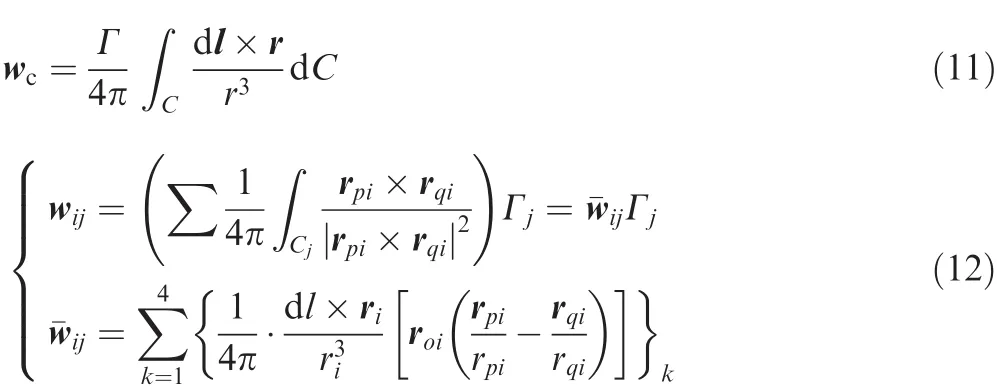
In each discrete time step computation,the wing is moved along its flight path and each trailing edge vortex panel sheds a wake panel with the vortex strength equal to its circulation in the previous time step;15thus the wake panels are formed.Since the vortex wake is force-free,each vortex must move with the local stream velocity.If the velocity induced by the bound vortex and the wake vortex is considered in the local stream velocity for the wake vortex,a free wake model is established and it can re flect the wake rollup effect as shown in Fig.2.This is signi ficant for flapping wings or multi-lifting surfaces,whose aerodynamic interferences play an important role in aerodynamic computation.For a single flexible wing considered in this paper,a fixed wake model is used(shown in Fig.3),in which the wake panels follow the motion of the trailing edge and move with the local flow velocity ignoring the in fluence of induced velocities on the wake by the bound vortex and the wake vortex.According to the comparison of these two models,the aerodynamic loads are well consistent with each other.For a gust response problem,gust load is the main factor that matters for structural response in an aerodynamic way,so the fixed model is good enough for the single flexible wing response problem and it brings tremendous computation ef ficiency compared with the free wake model.
Speci fic vortex distribution on the wing is determined by the geometric exact boundary condition,i.e.,

where Φ is the full potential function including the bound vortex and the wake vortex and v is the velocity of the local boundary movement.A detailed expression of the formula above can be written as15

where A is the normal aerodynamic in fluence coef ficient of the bound vortex,Γ is a vector consisting of the panel vortex circulation on the wing,V(t)=[U(t),V(t),W(t)]are the timedependent kinematic velocity components due to the motion of the wing or different kinds of unsteady coming flow including the gust excitation discussed in this paper,Vw=[uw,vw,ww]are the velocity components induced by the wake vortices,and n is the local normal vector of the bound vortex.Since the locations of all vortex points are known,these terms are known at each time step and can be transferred to the right-hand side of the equation.Consequently,the right-hand side(RHS)is de fined as15
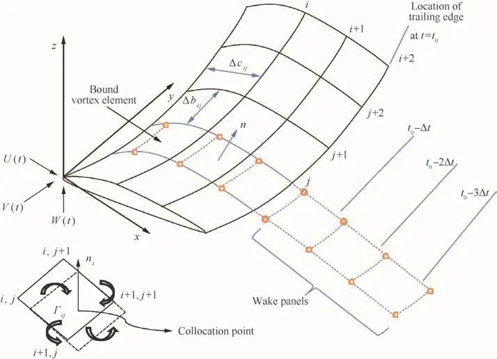
Fig.1 Nonplanar unsteady vortex lattice method model.

Fig.2 Free wake model.

Fig.3 Fixed wake model.

Once the computations of the in fluence coef ficients and the right-hand side vector are completed,the zero normal boundary condition at all the wing’s collocation points will result in a set of algebraic equations for each collocation pointKas

Solving the equations above,the circulation of the bound vortex can be obtained.For the pressure distribution calculations,the local circulation is needed,which is equal to Γijfor the leading edge panel but the difference Γij- Γi-1,jfor all the elements behind it.The fluid dynamic loads can be computed by using the Bernoulli equation and the pressure difference is given as15

whereplandpuare the pressure of the low and up aerosurface,is the corresponding tangential velocity of coming flow.
The resultant pressure difference expressed by the bound vortex is15

where Δcijand Δbijare the panel lengths in theith andjth directions,respectively.Similarly, τiand τjare the panel tangential vectors in theith andjth directions,respectively.
The contribution of this panel to the loads is then

Although the UVLM is deduced under unsteady cases,it can also be implemented in steady cases if only setting the coming flow to be steady and keeping the wing stable.
2.3.Stability and gust response analysis
Before the gust response analysis,it is necessary to investigate the static aeroelastic and dynamic stability characteristics.Since real aircraft and the tested wing in this paper are under steady aerodynamics before the gust encounters,for a very flexible wing,it may cause large static structural deformation and change aerodynamic loads and structural dynamic features.All these may have big in fluences on gust response results.In this paper,iterative computation is used to solve the static aeroelastic problem via a nonplanar vortex lattice method under steady cases coupled with nonlinear static structural analysis.The surface spline is responsible for the information exchanges between the structure and aerodynamics,and thus the lifting surface can be updated according to real structural deformations automatically in each computation.Iterative process and nonplanar aerodynamic computation together could well predict the nonlinear static deformation and aerodynamic load distribution.Upon the nonlinear static equilibrium state,quasi-mode analysis is conducted which can consider the nonlinear stiffness and stress effects caused by structural geometric nonlinearity.Combined with the nonplanar doublet-lattice method,it can give out a predicted flutter boundary under a certain nonlinear equilibrium state.That may not be the exact flutter speed but can re flect some dynamic aeroelastic characteristic,which is a valuable reference for gust response analysis and test.The analysis flow chart is expressed in Fig.4.
Gust response analysis is implemented in the discrete time domain.At the beginning of each time step computation,the unsteady aerodynamic load is computed,which,along with other loads such as gravity,acts as an outer force in nonlinear structural dynamic analysis.The structural displacement and velocity at the end of last computation step will be treated as the initial condition in the next structural transient dynamic analysis,which can guarantee the continuity of structural response analysis.Each structural transient dynamic analysis is carried forward for a time step,during which the unsteady load is kept unchanged.This will make sense if the time step is small and the load treated constant is reasonable.The resultant structural displacement and velocity are used to update the aerodynamic surfaces and exact geometric boundary conditions for next step unsteady aerodynamic computation.Although the computation is implemented in the discrete time domain,the structural displacement and velocity are continuous and the updated aerodynamic computation helps the unsteady aerodynamic computation accurate and practical.The legible analysis procedure is shown in Fig.5.
3.Experimental wing model and root suspension system
3.1.Model description

Fig.4 Nonlinear aeroelastic stability analysis flow chart.
A series of careful analysis computations has been performed to design a reasonable model,which might induce large deformation and notable geometrically nonlinear characteristics within the wind tunnel working range.Because of the request of consistency with the prototype wing that was originally designed in a traditional linear way,the tested wing may not be a typical very flexible wing,but the large aspect ratio and large deformation were guaranteed,and the experimental techniques and the analysis methods discussed in this paper can still be universally used for other very flexible wings.A cross-section single aluminous beam was selected to provide the main bend and twist stiffness.A wood rib shaped as the designed airfoil and plastic heat shrinkage film were used to maintain the wing shape.The wing surface was cut into sections and each section was attached to the beam at a single point.1 mm space between adjacent sections was for eliminating the additional stiffness effect since the theoretical structural dynamic analysis only concerned about the beam effect.Detailed information about the wing is shown in Table 1.The 3-D CATIA model,the beam finite element model used for theoretical analysis,and the final accomplished test model are shown in Fig.6.

Fig.5 Time-domain nonlinear aeroelastic response analysis flow chart.

Fig.6 Test wing model.
3.2.Suspension system
A suspension system for the wind tunnel test is shown in Fig.7.This suspension system was fixed on both the floor and ceiling of the wind tunnel,and a lot of batter braces and a steel tension rope as well as a roof bar staying on the side wall were used to guarantee the suspension stiffness since a geometrically nonlinear aeroelastic response was sensitive to structural dynamic changes and a potentially weak suspension may cause signi ficant problems to make test results inconsistent with analysis results.
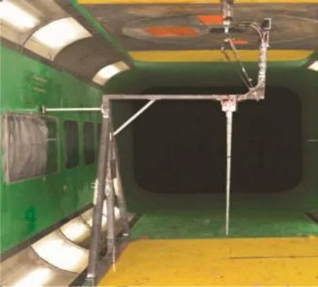
Fig.7 Wing suspension system.

Table 1 Design parameters wing model.
3.3.Measuring techniques
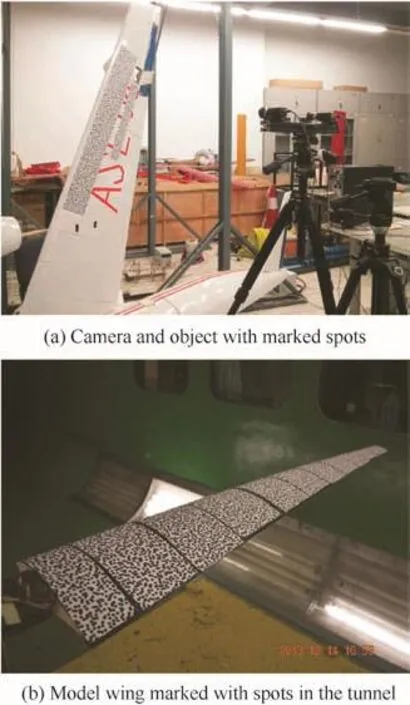
Fig.8 3-D camera measurement analysis system.
For the very flexible wing,the spatially distributed large deformation is dif ficult to measure since the traditional means are only suitable for 2-D de flection cases.In the wind tunnel test,the measuring equipment cannot touch the objects and even cannot be placed in the tunnel.A 3-D camera measurement analysis system(in Fig.8),one of the non-contact measurement techniques,is novelly adopted to overcome this problem.The system consists of three parts:an object to be tested;an analysis computer;a camera with two lenses that imitate human’s eyes to grasp 3-D displacements and can eliminate vibration disturbance of the environment.Before measuring,the interested area should be marked with random spots,which are used to adjust the camera and the computer.During measuring,the camera captures the de flections and velocities of the marked spots and saves the current image as pictures at every appointed interval.Then the computer can use these pictures to recover the time-dependent structural deformation and velocity.This deformation measurement is meaningful for the very flexible wing experiment.Pictures in Fig.8 show the 3-D camera measurement analysis system and the tested wing in the tunnel.
Due to strong aeroelastic coupling,the very flexible wing’s large deformation may signi ficantly change the aerodynamic loads,which are quite different from linear computation,16so the load measurement is also very important.In this experiment,a 6-component aerodynamic balance was set at the wing root and strain gages were also used to surveil the root load.Two accelerometers were set at the 2/3 span locations horizontally and vertically to get the structural response since previous research17has shown that the horizontal mode has notable in fluence on nonlinear flutter for very flexible wings.
3.4.Gust generator
In this experiment,a gust generator was installed upstream in the tunnel as shown in Fig.9.It consists of two symmetric oscillating wings driven by a linear motor to generate alterable amplitude and frequency continuous sin gust.More detailed design method and working principle are in Refs.18,19.

Fig.9 Gust generator.
4.Theoretical and experimental results
4.1.Flutter theoretical analysis results
Before the experiment,linear and geometrically nonlinear aeroelastic stability analyses were implemented.The linear analysis used the planar vortex lattice method(VLM)and the planar double-lattice method(ULM)that could be easily solved in MSC.NASTRAN.The nonlinear analysis used self-programmed nonplanar VLM20and nonplanar DLM that could accomplish the spatial curved lifting surface’s aerodynamic computation and structural geometric nonlinearity.
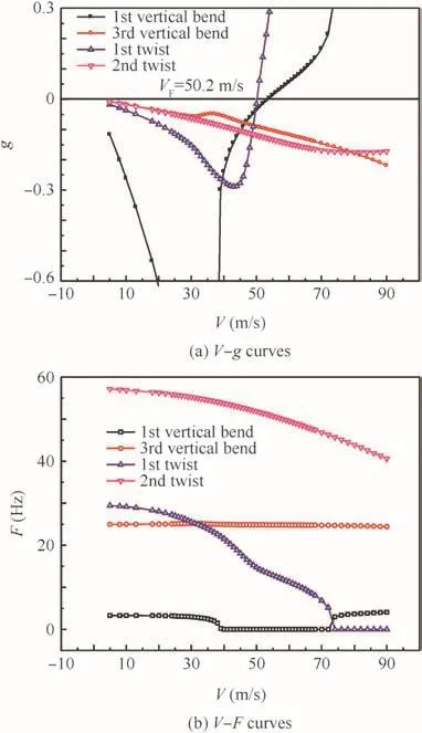
Fig.10 Linear flutter analysis results.

Fig.11 Nonlinear flutter analysis results.
The linear flutter speed is irrespective with load and structural deformation.TheV–gandV–Fcurves in Fig.10 indicate that it is a typical bend/twist coupling flutter and the critical flutter speed is 50.2 m/s.In geometrically nonlinear analysis,structural dynamics characteristics vary with different loads and de flections.The nonlinear flutter curves in Fig.11 demonstrate that the coupling mode changed to vertical bend vs horizontal bend and the critical nonlinear flutter speedVFdecreased to 47.5 m/s.The comparison between the two theoretical analyses illustrates that the geometric nonlinearity of an aeroelastic system narrows an aircraft’s flight envelope and the horizontal bending mode may become signi ficant in nonlinear lf utter.
4.2.Experimental flutter and analysis results
The large spatially distributed deformation of the very flexible wing was tested in the wind tunnel.The wing was suspended vertically under a 5°angle of attack.Wing tip de flections under different wind speed cases obtained from 3-D camera measurement are shown in Fig.12.The vertical de flections tended to converge when the speed was high.Note that the spanwise de flections are comparable with the vertical de flations,which cannot be re flected in the linear analysis let alone the chordwise de flections since the lifting surface is imbedded in a 2-D plane and the aerodynamic force only acts in the vertical direction under linear cases.The wing tip de flections comparison between the test and analysis results is also presented in Fig.12.Both of these two results can demonstrate the large deformations of the flexible wing and are very consistent except for the spanwise de flections when the speed is high.This may be caused by the error of the 3-D camera in the spanwise direction since it is sensitive in the vertical de flections and the spanwise de flections are a little away from its marked range.The deformation of the wing along the span in a certain state(48 m/s,5°angle of attack)recovered by the non-contact camera measurement is presented in Fig.13 and some actual deformed structural photos under different coming flow velocityVare shown in Fig.14.Both the tested data and actual photos present the large de flection of the wing tip(almost 50%deformation in the vertical direction),especially the large spanwise deformation,which is usually ignored in linear analysis.
Table 2 shows the original mode frequency obtained by a ground vibration test.In order to get structural dynamic response information, the time-domain accelerometers response signals are transformed into the frequency domain,as shown in Fig.15.The theoretical nonlinear analysis has revealed that as speed increasing,horizontal modes become unstable and participate in nonlinear flutter.This conclusion can be validated from Fig.15 in some aspects.When the speed is 20 m/s,the structural deformation is small and the frequency distribution,shown in Fig.15(a),is similar to the original value in Table 2.As the speed increases to 40 m/s as shown in Fig.15(b),the 2nd horizontal bending mode comes forth on the curve,and simultaneously three modes peaks between 25–35 Hz tend to be blurry.When the speed turns to 45 m/s in Fig.15(c),the 2nd horizontal bending mode becomes evident.When extremely approaching the flutter speed(48.5 m/s)as shown in Fig.15(d),almost only the 2nd horizontal bending mode is effective and becomes unstable,which is consistent with the theoretical analysis.All the experimental phenomena and tested data indicate that a very flexible wing may induce large elastic de flection under aerodynamic loads,and thus the structural dynamic characteristics may be affected and re flected in the horizontal modal frequency decline and the resulting decline of the critical flutter speed.For very flexible wings,geometrically nonlinear aeroelastic analysis is inevitable.

Fig.12 De flections comparison between analysis and test results.

Fig.13 3-D de flections along the wing span.

Fig.14 Actual wing deformation(5°angle of attack).

Table 2 Natural mode information.
4.3.Experimental and gust response analysis results
In this section,both the nonlinear gust response analysis simulation results and the wind tunnel test results are presented and compared to illustrate the consistency.In these gust response experiments(the wing was fixed vertically under a 2°angle of attack and the gust generator oscillated with an amplitude of 3°producing continuous sin gust),the effect of geometric nonlinearity is still quite obvious.The horizontal modal frequencies processed from the accelerometers under different wind speeds are shown in Fig.16.Because of the increased aerodynamic loads and structural geometric nonlinearity,the horizontal mode frequency declined and the gust frequency that caused the most obvious horizontal oscillation varied under different wind speeds.

Fig.15 Structural frequency obtained by accelerometers.
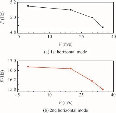
Fig.16 Horizontal mode tested in the gust experiment.
Wing structural displacement responses in the test were obtained from the 3-D camera measurement.The camera assumed the first photo it took as the benchmark(de flections were zero)and other structural de flections were compared with it,so the de flections in test results have uncertain signs and only the relative de flections are meaningful.The three directional de flections of the wing tip obtained from the camera under a certain gust frequency but at various wind speeds are presented in Fig.17.Although the modal frequency changed under different wind speed cases,the increased wind speed and the resulting increased aerodynamic load became the main reasons that made the wing tip de flection increased along with the wind speed.The flow and the wing in the theoretical nonlinear gust response analysis simulation are presented in Fig.18.The red frame zone represents the wing and the black zone represents the wake flow.The corresponding gust response simulation results obtained via the time-domain analysis are compared in Fig.19.Despite of the phase difference,the stable response amplitudeAis quite close between the test result and the theoretical analysis result.Once the wind speed is fixed,the gust frequency’s diversi fication effect on the wing tip de flection is obvious in Fig.20.When the gust frequency is 5.5 Hz,which is close to the structural 1st horizontal bend frequency,the wing tip de flection is larger than those at the other two frequencies especially in the chordwise direction.This can be validated in the nonlinear response analysis shown in Fig.21,in which two directional de flections of the wing tip under different frequency gust excitations obtained by the nonlinear gust response analysis are presented.
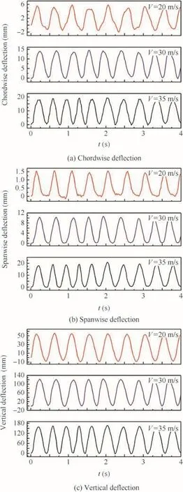
Fig.17 Tested gust wing tip de flection responses at different wing speeds(F=2 Hz).

Fig.18 Gust response analysis simulation.

Fig.19 Analysis and test results of vertical wing tip de flections under different wind speeds(F=2 Hz).
The oscillating amplitudes of the wing tip under different gust frequencies are quite different.When the gust frequency is near the vertical mode frequency,the vertical deformation increases fast and reaches to an extremum.The chordwise de flection reaches the extremum when the gust frequency is about 5 Hz,which is quite near the structural horizontal mode frequency.Fig.22 shows the nonlinear analysis results marched in the time domain.The curve’s initial value presents the nonlinear static de flections under a 20 m/s steady flow.When the 5.5 Hz continuous gust encounters,the structure has a few periodic transient responses,during which the oscillating amplitude changes obviously.After that,the structural response tends to be steady and its oscillating amplitude is consistent with the test results in Fig.20.These fair to good quantitative agreements between theoretical and experimental results demonstrate that the presented analysis method is an acceptable way to predict the geometrically nonlinear gust response for flexible wings.

Fig.20 20 m/s wing tip de flection responses at different gust frequencies in the test.

Fig.21 Wing tip oscillating amplitudes under different gust frequencies at 20 m/s.

Fig.22 20 m/s wing tip vertical de flection responses under 5.5 Hz gust.
5.Conclusions
A theoretical geometrically nonlinear aeroelastic analysis framework is established and the correlative wind tunnel validating test is introduced in this paper.The analysis framework can deal with the stability aeroelastic problem and gives notable large structural deformations that are consistent with the wind test results.The most important is that a time-domain aeroelastic gust response analysis is implemented by the UVLM coupled with nonlinear structural dynamics.These two methods are marched in the time domain and in each transient dynamic computation time step,and the aerodynamic surface and geometric exact boundary condition are updated automatically to make the analysis continuous and corresponding with the actual physical scene.A wind tunnel test for a single flexible wing with novel experiment techniques and measurements were conducted to present the special geometrically nonlinear phenomena and validate theoretical analysis results.In this wind tunnel experiment,nonlinear flutter and gust response tests were conducted on the largely deformed wing structure.Both the theoretical and experimental results indicated that large structural deformations and aerodynamic loads may alter the structural characteristics,making the horizontal mode stiffness decline.Thus the horizontal mode may signi ficantly change the flutter coupling form and cause the critical flutter speed decline.The very flexible wing has different gust response characteristics under different deformations and load conditions,which linear analysis is hard to demonstrate.Although the tested model may not possess and present all the typical geometrically nonlinear characteristicsthatweredesired,the experimentaltechniques,measurements,and theoretical analysis methods can be treated as useful references for other very flexible wing experiments.Compared with test results,the time-domain aeroelastic response analysis is reliable,and the easy programing and the adaptability to complex structure models make the theoretical analysis framework to be easily used in engineering analysis.Future work may focus on typical very flexible aircraft’geometrically nonlinear aeroelasticity using time-domain analysis methods to illustrate special problems such as dynamics response and limit cycle oscillation(LCO).
Acknowledgements
This work was supported by the National Natural Science Foundation of China(Nos.11302011,11172025)and the National Natural Science Foundation for Youth of China(No.11402013).
1.Patil MJ,Hodges DH.On the importance of aerodynamic and structural geometrical nonlinearities in aeroelastic behavior of high-aspect-ratio wings.J Fluids Struct2004;19(7):905–15.
2.Patil MJ.Nonlinear gust response of highly flexible air-craft.Reston:AIAA;2007,Report No.:AIAA-2007-2103.
3.Tang D,Grasch A,Dowell EH.Gust response for flexibly suspended high-aspect ratio wings.AIAA J2010;48(10):2430–44.
4.Su W,Cesnik CES.Dynamic response of highly flexible flying wingsProceedings of the 47th AIAA/ASME/ASCE/AHS/ASC structures,structuraldynamicsandmaterialsconference.Reston:AIAA;2006.p.412–35.
5.Guo D,Xu M,Chen SL.Nonlinear gust response analysis of free flexible aircraft.Int J Intell Syst App(IJISA)2013;5(2):1–15.
6.Noll TE,Ishmael SD,Henwood B.Technical findings,lessons learned,and recommendations resulting from the helios prototype vehicle mishap.Washington,D.C.:National Aeronautics and Space Admin Langley Research Center Hampton VA;2007.
7.Smith MJ,Patil MJ,Hodges DH.CFD-based analysis of nonlinear aeroelastic behavior of high-aspect ratio wings.Reston:AIAA;2001,Report No.:AIAA-2001-1582.
8.Herting DN.MSC/NASTRAN advanced dynamic analysis user’s guide.Newport Beach:MacNeal-Schwendler Corporation;1997.
9.Song TX.Nonlinearstructurefiniteelementcomputation.Wuhan:Huazhong University of Science&Technology Press;1996,p.18[Chinese].
10.Wang XC,Shao M.Theory and numerical methods of finite element method.Beijing:Tsinghua University Press;1997,p.539[Chinese].
11.Xie CC,Yang C.Linearization method of nonlinear aeroelastic stability for complete aircraft with high-aspect-ratio wings.Sci China Ser E-Tech Sci2011;54(2):403–11.
12.Blakely K.MSC/NASTRAN basic dynamic analysis user’s guide.version 68.Newport Beach:MacNeal-Schwendler;1993.
13.Hensse H.Consistent aeroelastic linearization and reduced-order modeling in the dynamics of maneuvering flexible aircraft[dissertation].London:Imperial College London;2013.
14.De Souza CE,Silva RGA,Cesnik CES.Nonlinear aeroelastic framework based on vortex-lattice method and corotational shell finite elementProceedings of the 53rd structures,structural dynamics,and materials conference(SDM).Reston:AIAA;2012.
15.Katz J,Plotkin A.Low-speed aerodynamics.New York:Cambridge University Press;2001,p.488.
16.Shearer CM,Cesnik CES.Nonlinear flight dynamics of very flexible aircraft.J Aircraft2007;44(5):1528–45.
17.Xie CC,Liu Y,Yang C.Theoretical analysis and experiment on aeroelasticity of very flexible wing.Sci China Technol Sci2012;55(9):2489–500.
18.Liu X,Wu Z,Yang C.Flow field analysis and experimental investigation on gust generator.J Beijing Univ Aeronaut Astronaut2010;36(7):803–7[Chinese].
19.Chu LF,Liu XY,Wu ZG.The design and application of gust generator for gust alleviation model wind tunnel test.In:The 11th National aeroelastic conference.2009.
20.Xie CC,Wang LB,Yang C,Liu Y.Static aeroelastic analysis of very flexible wig based on non-planar vortex lattice method.Chin J Aeronaut2013;26(3):514–21.
 CHINESE JOURNAL OF AERONAUTICS2016年1期
- CHINESE JOURNAL OF AERONAUTICS的其它文章
- Plastic wrinkling prediction in thin-walled part forming process:A review
- Progress of continuously rotating detonation engines
- Microstructure control techniques in primary hot working of titanium alloy bars:A review
- A hybrid original approach for prediction of the aerodynamic coefficients of an ATR-42 scaled wing model
- Dynamic modeling and analysis of vortex filament motion using a novel curve- fitting method
- Boundary-layer transition prediction using a simpli fied correlation-based model
