Characteristic analysis of lock-in for an elastically suspended airfoil in transonic bu ff et flow
Quan Jingge,Zhang Weiwei,Gao Chuanqiang,Ye Zhengyin
School of Aeronautics,Northwestern Ploytechnical University,Xi’an 710072,China
1.Introduction
In transonic flow,due to the shock-boundary-layer interaction,the self-sustained,low frequency,large amplitude shockoscillations along the airfoil chord are observed for certain combinations of Mach number and mean angle of attack,even in the absence of airfoil motion.We de fine it as shock buffet.The transonic buffet flow is so highly unsteady and nonlinear,making the corresponding study on flow stability dif ficult and complicated.So far,there is not yet a clear mechanism which can fully explain the transonic shock buffet phenomenon.Lee1proposed a self-sustained feedback model to explain the mechanism of shock oscillation,but there were some defects.Crouch et al.2,3provided a new perspective to study the mechanism of transonic buffet from the view of global instability,but still had its flaw.The actual transonic shock buffet mechanism is still a subject of discussion and worthy of a long deep fine study.num
F eorri c a al l soi nm gu lta itmi oen, a resl eaar g rce h e nsu6m–11b earr e o f ca e rxr p iee dri m oue tn tosn4,5tra anndsonic shock buffet phenomena,but mostly focus on the rigid airfoil and always study the prediction of the buffet onset.There are less studies on the transonic buffet characteristics of the elastic airfoil,even less on the buffet responses.In the classic concept of aeroelasticity,buffet is usually de fined as forced vibration.Under this condition,the aerodynamic loads have no relation with structure motion,so it is not necessary to analyze buffet by coupling the aerodynamic loads with structure motion.The in fluences of the structural elastic mode on flow characteristics and aeroelastic responses can be ignored.However,the practical aerodynamic load is not only related to flow state(Mach number,angle of attack,dynamic pressure,et al.),but also associated with structure vibration more or less.The airfoil structural motion can affect flow characteristics to a certain extent and present obvious fluid-structure interaction characteristic.Steimle et al.12carried out unsteady transonic flow experiments on elastic wing.It is clearly shown that the interaction of shock/boundary-layer and separated flow produces huge pressure fluctuations and also results in a strong fluid-structure coupling.Therefore,the elastic effect of the airfoil and the associated buffet response problem should not be ignored in transonic buffet analysis.
In recent years,numerical simulations have been carried out to investigate the effects of prescribed airfoil harmonic oscillation on flow patterns and responses characteristics via uncoupled method and the lock-in phenomenon has been observed.Raveh and Dowell13,14simulated the response of a prescribed oscillation airfoil in transonic buffet flow and found that lock-in occurred when the shock buffet frequency synchronized with the prescribed airfoil pitch motion frequency and the amplitude was above a certain threshold.The system response predominantly assumed the frequency of the airfoil motion.Iovnovich and Raveh15found that resonance and phase lead appeared near the buffet onset when the airfoil forced movement frequency was close to the buffet frequency.Nitzsche and Giepman16studied the aerodynamic resonance response of a two-dimensional(2-D)airfoil under pre-buffet flow conditions to prescribed harmonic flap,pitch,and translational motions.Young and Lai17found the vortex lock-in phenomenon in the case of an oscillating airfoil in plunge at Reynolds number of 2.0×10⁴.Harmann et al.18carried out experiments to study the in fluence of coupled heave and pitch oscillations in the transonic flow.It was found that at forced oscillation at excitation frequencies in the buffet range,the shock oscillation locked into the excitation frequency indeed.Although the above-mentioned studies considered the in fluence of structure vibration on flow characteristic and found the lockin phenomenon,they did not analyze the effect of the elastic mode on the buffet flow and response characteristics.
When considering the elastic effect of the structure,the structural movement and the shock buffet oscillation will be interacted with each other,having a signi ficant impact on the transonic buffet flow and aeroelastic responses.Raveh and Dowell19firstly studied the aeroelastic response of an elastically suspended airfoil in transonic buffet flow using RANS solver and found the frequency lock-in occurs,when the frequency of the elastic system is close to the buffet frequency and the oscillation amplitude is above some threshold.The study is useful and directive for the lock-in research of an elastic airfoil in transonic buffet flow.
In current study,an aeroelastic system comprised of a NACA0012 airfoil,suspended on a pitch spring,is simulated in transonic buffet flow by coupling the unsteady flow solver with structural motion equation.The work focuses on the characteristic analysis of the lock-in phenomenon,which can be observed in the responses of an elastic airfoil in transonic buffet flow.A series of computations is carried out to mainly study the frequency range of lock-in and the in fluences of the structural natural frequency,mass ratio and the structural damping on the lock-in characteristics in detail.
2.Numerical method
2.1.Unsteady flow solver
The unsteady transonic buffet flow is simulated by a finite volume method for the unsteady RANS solver.Xiao7,Iovnovich8and Barakos et al.9have used the RANS equations to investigate the buffet flow around several 2-D airfoils and have good agreements with experiment datas,which demonstrate that current RANS has good capability to capture shock buffet phenomenon.
Based on Morkovin’s assumption,the RANS equations ignore density fluctuations,and approximate turbulence flow as the sum of a mean steady flow and a small-disturbance unsteady flow,which is represented by a turbulent model.The two-dimensionalintegralgoverning equations for unsteady Reynolds-averaged Navier-Stokes equations are expressed as20,21

where Ω is the control surface element,Sthe surface,tthe time,Γ the boundary of the control surface element,and n the identity normal vector.Q,F(Q,Vgrid),G(Q)represent the conservation vector,the inviscid flux vector considering grid moving velocity,and the viscous flux vector respectively.Vgridis the moving grid velocity vector.By dimensional analysis,the equations can be expressed in terms of dimensions of the chord length,free stream density,speed of sound,as well as temperature.
The AUSM+up scheme is adopted for spatial discretization to capture the shock discontinuity accurately and suppress numerical oscillations in space.An implicit dual-time stepping method is used for time discretization to ensure that the numerical method has second-order accuracy in time.At sub-iteration,the fourth stage Runge–Kutta scheme is applied with local-time stepping,also using the residual smoothing technique and multi-grid for convergence acceleration.
The Spalart–Allmaras(S–A)turbulence model is used for all computations.S–A model has good robust and numerical convergence,which can well simulate the attached flow and thin free shear layer flow.
The grid deformation is realized by a radial basis functions(RBF)interpolation scheme.22In order to avoid additional error caused by grid motion,the geometric conservation law is introduced.
2.2.Structural equation of motion
The aeroelastic equation of motion of the one-degree-offreedom pitch system for the elastically suspended airfoil is

where α is the pitch angle of attack,ωαthe pitch natural frequency,and ζ non-dimensional structural damping.The airfoil moment of inertia can be expressed as,in whichmis mass,rαthe non-dimensional radius of gyration about elastic axis,andbsemi-chord length.The pitch moment term is,assuming the center of pressure as its integrated point.ρ∞,v∞,Cmrepresent the free-stream density,free-stream velocity,and theairfoilmomentcoef ficient respectively.
By de fining the non-dimensional time τ= ωαt,mass ratiopitch reduced frequencyand nondimensional velocitywe have the dimensionless aeroelastic motion equation of Eq.(2)as follows:

For solving the Eq.(3)simply,the state space method is used to transform Eq.(3)into first-order ordinary differential equations with initial conditions known.By de fining a structural state-vectorthe structural equation in state-space form is

This paper uses a four-order hybrid linear multi-step scheme23to solve Eq.(4),which has been proved of a high ef ficiency and precision,as well as a good stability.
3.Validation of method
3.1.Test case 1:Vortex-induced vibrations of an elastically mounted cylinder
The lock-in phenomenon is earliest observed in vortex-induced vibrations behind a cylinder.Numerical and wind tunnel investigations24–27have been carried out to study the vortex-induced vibrations of a circular cylinder mounted on elastic supports and it is found that the lock-in occurs when the cylinder vibration frequency matches the vortex shedding frequency.
To ascertain the accuracy of current numerical method and its implementation,the vortex-induced vibrations of an elastically mounted cylinder in two dimensions are simulated at low Reynolds number.The cylinder is free to vibrate in both transverse and in-line directions,with a low non-dimensional mass equal to 10.The Reynolds number is fixed(Re=100)and the reduced natural frequencyFnis varied(Fn=fnD/U∞,Dis the diameter of the cylinder,U∞is the free-stream velocity andfnis the nature frequency of the cylinder).
The numerical grid is a hybrid unstructured mesh with quadrilateral cells in boundary layer region,as shown in Fig.1.The computational domain is 60D×40D,with the above twenty thousand points.
As the amplitude of transverse vibrations is much higher than those of in-line oscillations,here we just show the results of the cylinder transverse vibrations.Fig.2 shows the variation of the transverse displacement of the cylinder with the reduced natural frequency,in whichAis the amplitude of the cylinder variation.The cylinder exhibits self-excited oscillations beyondFn=0.12.The maximum amplitude is achieved atFn=0.20 and the cylinder ceases to vibrate beyondFn=0.22.Fig.3 shows the coupling reduced frequency of the cylinder changes with the reduced natural frequency.When the reduced natural frequency is below 0.12 or above 0.22,the cylinder coupling reduced frequency matches the vortex shedding frequency(the Strouhal numberStfor the stationary cylinder atRe=100 is about 0.166).The cylinder exhibits forced vibration induced by the vortex shedding.When the reduced natural frequency is between 0.12 and 0.22,the cylinder coupling reduced frequency synchronizes with the reduced natural frequency.The lock-in is observed.
All the results are in good agreement with those of Singh and Mittal27,indicating that our computational method is effective and accurate to simulate the lock-in phenomenon.

Fig.1 Numerical grid of cylinder.
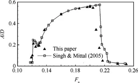
Fig.2 Transverse displacement of cylinder at various reduced natural frequencies.
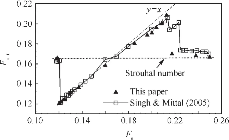
Fig.3 Coupling reduced frequency of cylinder at various reduced natural frequencies.
3.2.Test case 2:Prediction of shock buffet onset of a rigid airfoil
The transonic buffet flow over a NACA0012 airfoil at Mach number of 0.70 and Reynolds number of 3.0×10⁶is simulated to verify the effectiveness of current numerical method in simulating transonic buffet flow.The computational grid is a 2-D hybrid unstructured mesh with quadrilateral cells in the expected boundary layer region and triangles in outer field.The far field extends 20 chords away from airfoil surface.The computational domain has 200×36 points in boundary layer region and the total nodes are about ten thousand.
Fig.4 shows the lift and moment coef ficient time history at different angles of attack withMa=0.7,Re=3.0×10⁶.For the small mean angle of attack of 4.6°,the amplitudes of the lift and moment coef ficient responses tend to be zero,which means that the flow is steady.For the mean angle of attack of 4.7°,the aerodynamic responses begin to oscillate apparently,hinting that the flow is unsteady and shock buffet occurs,although the amplitude is a little small.For the mean angle of attack of 4.8°,the lift and moment responses have dramatic oscillation with a large amplitude of ΔCl=0.036,as a result of the present shock buffet.So the shock buffet onsetis αm=4.7°fortherigid NACA0012 airfoilatMa=0.7,Re=3.0×10⁶.This result agrees well with the wind tunnel experiment datas28.
Fig.5 shows the pressure contours at different time instants of a cycle at mean angle of attack of 4.8°.It is seen that the location of shock changes with time.The shock oscillation is clear.
Fig.6 presents the frequency content of the lift and moment coef ficient responses atMa=0.7, αm=4.8°.Both of them have a main peak at the same reduced frequency of 0.18,which is the buffet reduced frequency and agrees well with the experiment datas28.Besides,the moment coef ficient response still consists of another much smaller peak at a high frequency equal to 0.36,which is twice the buffet reduced frequency.
Simulations are repeated for a Mach number range of 0.7–0.78 at various angles of attack including the onset of shock buffet.Fig.7 shows the prediction results of the shock buffet onset boundary by current numerical method and compares them with the experimental datas.28Both of them are in good agreement.
Based on this validation,it is concluded that good prediction of the buffet onset conditions can be achieved via current numerical method.

Fig.4 Lift and moment coef ficient time history at different angles of attack with Ma=0.7,Re=3.0×10⁶.
4.Aeroelastic analysis of an elastically suspended airfoil
As we know,the shock buffet onset is always a function of Mach number and mean angle of attack.For a rigid airfoil,once buffet occurs at a speci fic Mach number and angle of attack,the vortex flow characteristic is determined and has a uniquenaturalfrequency,which resemblesthe natural frequency of the structure,usually de fined as the shock buffet reduced frequency.When the airfoil is flexible,the unsteady aerodynamic forces,induced by the shock wave oscillation and shock-induced flow separation,exert on the airfoil and result in the airfoil vibration.As the shock buffet frequency is close to the structural natural frequency of the airfoil,resonance may take place within the elastic system.Besides,the airfoil elastic vibration can affect the flow pattern also.They interact with each other,and induce signi ficant aeroelastic responses.Under some conditions,the airfoil elastic vibration may be so large that it may interfere with and control flow pattern,making the elastic system frequency lock into the structural frequency.The lock-in occurs.
The computation case in the current study is that of a NACA0012 airfoil,suspended on a pitch spring in transonic buffet flow.All simulations are performed at Mach number of 0.70 and Reynolds number of 3.0×10⁶,with a mean angle of attack of α =4.8°,for which buffet exists with a reduced frequency ofkf=0.18.The numerical grid uses the same grid in Section 3.2.The computational domain is covered by hybrid unstructured grid with quadrilateral cells in boundary layer,extending approximately 20 chords away from the pro file.
By current numerical methods,the characteristic of lock-in,which will be present in aeroelastic responses of the elastic airfoil in transonic buffet flow,is studied dominantly.High emphases are put on the frequency range of lock-in,and the effects of the three parameters,which are the structural natural frequency,mass ratio and structural damping,on lock-in characteristics of the elastic system.

Fig.5 Pressure contours at different time instants of a cycle at mean angle of attack of 4.8°,Ma=0.7,Re=3.0× 10⁶.
Before further study,three different and important parameters need to be introduced in advance.They are the structural natural reduced frequency in pitch motionkα,the shock buffet reduced frequencykf,and the coupling elastic system reduced frequencyks-fIn the later section,they will present many times,so we should keep their differences in mind to avoid confusion.Moreover,all the frequencies present in current paper are non-dimensional reduced frequency.
4.1.Frequency lock-in phenomenon of an elastically suspended airfoil in transonic buffet flow
To investigate the aeroelastic responses of the elastic system in transonic buffet flow,simulations are performed with fixed mass ratio and various natural frequencies,ranging from below to above the shock buffet frequency,as well as neglected structuraldamping.The simulation conditions are at

Fig.6 Frequency content of aerodynamic responses at mean angle of attack of 4.8°,Ma=0.7,Re=3.0 × 10⁶.
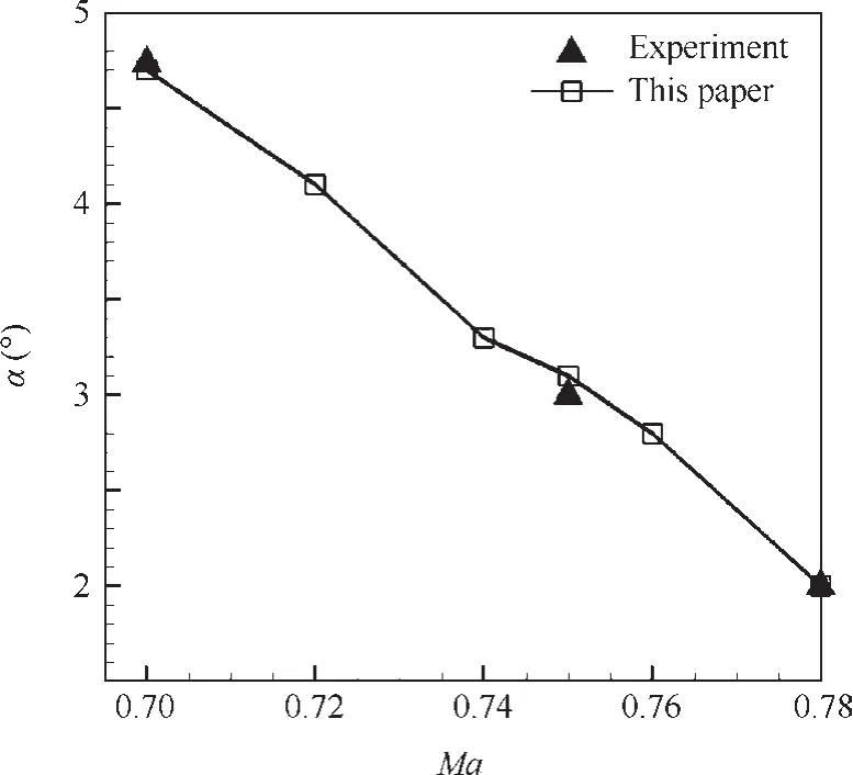
Fig.7 Transonic buffet onset boundary for a rigid NACA0012 airfoil.

Fig.8 Coupling frequency of elastic system at different structural natural frequencies with μ =200,ζ=0.

Fig.8 shows the coupling frequency of the elastic system at different structural natural frequencies.It is shown that as the structural natural frequency changes,the elastic system exhibits different patterns in different regions.
When the structural natural frequency is far lower than the buffet frequency,the elastic system coupling frequency is equal to the buffet frequency,namelyks-f=kf=0.18.As shown in region I.The airfoil exhibits forced vibration with small amplitude,so the in fluence of elastic motion on transonic buffet flow is much weak.
When the structural natural frequency is close to the buffet frequency,the elastic system coupling frequency is no longer equal to,but slowly deviates from the buffet frequency,and shifts towards the structural natural frequency,then finally keeps the same value as the structural natural frequency,namelyks-f=kα.The lock-in occurs.Whereas,when the structural natural frequency is far away from the buffet frequency,the elastic system coupling frequency still locks into the structural natural frequency.The lock-in keeps present until the structural nature frequency is near the double buffet frequency,as shown in region II.
Then,when the structure natural frequency continually increases up to a considerable value,as shown in region III,which is far larger than the double buffet frequency,the system coupling frequency will ultimately leave the structure natural frequency and return back to the buffet frequency,namelyks-f=kf.The lock-in phenomenon vanishes.
The results of Fig.8 show that as the structural natural frequency changes,the aeroelastic characteristic of the elastic system experiences the lock-in phenomenon.The lock-in presents in a wide range,of which the lower threshold is near the buffet frequency,while the upper threshold is near the double buffet frequency.It is apparent from this figure.In the range of lockin,the system coupling frequency keeps the same value as the structural natural frequency.Beyond the range of lock-in,the system coupling frequency moves back to the buffet frequency.
Figs.9–11 present the aeroelastic responses of the elastic system and thecorresponding powerspectrum density(PSD)analysis at different structural natural frequencies in detail.

Fig.9 Aeroelastic responses and frequency content of elastic system at kα≪ kf.
It can be seen from Fig.9 that when the structure natural frequency is much smaller than the buffet frequency,corresponding to region I in Fig.8,the pitch angle of attack and moment coef ficient curves exhibit a harmonic vibration and the amplitudesrise asthe structure naturalfrequency increases.The system reaches limit cycle oscillation(LCO).The pitch oscillation is just of a very small angle,so it is not enough to affect the transonic buffet flow characteristic.The responses behave forced vibration,and the system coupling frequency is equal to the buffet frequency.Fig.9(c)shows the corresponding frequency content of moment coef ficient.It is seen that the flow has a main peak at the buffet frequency and a secondary smaller peak at the double buffet frequency,as well as other weak higher harmonics.
When the structure natural frequency is in the vicinity of the buffet frequency,as seen in Fig.10,the pitch angle and moment coef ficient curves spread slowly to a weak harmonic vibration,and the system goes into a weak LCO.With the closeness of the structure natural frequency to the buffet frequency,the system reaches resonance and the response amplitude increases.The airfoil elastic motion is large enough to interfere with and control the flow pattern,causing the elastic system frequency to lock into the structural natural frequency.The lock-in occurs.So the frequency content of moment response is shifted from the buffet frequency towards the structure natural frequency and has a double frequency component and other high frequency components,as shown in Fig.10(c).
When the structural natural frequency is near the double buffet frequency,the pitch angle response is divergent and the divergence speed falls with the structural natural frequency increasing.While the responses of moment coef ficient always experience a short period of convergent oscillation at lower frequency firstly,and then diverge slowly with high and low frequencies coexistence,at last totally develop into a high divergent oscillation.As the structural natural frequency increases,the divergence speed and the amplitude fall,but the time of the initial convergent oscillation persists longer.Fig.11(c)and(d)show the clear time history of moment coef ficient atkα=0.33 and 0.39 respectively.By contrast,the period of convergent oscillation atkα=0.33 is very short and the system quickly comes into high-frequency divergent oscillation.While,the momentcoef ficientresponse atkα=0.39 beats in cucurbit shape in the first and lasts long before divergence.Frequency analysisofthe moment coef ficient response in different time periods is conducted.In the first period of the simulation,the pitch angle is so small that it does not affect flow;therefore the flow is dominated by the shock buffet.The moment response is mainly at the buffet frequency only.In the second period of the simulation,the frequency content of the moment coef ficient shows less power in the buffer frequency and more power in the structural natural frequency.It means that as pitch angle grows,the buffet frequency gets weak,while the structural natural frequency becomes strong.Finally,in the last period,the moment frequency content is solely in the structural natural frequency.For this time period,the structural natural frequency dominant in the flow and the buffet frequency vanishes.The lockin phenomenon occurs.

Fig.10 Aeroelastic responses and frequency content of elastic system when structure frequency is close to buffet frequency.
Fig.11(e)presents the frequency content of moment coef ficient with whole time segment at different structural natural frequencies.It can be seen two distinct frequencies,the main structural natural frequency and the secondary buffet frequency,as well as other higher harmonic frequencies.The system is highly nonlinear.
Different from the responses of lock-in in Fig.10,the system responses do not behave a harmonic vibration any more to reach limit cycle oscillation,but exhibit divergent instability.And,the moment coef ficient responses exhibit the fluid and structural mode interaction and competition with each other,as the whole process of moment coef ficient atkα=0.39 distinctly displays.
Following lock-in,when the structural natural frequency increasesuptoasuf ficientlylargevalue,farhigherthanthedouble buffet frequency,the pitch angle and moment coef ficient curves spread back to a harmonic vibration,as shown in Fig.12.ThesystemgoesintoLCOagain.Thepitchangleamplitudeissosmall,reducingbyabout1–2level,thatithasnoimpact on flow pattern.The moment coef ficient amplitude is not large either,approximately equal to that of the rigid airfoil.The correspondingfrequencycontentofmomentcoef ficientisverysimplex,just has one peak,which is fixed at the buffet frequency.It hintsthatthesystemcouplingfrequencyis finallyawayfromthe structural natural frequency and returns to the buffet frequency again.The lock-in phenomenon vanishes.
4.2.Effect of the mass ratio on lock-in characteristic
Toinvestigatetheeffectofmassratioonlock-incharacteristicof the elastic system,simulation is repeated for another different mass ration μ =1000,by using the above same method and computational state.The structural natural frequency varies from 0 to 0.55.

Fig.11 Aeroelastic responses and frequency content of elastic system when structure frequency is near double buffet frequency.

Fig.12 Aeroelastic responses and frequency content of elastic system when structure frequency is far higher than double buffet frequency.

Fig.13 Coupling frequency of elastic system at different structural natural frequencies with μ =1000 and μ =200.

Fig.14 Coupling frequency of elastic system at different mass ratios with kα=0.30,ζ=0.
Fig.13 shows the elastic system coupling frequency at various structural natural frequencies.It is shown that when the structural natural frequency is close to the buffet frequency,the system coupling frequency is equal to the structural natural frequency.The lock-in presents.The broad range of lock-in for the structural natural frequency is 0.18<kα<0.33.When the structural natural frequency is beyond the range(kα< 0.18 orkα> 0.33),the lock-in disappears,and the system coupling frequency is back to the buffet frequency again.
By contrasting the results with those at μ=200,the aeroelastic response of the elastic system exhibits similar pattern and the lock-in appears and vanishes as the structural natural frequency changes.But differently,as mass ratio increases,the frequency range of lock-in gets narrow,with the upper threshold decreasing.However the lower threshold is always keeping the same.

Fig.15 Aeroelastic responses and frequency content of the elastic system at μ ≥ 1500.
To investigate the effect of mass ratio in detail,simulations arealso conducted with zero structuredamping, fixed structural natural frequency atkα=0.30 and various mass ratios ranging from zero to two thousand.The computational conditions areMa=0.7, αm=4.8°,Re=3.0 × 10⁶,
Fig.14 shows the elastic system coupling frequency at different mass ratios.It is shown that as mass ratio changes,the elastic system exhibits different flow patterns.When mass ratio is lager than 1500,the system coupling frequency is equal to the buffet frequency,namelyks-f=kf=0.18.While,when mass ratio is lower than 1500,the system coupling frequency locks into the structural natural frequency, namelyks-f=kα=0.30.The lock-in occurs.However,interestingly,when mass ratio is much lower than 400,the system coupling frequency is no longer equal to,but has a trend to leave away from the structural natural frequency and shifts towards the double buffet frequency,with mass ratio decreasing.
Figs.15–17 show the aeroelastic responses of the coupling elastic system and the corresponding PSD analysis at different mass ratios in detail.
Mass ratio is the scale of the relative structural stiffness.When mass ratio is very large,the rigidity of the structure will become strong and the flexibility will get weak.The aerodynamic loads may cause very tiny structure elastic vibration,which is not suf ficient to affect the flow property.As shown in Fig.15,when μ ≥ 1500,the curve of pitch angle of attack is a little divergent with small displacement,not enough to in fluence the flow.The moment coef ficient curve reveals harmonic vibration.Fig.15(c)shows the frequency content of moment coef ficient at μ=2000.There is only one peak at the buffet frequency.It means that the system coupling frequency is equal to the buffet frequency.The lock-in is not present.
As shown in Fig.16,when 400<μ<1500 the pitch angle of attack curve is divergent,with a high divergence speed increasing with mass ratio falling,and the amplitude is larger than before.The responses of moment coef ficient always experience a period of harmonic vibration at low frequency firstly,then spread slowly with high and low frequencies together,and finally get into divergent oscillation at high frequency.In this case,the system coupling frequency successfully locks into the structural natural frequency.The lock-in appears.The lower the mass ratio is,the quicker the structure elastic vibration spreads,and the shorter the moment coef ficient will experience to reach lock-in.
Taking μ=1000 as an example,Fig.16(c)presents the frequency analysis of the moment coef ficient response at different time periods.In the first segment,the moment coef ficient curve presents harmonic vibration and the buffet frequency dominates the response.In the second segment,the curve spreads slowly,and there are two peak frequency components,less power in the buffet frequency and more power in the structural natural frequency.The coupling frequency of the elastic system shifts towards the structural natural frequency.Finally,in the last segment,the curve diverges,and the response is solely in the structural natural frequency.Fig.16(d)presents the frequency content of the whole time segment.There are two distinct frequencies,the secondary lower buffet frequency and the main higher structural natural frequency.The system coupling frequency gets the same value as the structural natural frequency.The lock-in presents.
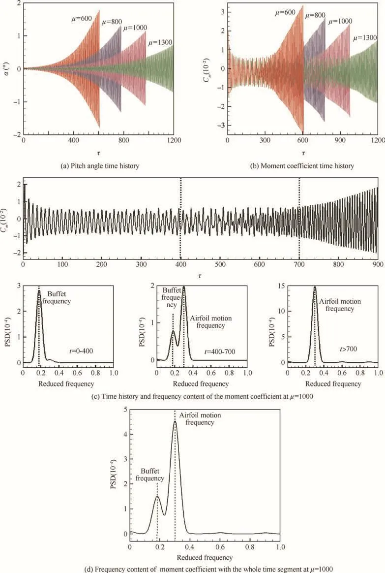
Fig.16 Aeroelastic responses and frequency content of the elastic system at 400<μ<1500.
As mass ratio is much lower than 400,the elastic system comes into divergent instability rapidly.As shown in Fig.17,the divergence speed and amplitude of the pitch angle and moment coef ficient get greater,and the moment coef ficient response does not behave harmonic vibration any more.Differently,the corresponding frequency content of moment coefficient is not equal to,but away from the structural natural frequency,and towards the double buffet frequency as mass ratio gets much smaller.Also,there are higher frequency components in the frequency content.

Fig.17 Aeroelastic responses and frequency content of elastic system at μ < 400.

Fig.18 Time histories of pitch angle and moment coef ficient of elastic system at kα=0.30,μ =200,no structural damping.
4.3.Effect of structural damping on lock-in characteristic
The structural damping has an effect on the stability of the elastic system,but it is ignored in the above computations.Figs.18 and 19 show the aeroelastic responses of the elastic system with zero and added 1%structural damping respectively.The mass ratio and structural natural frequency are fixed.For the system with zero damping,the response is divergent.However,the responses with 1%damping diverge slowly and finally tend to be limit cycle oscillation.The structural damping delays the growth speed of the responses and reduces the amplitudes.
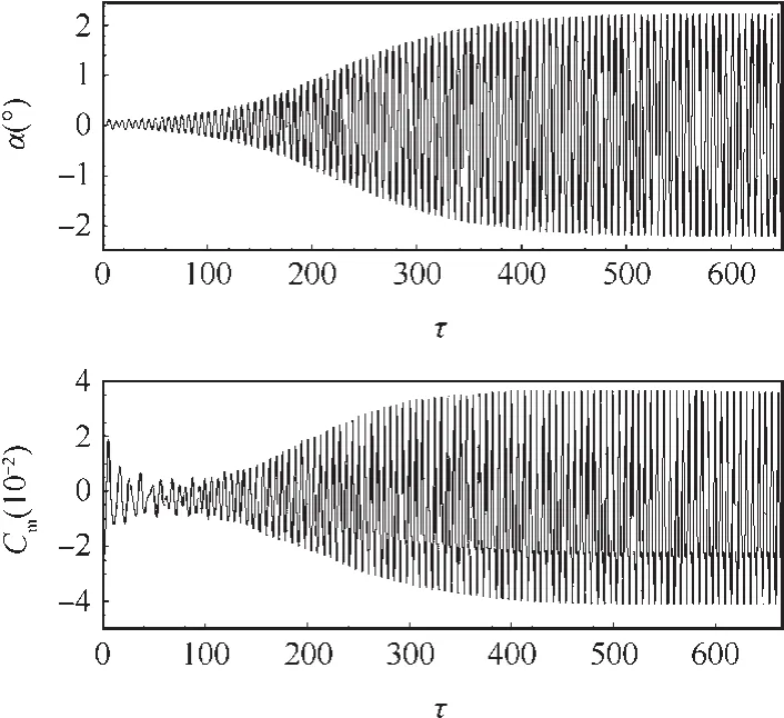
Fig.19 Time histories of pitch angle and moment coef ficient of elastic system at kα=0.30,μ =200,1%structural damping.
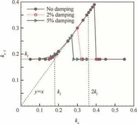
Fig.20 Frequency range of lock-in of elastic system at various structural damping with μ=200.
Fig.20 presents the frequency range of lock-in of the elastic system at various structural damping.The mass ratio is fixed at μ=200.As the structural damping increases,the range of lock-in gets narrow.The beginning point of the lock-in present almost keeps the same value,while the ending point decreases with the damping increasing.
5.Conclusions
In the current work,the lock-in characteristic in transonic buffet flow of an elastic airfoil is mainly concerned.Numerical simulations are performed to study the range of lock-in and the effects of the structural natural frequency,mass ratio and structural damping on lock-in characteristic.
(1)As the structural natural frequency changes,the aeroeal
stic responses of the elastic system in transonic buffet flow experience the lock-in phenomenon.The lock-in occurs as the structural nature frequency is close to the buffet frequency,and stays present until the structural nature frequency is near the double buffet frequency,and then vanishes when the structural nature frequency is far away the double buffet frequency.It hints that the lock-in presents in a wide range from near the buffet frequency to the double buffet frequency,with the elastic system coupling frequency equal to the structural natural frequency.
(2)The mass ratio and structural damping have a great impact on the frequency range of lock-in.The lower the mass ratio and structural damping are,the wider the range of lock-in will be.As the mass ratio and structural damping decrease,the upper threshold of lock-in gets greater,but the lower threshold almost never changes,which is always near the buffet frequency.
Further work will be carried out to study the lock-in mechanism by analyzing the eigenvalue of the system with unstable dynamic model.
Acknowledgement
This study was supported by the project of the National Natural Science Foundation of China (No. 11272262).
1.Lee BHK.Self-sustained shock oscillations on airfoils at transonic speeds.Prog Aerosp Sci2001;37(2):147–96.
2.Crouch JD,Garbaruk A,Magidov D,et al.Origin of transonic buffet on aerofoils.J Fluid Mech2009;628:357–69.
3.Crouch JD,Garbaruk A,Magidov D.Predicting the onset of flow unsteadiness based on global instability.J Comput Phys2007;224(2):924–40.
4.Hartmann A,Feldhusen A,Schro¨der W.On the interaction of shock waves and sound waves in transonic buffet flow.Phys Fluids2013;25(2):384.
5.Jacquin L,Molton P,Deck S,Maury B,Soulevant D.Experimental study of shock oscillation over a transonic supercritical pro file.AIAA J2009;47(9):1985–94.
6.Chen LW,Xu CY,Lu XY.Numerical investigation of the compressible flow past an aerofoil.J Fluid Mech2010;643(3):97–126.
7.Xiao Q,Tsai HM,Liu F.Numerical study of transonic buffet on a supercritical airfoil.AIAA J2006;44(3):620–8.
8.Iovnovich M,Raveh DE.Reynolds-averaged navier–stokes study of the shock-buffet instability mechanism.AIAA J2012;50(4):880–90.
9.Barakos G,Drikakis D.Numerical simulation of transonic buffet lf ow using various turbulence closures.Int J Heat Fluid Flow2000;21(5):620–6.
10.Deck S.Numerical simulation of transonic buffet over a supercritical airfoil.AIAA J2005;43(7):1556–66.
11.Thiery M,Coustols E.Numerical prediction of shock induced oscillations over a 2D airfoil:In fluence of turbulence modeling and test section walls.Int J Heat Fluid Flow2006;27(4):661–70.
12.Steimle PC,Karhoff DC,Schro¨der W.Unsteady transonic flow over a transport-type swept wing.AIAA J2012;50(2):399–415.
13.RavehDE,Dowell EH.Frequency lock-in phenomenon for oscillating airfoils in buffeting flows.J Fluids Struct2011;27(1):89–104.
14.Raveh DE.Numerical study of an oscillating airfoil in transonic buffeting flows.AIAA J2009;47(3):505–15.
15.Iovnovich M,Raveh DE.Transonic unsteady aerodynamics in the vicinity of shock-buffet instability.J Fluids Struct2012;29(1):131–42.
16.Nitzsche J,Giepman RHM.Numerical experiments on aerodynamic resonance in transonic airfoil flow.In:Dillmann A,editor.New results in numerical and experimental fluid mechanics.Berlin:Springer-Verlag;2013.p.349–57.
17.Young J,Lai JCS.Vortex lock-in phenomenon in the wake of a plunging airfoil.AIAA J2007;45(2):485–90.
18.Hartmann A,Klaas M,Schro¨der W.Coupled airfoil heave/pitch oscillations at buffet flow.AIAA J2013;51(7):1542–52.
19.Raveh DE,Dowell EH.Aeroelastic responses of elastically suspended airfoil systems in transonic buffeting flows.AIAA J2014;52(5):926–34.
20.Blom F,Leyland P.Analysis of fluid-structure interaction on moving airfoils by means of an improved ALE-method.Reston:AIAA;1997.Report No.:AIAA-1997-1770.
21.Wang G,Jiang YW,Ye ZY.An improved LU-SGS implicit scheme for high reynolds number flow computations on hybrid unstructured mesh.Chin J Aeronaut2012;25(1):33–41.
22.de Boer A,van der Schoot MS,Bijl H.Mesh deformation based on radial basis function interpolation.Comput Struct2007;85(11–14):784–95.
23.Zhang WW,Jiang YW,Ye ZY.Two better loosely coupled solution algorithms of CFD based aeroelastic simulation.Eng Appl Comput Fluid Mech2007;1(4):253–62.
24.Williamson CHK,Govardhan R.Vortex-induced vibrations.Annu Rev Fluid Mech2004;36(444):413–55.
25.Anagnostopoulos P,Bearman PW.Response characteristics of a vortex-excited cylinder at low reynolds numbers.J Fluids Struct1992;6(1):39–50.
26.Carlson HA,Feng JQ,Thomas JP,et al.Computational models for nonlinear aeroelasticity.Proceedings of the 43rd AIAA aerospace sciences meeting and exhibit;2005 Jan 10-13;Reno,Nevada.Reston:AIAA;2005.
27.Singh SP,Mittali S.Vortex-induced oscillations at low reynolds numbers:hysteresis and vortex-shedding modes.J Fluids Struct2005;20(8):1085–104.
28.Barbut G,Braza M,Miller M,et al.NACA0012 with aileron.In:Doerffer P,Hirsch C,Dussauge JP,Babinsky H,editors.Unsteady effects of shock wave induced separation.Berlin:Springer-Verlag;2010.p.101–31.
 CHINESE JOURNAL OF AERONAUTICS2016年1期
- CHINESE JOURNAL OF AERONAUTICS的其它文章
- Plastic wrinkling prediction in thin-walled part forming process:A review
- Progress of continuously rotating detonation engines
- Microstructure control techniques in primary hot working of titanium alloy bars:A review
- A hybrid original approach for prediction of the aerodynamic coefficients of an ATR-42 scaled wing model
- Dynamic modeling and analysis of vortex filament motion using a novel curve- fitting method
- Boundary-layer transition prediction using a simpli fied correlation-based model
