A stepwise optimal design of water network☆
Ying Li*,Jintao Guan
Department of Environmental and Chemical Engineering,Dalian Jiaotong University,Dalian 116028,China
1.Introduction
Water has been used in abundant quantities by chemical,petrochemical,petroleum refining and other process industries.However,increasing cost of wastewater treatment to meet environmental standards and scarcity of good quality industrial water create a serious economic driving force to minimize the amount of water consumption and wastewater discharge.Without fundamental changes to reduce the operations requiring water,three general approaches are usually for wastewater minimization:water reuse,regenerated water reuse,and regenerated water recycle[1].Their definitions are as follows[2].
Reuse:the outlet water from one process,which is sufficiently clean,is directly re-used to satisfy the water demand of another process.
Regeneration reuse:the outlet water from a process is treated to be suitable for use in some water-consuming processes.The treatment is called regeneration.
Regeneration recycle:the regenerated water is re-used in the same process.
The total water network for wastewater minimization is separated into two subsystems for reuse:water utilization network[3–8]and wastewater treatment network[9–13].When the optimal flow scheme only involves the interaction of two subsystems,many opportunities of wastewater minimization such as regeneration reuse are ignored[14].Many efforts have been made to optimal design of water network due to the inherent complexity of two subsystems involving regeneration reuse[15].The pinch technology[16–21]shows limitations to address the complexity of the problem,and the research field moves to mathematical programming methods[22–27].
In order to improve design methods and optimization frameworks for water networks in practice,Alva-Argáez et al.[28]have addressed an integrated approach,which brought the engineering insight with water pinch analysis and powerful mathematical programming tools.Efforts have been made to obtain global optimality for solutions generated from mathematical programming techniques[29,30].Faria and Bagajewicz[31]have discussed the network structure of water system.Teles et al.[32]have proposed new mixed-integer linear programming models for the optimal design of water-using and wastewater treatment networks.However,most of available design methods and approaches have focused on minimizing water consumption and its operating costs.Gunaratnam et al.[33]have developed an automated method for the design of total water systems.Hu et al.[34]have adopted appropriate process decomposition strategies to further reduce freshwater usage and avoid recycling.Iancu et al.[35]have extended the mathematical model of wastewater network for partial/total stream regeneration.
In order to attain zero discharge,regeneration recycle is used in water network design[36].Relvas et al.[37]developed software AquoMin to design and target the networks involving regeneration reuse/recycling.Poplewski et al.[38]established a superstructure for water-using network involving reuse/recycling and solved the superstructure with adaptive random search optimization technique.Kim[39]discussed system analysis tools including a graphical method and an optimization method.Khor et al.[40]proposed a superstructure with fixed topology for a water network consisting of three layers:sources for reuse/recycle,regenerators for contaminant removal,and sinks for acceptance of water for reuse/recycle.Liu's group[41–44]developed a heuristic design procedure for design of water network including regeneration recycle.
Undoubtedly,the introduction of regeneration process can further reduce the consumption of fresh water.Compared with regeneration recycle,regeneration reuse can avoid the risk of potential build-up of trace contaminants in the process.However,the difference between regeneration reuse and regeneration recycle results in a MINLP problem for water network design.For regeneration reuse,the regeneration process cut the water network into two sub-networks before and after the process.Although the research effort in this area has increasingly focused on mathematical programming methods,the solution will be assisted by exploiting insights from conceptual approaches in order to simplify solution procedures.In this paper,a stepwise design approach is developed,in which reuse,regeneration reuse and regeneration recycle are considered step by step and the insights from the design are used to guide the next design.The MINLP problems for regeneration reuse are changed to NLP or LP problems and the recycling water flow rate is minimized.
2.Model Development
2.1.Problem statement
For a set of water-using processes requiring water of a certain quality and a set of regeneration processes with a certain capacity of treating wastewater,it is desired to determine a network of water streams among the processes so that the overall fresh water consumption is minimized while the processes receive water of adequate quality.
For design of water network,the superstructure is so large that it is difficult to solve or find the optimal solutions for corresponding MINLP problem.To simplify the framework of superstructure and find the optimal design of water network,the options for process k to minimize fresh water consumption by a stepwise adoption of reuse,regeneration reuse and regeneration recycle are shown in Fig.1.The head process[4]utilizes only fresh water.Direct reuse process and other processes using fresh water reduce fresh water consumption with the addition of regeneration reuse,which will be considered in Section 2.2.The replacement of regeneration reuse water to fresh water and placement before or after the regeneration process are discussed in Section 2.3.The processes that utilize fresh water except head processes adopt regeneration recycle(Fig.1d).
2.2.Design of water network with direct reuse
For single contaminant systems,processes can be arranged directly in the order of their maximum outlet concentration.However,for multiple contaminant systems,the monotonicity condition of key contaminant must be satisfied.For the process using fresh water only,the contaminant consuming the largest fresh water flow rate is the key contaminant and its outlet concentration attains the maximum for this process.
Usually,the objective function of water network may be the minimization of fresh water consumption.


Fig.1.Options for process k to minimize fresh water consumption.

The optimization platform in this work is the general algebraic modeling system,which is a system with optimization models specified in equation form and their solutions obtained with different solvers.The solvers employed are CONOPT for NLP problem.
2.3.Determination for placement of regeneration process
With regeneration process added,whether regeneration recycle is included must be considered.In regeneration recycle,the same water enters the same process many times,forming similar NLP problem.In regeneration reuse,the same water is allowed to enter the same process once,leading to an MINLP problem for water network design.Binary variables are introduced to account for the water-using processes behind the regeneration process.
Since the difference between the water network involving regeneration and that involving reuse only is an additional stream,when adding the regenerated stream into the network with reuse only,the network involving regeneration is formed.It is necessary to know possible regenerated water flow rate and contaminant concentration.The determination of regeneration process can provide these according to the following rules from reuse water network structure.The design needs to diminish regenerated water flow rater with the minimum fresh water consumption.It means that regenerated water replaces fresh water as much as possible and replaces reuse water as little as possible.
Rule1:Head processes must be placed before the regeneration process.This is decided by definition of head processes in Fig.1(a).
Rule 2:If process i satisfies reuse water demand of process k completely,process k is placed at the same position as process i(before or after the regeneration process).Process k is a total wastewater user as shown in Fig.1(b),which can be satisfied by direct reuse.It is not necessary to consider regeneration reuse for process k in view of fresh water reduction.Meanwhile,the priority of direct reuse is retained by Rule 2 as the simplest method to attain wastewater minimization.
Rule 3:The purpose of setting regeneration process is to replace fresh water with regeneration reuse,so at least one process that uses fresh water must be placed after the regeneration process.If process i and process k are fresh water users and the consumed fresh water of process k is less than that of process i,process k is preferred to be placed before regeneration process.This is the most important step to determine the placement of regeneration process and judge whether the fresh water user processes are placed before or after the regeneration process,as shown in Fig.1(c).
Rule 4:As a special case of Rule 3,if process i sends wastewater to process k,it is not allowed to put process k before the regeneration process and process i after the regeneration process.The stepwise optimal design from reuse to regeneration reuse is shown.
Many regeneration reuse plans are generated according to the processes placement before or after the regeneration process.The regeneration reuse is adopted as an approach to reduce fresh water consumption for process k.At the same time,the reuse water network structure is kept to the largest extent.
2.4.Design of water network with regeneration reuse
Based on these rules,regeneration process is arranged at different positions one by one according to theoretical minimum fresh water consumption.The network structure before the regeneration process is similar to the one in reuse water network.The network structure after the regeneration is optimized through the following NLP model.Regeneration process is normally specified by simply an outlet concentration or a removal ratio.The minimum fresh water consumption and regenerated water flow rate are guaranteed by objective function in whichλαis10times greater thanλβ.Regenerated water flow rate is initialized to be equal to fresh water consumption before the regeneration process.
The objective function of water network:


Table 1 Specified conditions of water using processes for example 1[14]

Table 2 Minimum fresh water consumption of plan design of example 1 for regeneration reuse

Table 3 Specified conditions of water using processes for example 2
2.5.Design of water network including regeneration recycle
In regeneration reuse water network,some processes except head processes that use fresh water will adopt regeneration recycle,toguarantee the minimum recycling water flow rate,which is determined according to the consumed fresh water of head processes.The structure of regeneration reuse water network is kept,and the fresh water consumption except head processes will be replaced by regeneration recycle.For process k in Fig.1(c),the flow rate of regeneration recycle is determined,as shown in Fig.2.

Table 4 Minimum fresh water consumption of plan design of example 2 for regeneration reuse
3.Case Study
Example 1 consists of five water-using processes with single contaminant,given in Table 1 from Kuo and Smith[14].The removal ratio for the regeneration process of 95%is assumed.For single contaminant problem,reuse water network is obtained through a LP model to attain the maximum outlet concentration of each process.In Fig.3,process 1 is head process,processes 2 and 3 need fresh water and the consumption of process 3 is less,process 4 reuses wastewater from process 1 completely,process 5 reuses wastewater produced by processes 2 and 3,and process 2 also sends wastewater to process 3.

Fig.2.The optimal procedure for regeneration reuse water network.

Fig.3.Design of example 1 with direct reuse.
According to the reuse water network,some rules are adopted.
Rule 1:Process 1 is head process and must be placed before the regeneration process.
Rule 2:Process 4 is a direct reuse process and is placed before the regeneration process as process 1.
Rule 3:Among process 2 and 3 at least one process is placed behind the regeneration process.
Rule 4:It is not allowed to place process 3 before the regeneration process and process 2 after the regeneration process simultaneously.Process 5 is a direct reuse process and must be placed after the regeneration process.
Fig.4 shows two plans for regeneration reuse water network design.Plan 1 is the optimal according to the minimum fresh water consumption in Table 2.The corresponding regenerated reuse water network design is shown in Fig.5.It is similar to the result of Liu et al.[41],but the fresh water supplies to process 2 with low contaminant concentration.Otherwise,process 3 can be satisfied by regeneration reuse water and process 2 will be considered with regeneration recycle.

Fig.4.Design plan of example 1 for regeneration reuse.
Based on the regeneration reuse structure,the regenerated water flow rate is 43.68 t·h-1and the recycling water flow rate is 3.68 t·h-1,as shown in Fig.6,which are less than 51.3 t·h-1and 28.8 t·h-1,respectively[14].The regenerated water flow rate is identical to the result of Kuo and Smith[14]of 42.1 t·h-1with a fixed outlet concentration of10 mg·L-1in Fig.7,while the recycling water flow rate is 2.11 t·h-1,which is far less than 35 t·h-1of[14].
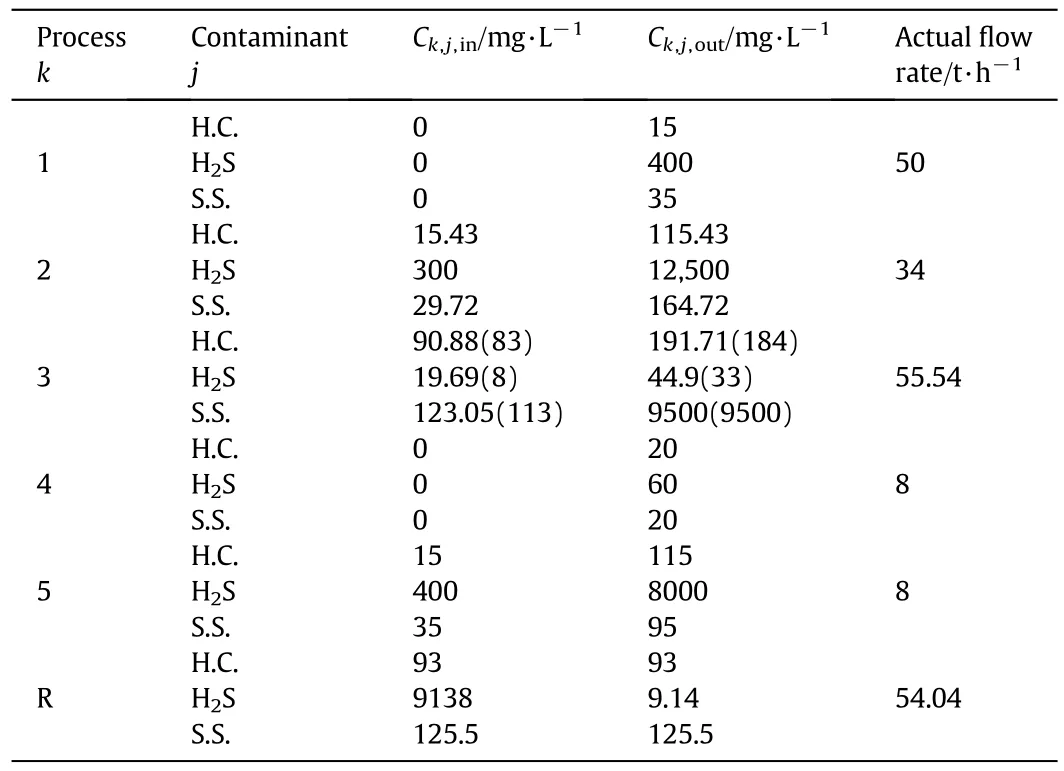
For the water network design problem with multiple contaminants in a simplified petroleum refinery,example 2 is also taken from Kuo and Smith[14].The problem consists of five water-using processes with three contaminants hydrocarbon(H.C.),hydrogen sulfide,and suspended solids(S.S.).Table 3 presents the operating data for the water-using processes and contaminants.The regeneration process is defined in terms of removal ratios,specified to(0,99.9%,0)for the three contaminants.
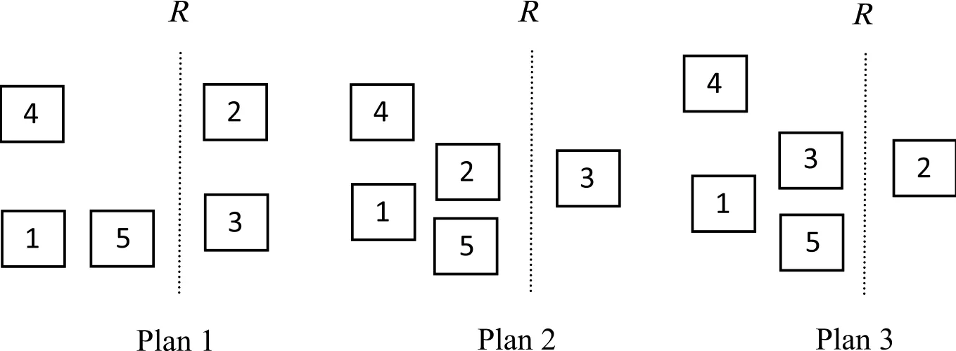
According to NLP model for reuse only,the reuse water network is shown in Fig.8.Processes 1 and 4 are head processes.Process 5 is direct reuse process that reuses wastewater from process 1 completely.Processes 2 and 3 need fresh water and the consumption of process 2 is less.
The rules to place regeneration process are as follows.
Rule 1:Processes 1 and 4 must be placed before the regeneration process.
Rule 2:Process 5 is placed before the regeneration as process 1.
Rule 3:Among processes 2 and 3 at least one process is placed after the regeneration process.And process 2 has priority to be placed before the regeneration process.
Rule 4:No case is used.
Fig.9 shows three plans for regeneration reuse water network design.According to the convergence criterion in Fig.2,fresh water consumption behind the regeneration process equals zero with plan 2 and the total fresh water consumption is less than plan 1 in Table 4.The final regeneration reuse water network of plan 2 is shown in Fig.10.

Fig.5.Design of example 1 for regeneration reuse.

Fig.6.Design of example 1 for regeneration recycle.

Fig.7.Design of example 1 for regeneration recycle at a fixed regeneration outlet concentration of 10 mg·L-1.
Liu etal.[44]and Hu etal.[34]investigated this example with the regeneration reuse.Table 5 compares the results of different methods for this example.Results indicate that the regenerated water flow rate is lower than that in the literature.The final contaminant concentrations and flow rate of the process streams are shown in Table 6.The key contaminant in each process reaches the limiting outlet concentration and the inlet and outlet concentrations of process 3 are closer to the limiting inlet and outlet concentrations compared with the results of Liu et al.[41](in the brackets).The optimal result benefits from the objective function Eq.(6)and the insights from Fig.8 for reuse from processes 1 to 3.

Fig.8.Design of example 2 with direct reuse.

Fig.9.Design plan of example 2 for regeneration reuse.

Fig.10.Design of example 2 for regeneration reuse.

Fig.11.Design of example 2 for regeneration recycle.

Table 5 Comparison of different results for example 2
Meanwhile,process 3 can be satisfied by regenerated reuse water and process 2 is left to supply water with adequate quality by regeneration recycle.For regeneration recycle in Fig.11,the regenerated water flow rate of 55.77 t·h–1is less than that of 56.08 t·h–1in[43].
4.Conclusions
In this paper,a stepwise design of regeneration water network is proposed based on mathematical programming with the insights fromreuse water network structure.For regeneration reuse water network,an MINLP problem is changed to an NLP problem and the searching procedure is simple and effective.Both the minimum fresh water consumption and the minimum regenerated water flow rate are obtained.Furthermore,the regeneration recycle water network featured by minimum recycling water flow rate can be easily provided.Water networks with single and multiple contaminants are designed using the method presented in this paper.Although the fresh water consumption is equal to that in traditional water network,the regenerated water flow rate or the recycling water flow rate is lower than that in literature.Water network involving reuse,regeneration reuse and regeneration recycle is designed step by step in this paper,so the network structure presents better flexibility and operability.

Table 6 The optimal process data for example 2

[1]N.Takama,T.Kuriyama,K.Shiroko,Optimal water allocation in a petroleum refinery,Comput.Chem.Eng.4(1980)251–258.
[2]J.G.Mann,Y.A.Liu,Industrial Water Reuse and Wastewater Minimization,McGraw-Hill,New York,1999.
[3]Y.P.Wang,R.Smith,Wastewater minimization,Chem.Eng.Sci.49(1994)981–1006.
[4]M.J.Savelski,M.J.Bagajewicz,On the optimality conditions of water utilization systems in process plants with single contaminant,Chem.Eng.Sci.55(2000)5035–5048.
[5]M.J.Bagajewicz,M.Rivas,M.J.Savelski,A robust method to obtain optimal and suboptimal design and retro fit solutions of water utilization systems with multiple contaminants in process plants,Comput.Chem.Eng.24(2000)1461–1466.
[6]Y.Li,P.J.Yao,Optimal design of water utilization networks by combination of water pinch analysis and mathematical programming,J.Chem.Ind.Eng.55(2004)220–225.
[7]S.Aly,S.Abeer,M.Awad,A new systematic approach for water network design,Clean Techn.Environ.Policy 7(2005)154–161.
[8]J.P.Teles,P.M.Castro,A.Q.Novais,LP-based solution strategies for the optimal design of industrial water networks with multiple contaminants,Chem.Eng.Sci.63(2008)376–394.
[9]Y.P.Wang,R.Smith,Design of distributed effluent treatment systems,Chem.Eng.Sci.49(1994)3127–3145.
[10]W.J.Kuo,R.Smith,Effluent treatment system design,Chem.Eng.Sci.52(1997)4273–4290.
[11]B.Galan,I.E.Grossmann,Optimal of distributed wastewater treatment networks,Ind.Eng.Chem.Res.37(1998)4036–4048.
[12]H.S.Rogelio,C.F.Julian,M.Z.Ju,Superstructure decomposition and parametric optimization approach for the synthesis of distributed wastewater treatment networks,Ind.Eng.Chem.Res.43(2004)2175–2191.
[13]P.M.Castro,J.P.Teles,A.Q.Novais,Linear program-based algorithm for the optimal design of wastewater treatment systems,Clean Techn.Environ.Policy 11(2009)83–93.
[14]W.J.Kuo,R.Smith,Design of water-using systems involving regeneration,Trans.IChemE 76(B)(1998)94–114.
[15]M.J.Bagajewicz,A review of recent design procedures for water networks in refineries and process plants,Comput.Chem.Eng.24(2000)2093–2113.
[16]S.Mohammadnejad,G.R.NabiBidhendi,N.Mehrdadi,Water pinch analysis in oil refinery using regeneration reuse and recycling consideration,Desalination 265(2011)255–265.
[17]A.A.Ulson de Souza,E.Forgiarini,H.L.Brandãoa,M.F.Xavier,F.L.P.Pessoa,S.M.A.Guelli U Souza,Application of Water Source Diagram(WSD)method for the reduction of water consumption in petroleum refineries,Resour.Conserv.Recycl.53(2009)149–154.
[18]S.R.Wan Alwi,Z.A.Manan,M.H.Samingin,N.Misran,A holistic framework for design of cost-effective minimum water utilization network,J.Environ.Manag.88(2008)219–252.
[19]J.Bai,X.Feng,C.Deng,Graphically based optimization of single-contaminant regeneration reuse water systems,Chem.Eng.Res.Des.85(2007)1178–1187.
[20]J.Bai,X.Feng,C.Deng,Optimal design of single-contaminant regeneration reuse water networks with process decomposition,AICHE J.56(2010)915–929.
[21]J.F.S.Gomes,E.M.Queiroz,F.L.P.Pessoa,Design procedure for water/wastewater minimization:single contaminant,J.Clean.Prod.15(2007)474–485.
[22]A.Alva-Argáez,A.Vallianatos,A.C.Kokossis,A multi-contaminant transshipment model for mass exchange networks and wastewater minimization problems,Comput.Chem.Eng.23(1999)1439–1453.
[23]C.H.Huang,C.T.Chang,H.C.Ling,A mathematical programming model for water usage and treatment network design,Ind.Eng.Chem.Res.38(1999)2666–2679.
[24]M.Tasi,C.Chang,Water usage and treatment network design using genetic algorithm,Ind.Eng.Chem.Res.40(2001)4874–4888.
[25]L.Matijašević,I.Dejanovića,D.Spojab,A water network optimization using MATLAB—a case study,Resour.Conserv.Recycl.54(2010)1362–1367.
[26]D.C.de Faria,A.A.U.de Souza,S.M.de Arruda,G.U.de Souza,Optimization of water networks in industrial processes,J.Clean.Prod.17(2009)857–862.
[27]A.P.R.Koppola,M.J.Bagajewicza,B.J.Dericksb,M.J.Savelski,On zero water discharge solutions in the process industry,Adv.Environ.Res.8(2003)151–171.
[28]A.Alva-Argáez,A.C.Kokossis,R.Smith,Wastewater minimization of industrial systems using an integrated approach,Comput.Chem.Eng.22(1998)s741–s744.
[29]R.Karuppiah,I.E.Grossmann,Global optimization for the synthesis of integrated water systems in chemical processes,Comput.Chem.Eng.30(2006)650–673.
[30]E.Ahmetovic,I.E.Grossmann,Global superstructure optimization for the design of integrated process water networks,AICHE J.57(2011)434–457.
[31]D.C.Faria,M.J.Bagajewicz,On the appropriate modeling of process plant water systems,AICHE J.56(2010)668–689.
[32]J.P.Teles,P.M.Castro,H.A.Matos,Global optimization of water networks design using multiparametric disaggregation,Comput.Chem.Eng.40(2012)132–147.
[33]M.Gunaratnam,A.Alva-Argáez,A.Kokossis,J.K.Kim,R.Smith,Automated design of total water systems,Ind.Eng.Chem.Res.44(2005)588–599.
[34]N.Hu,X.Feng,C.Deng,Optimal design of multiple-contaminant regeneration reuse water networks with process decomposition,Chem.Eng.J.173(2011)80–91.
[35]P.Iancu,V.Plesu,V.Lavric,Regeneration of internal streams as an effective tool for wastewater network optimization,Comput.Chem.Eng.33(2009)731–742.
[36]X.Feng,J.Bai,X.S.Zheng,On the use of graphical method to determine the targets of single-contaminant regeneration recycling water systems,Chem.Eng.Sci.62(2007)2127–2138.
[37]S.Relvas,H.A.Matos,M.C.Fernandes,P.Castro,C.Nunes,AquoMin:a software tool for mass-exchange networks targeting and design,Comput.Chem.Eng.32(2008)1085–1105.
[38]G.Poplewski,J.M.Jezowski,A.Jezowska,Water network design with stochastic optimization approach,Chem.Eng.Res.Des.89(2011)2085–2101.
[39]J.K.Kim,System analysis of total water systems for water minimization,Chem.Eng.J.193-194(2012)304–317.
[40]C.S.Khor,B.Chachuat,N.Shah,A superstructure optimization approach for water network synthesis with membrane separation-based regenerators,Comput.Chem.Eng.42(2012)48–63.
[41]Z.Y.Liu,Y.M.Li,Z.H.Liu,Y.J.Wang,A simple method for design of water-using networks with multiple contaminants involving regeneration reuse,AICHE J.55(2009)1628–1633.
[42]Z.Y.Liu,Y.Yang,L.Z.Wan,X.Wan,K.H.Hou,A heuristic design procedure for waterusing networks with multiple contaminants,AICHE J.55(2009)374–381.
[43]C.H.Pan,J.Shi,Z.Y.Liu,An iterative method for design of water-using networks with regeneration recycling,AICHE J.58(2012)456–465.
[44]D.L.Xu,Y.Yang,Z.Y.Liu,Predicting target values of the water-using networks involving regeneration recycling,Chem.Eng.Sci.104(2013)525–539.
 Chinese Journal of Chemical Engineering2016年6期
- Chinese Journal of Chemical Engineering的其它文章
- Mixture temperature prediction of waxy oil–water two-phase system flowing near wax appearance temperature☆
- The turbulent behavior of novel free triple-impinging jets with large jet spacing by means of particle image velocimetry☆
- Preparation and characterization of sulfated TiO2 with rhodium modification used in esterification reaction and decomposition of methyl orange☆
- Online process monitoring for complex systems with dynamic weighted principal component analysis☆
- Integration of coal pyrolysis process with iron ore reduction:Reduction behaviors of iron ore with benzene-containing coal pyrolysis gas as a reducing agent☆
- Multiple linear equation of pore structure and coal–oxygen diffusion on low temperature oxidation process of lignite☆
