The turbulent behavior of novel free triple-impinging jets with large jet spacing by means of particle image velocimetry☆
Jun Zhang,Youzhi Liu*,Ying Luo
Shanxi Province Key Laboratory of Higee-oriented Chemical Engineering,North University of China,Taiyuan 030051,China
1.Introduction
Many industrial processes have been developed in order to produce desired products,such as mixing[1,2],precipitation[3,4],extraction[5],crystallization,drying[6],and polymerization[7].Impinging jet reactors have been very successfully applied to these processes,because they are simple to implement,produce highly turbulent flows,and result in high mixing efficiencies[8,9].Impinging jet reactorsare often classified as either confined impinging jet reactors(CIJRs)[10–15]or free impinging jet reactors(FIJRs)[1,16–18].FIJRs have atleasttwo streams that collide with each other in a “wall-free environment”,causing liquid to flow radially outward from the impact point and creating a thin liquid sheet bounded by a thicker rim.This liquid sheet disintegrates into ligaments or droplets as the flow rate increases.This process enhances momentum transfer and increases turbulence,leading to a smaller diffusion scale and higher energy dissipation rates than are achieved by other reactors such as stirred tanks.These effects significantly improve the quality of mixing[19,20].
Recently,there has been an increasing interestin the flow characteristics of the impinging jets used for reactions involving liquid–liquid mixing.Their flow characteristics have typically been monitored using particle image velocimetry(PIV)[11,12]and a planar laser-induced fluorescence(PLIF)[21].PIV measures instantaneous velocity fields via the displacement of small seed particles.Since its development,PIV has been used to determine velocity and turbulent kinetic energy(TKE)distributions in CIJRs[11,12,22].Unfortunately,the flow features,including the velocity and TKE distributions of FIJRs,have notbeen measured to date.A primary concern of FIJRs has been studying the breakup characteristics of liquid sheets.However,these studies have been limited to the use of high-speed cameras in the past decade[16,17,23,24].
Because of configuration requirements,the jet spacing is an important parameter that influences the flow and mixing characteristics in a reactor.A pronounced deterioration of mixing efficiency has been observed as inter-nozzle separation increases by using the chemical testing method[2,25].Li et al.[26,27]studied the experimental stagnation point offsets of turbulent opposed gas jets at various exit velocity ratios and inter-nozzle separations using a hot-wire anemometer.They found that the stagnation point's instability and sensitivity changed when the inter-nozzle separation changed.Jung et al.[16]evaluated the effect of free length(the distance from nozzle to impingement point)of the two jets on the flow structures by oblique collision.The instability of the flow structure( fishbone pattern)was found to depend strongly on the free length of two jets by using a high speed-camera.
Flow imbalance commonly occurs in liquid–liquid mixing,such as emulsion formation,hydrolyzation of diazonium salts,and sol–gel processes.Johnson et al.[28]found that under the condition of unequal flow rate,the impingement plane deviated from the center between the opposed jets and shifted towards to the lower momentum jet when two streams collided in CIJRs.This effect caused serious consequences such as plugged nozzles for mixing reactive fluids,high pressure region near the lower momentum jet outlet,unmixed fl uid leaving the chamber and increased residence time of the mixing fluids,leading to poor mixing.Gao et al.[22]discovered using PIV that a 5%change in the jet velocity ratio can cause the impingement point deviated from the center by more than 70%along the x-axis in CIJRs.Fonte et al.[21]observed using PLIF that the jet mass flow imbalances negatively influenced the flow field and mixing degree in a CIJR.A similar problem has been observed in FIJRs.Li et al.[26,27]also found by visualization at an unequal velocity ratio that the impingement plane deviated markedly from the midpoint for opposed air jets in a way sensitive to the jet exit velocities.Therefore,the proper design and optimization of these impinging jet reactors demand serious improvements on mixing with unequal flow therein.
Motivated by the needs described above,free triple-impinging jets(FTIJs)were designed to improve mixing for rapid liquid–liquid reactions with unequal volumetric flow rate ratios.The flow features in FTIJs were investigated using PIV at different Reynolds numbers(Re)to provide insights into the velocity distributions.The effect of jet spacing[i.e.,the distance between the horizontal coaxial jet exits along the xaxis(w)and that of the 3rd jet perpendicular to the horizontal axis(h)]on the instantaneous velocity,mean velocity,location of the stagnation point,the x-and y-velocity component distribution,and the TKE distribution was also measured at a volumetric flow rate ratio of 0.5.
2.Experimental Setup and PIV Technique
2.1.Experimental setup
The FTIJs operate by dividing the high volumetric flow stream into two opposed horizontal jets.This design limits the formation of regions with high concentrations and improves mixing.The stream with the lower volumetric flow rate enters through the perpendicular inlet as shown in Fig.1.The horizontal inlets were located on the left and right sides of a plexiglass plate which supported the inlet channel and held in a co-linear alignment.The perpendicular jet was located perpendicular to the center of the horizontal jet spacing along the positive yaxis.A schematic of the experimental setup,which consisted of flow delivery systems and a PIV apparatus,is shown in Fig.1.Deionized water was mixed with seed particles,stored in two reservoirs,and delivered to the test zone via the three pumps.Fluid was flowed through the three buffer tubes,which were at least twice the diameter of the delivery pipe,to remove bubbles from the solution and reduce the effect of pump pulsation on the impingement process.Rotameters were used to measure the flow rates of the three jets.The three streams collided with each other near the central axis of the horizontally opposed jets.
Three jet nozzles made of silica glass were affixed to a plexiglas plate,which had a central hole of 100 mm diameter to provide sufficient freedom for collision of jets.The nozzle axes were 40 mm distant from the supporting plate.In all experiments,the three pumps were flexibly connected to the nozzles to reduce the effects of vibrations on the three jets.
2.2.PIV technique
The 2D PIV system(TSI,USA)used in this study consisted of four subsystems including a laser(New Wave,Nd:YAG,200 mJ·pulse-1),a CCDcamera(PowerView Plus,3320 pixel×2496 pixel),a synchronizer,and the Insight 4G software package.The laser emitted two independent 532 nm green light pulses at a maximum rate of 15 Hz.The time difference between laser pulses,Δt,was optimized to ensure that the maximum in-plane and out-of-plane displacements of the seed particles were less than one-quarter of the size of the interrogation window and the thickness of the light sheet.The optimized Δt of 12 μs to 32 μs corresponded to a velocity of 4.1 m·s-1to 1.5 m·s-1.Images were divided into multiple 32 pixel×32 pixel interrogation windows,and instantaneous velocities were determined from the displacements of seed particles within these interrogation windows using a two-frame cross-correlation algorithm.The hollow glass beads as seed particles used for this work were 8 μm to 12 μm in diameter.The statistical independence of the mean and fluctuating velocities was verified.The difference between the fluctuating velocities calculated from 200 pairs and 300 pairs of images was less than 4%.Therefore,200 pairs of images were captured for each experiment.
There are several challenges in the present work.The small device required precise geometric alignment of the three jets,which needed to be collinearly aligned.The cylindrical shape of the inlet channels also caused light refraction at the interface between the nozzle walls and the fluid.Finally,because of pump pulsation,it was difficult to maintain steady flow rates in the three jets.Accurate velocities were more difficult to achieve in the fluctuating turbulent flow fields at high Re.In this study,stabilization accuracy of the pumps was about±2%.
The x–y plane containing the three jets is shown in Fig.2.The measurement region of the x–y plane was a 20 mm × 50 mm rectangle.Each nozzle had a diameter of 1 mm and was fed by cylindrical channel approximately 20 mm long(l=20 mm).
Because one of the inlets was oriented along the positive y-axis,the laser could not be emitted at a 90°angle to the x-axis above the horizontal axis.Therefore,a 45°angle was chosen to illuminate the regions of interest as shown in Fig.2(b).
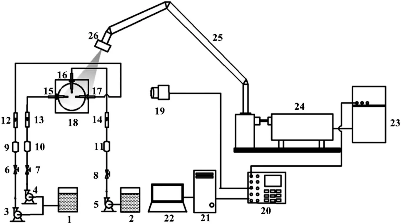
Fig.1.Schematic diagram of the apparatus used to measure flow characteristics using PIV.1,2—reservoir;3,4,5—pump;6,7,8—valve;9,10,11—buffer tube;12,13,14—rotameter;15,16,17—inlet channel;18—plexiglas plate;19—CCD camera;20—synchronous controller;21—image acquisition workstation;22—monitor and software interface;23—laser controller;24—pulse laser;25—light arm;26—optical parts.
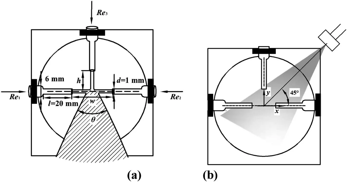
Fig.2.The structure and laser plane of FTIJs.
2.3.Re and TKE
Re of each jet is defined by the kinematic viscosity of water,ν,the mean velocity through the jet,ui,and d,as

where Viis the volumetric flow rate of jet i.
In general,turbulence on the large scale is anisotropic.Nevertheless,Pope[20]proposed that at high Re,the geometry of the large scales is lost in the chaotic scale-reduction process,by which energy is transferred to successively smaller and smaller scales,and these smaller scales are nearly isotropic.The mean turbulence dissipation rate of a confined planar-jet reactor was estimated in homogeneous and isotropic turbulence by Feng et al.[29].Thus,the isotropic assumption was used in this work.
The velocity perpendicular to the measurement plane could not be directly measured using the 2D PIV system.Therefore,the TKE can be reasonably estimated in the x–y plane using an isotropic assumption from[22,30–34]

2.4.Operational conditions
The operational conditions used in this study are listed in Table 1.The experiments were divided into four sets.In Set 1,the effect of Rewas investigated on the velocity distributions in FTIJs.A rule was developed for how the jet spacing influenced flow.In Sets 2–4,velocity and TKE distributions were evaluated at different jet spacings.d is the inner diameter of jet in Table 1,wis the distance between the horizontal coaxial jet exits along the x-axis,and h is the distance of the 3rd jet perpendicular to the horizontal axis(h)in Fig.2(a).The volumetric flow rates were set at V1=V2=V3for all experiments,so that Re1,Re2,and Re3are the same value,as Fig.2(a)shown respectively.The volumetric flow rate ratio,which was defined as V3/(V1+V2),was always 0.5 for all experiments.Moreover,we use the expansion angle to describe the variations of velocity distribution below the horizontal axis by the collision of three liquid jets shown in Fig.2(a).

Table 1 Experimental operating conditions for the FTIJs.
3.Results and Discussion
3.1.Effect of Re on the instantaneous velocity field
Generally,a larger jet velocity results in a larger expansion angle,which promotes liquid development and breakup,causes the liquid to become more unstable and more turbulent,and intensifies the mixing process[35].Fig.3 shows the instantaneous velocity distributions atdifferent jet velocities and Re.The red regions have higher velocities(u/u0>0.9),and the blue regions have lower velocities(u/u0<0.3).
As Re increases,different velocity distributions are observed.When Re is low[Fig.3(a)–(c)],the velocity is mainly distributed at y < 0 mm.The expansion angle is small,<60°,because the jet velocity is relatively low at Re=1500,implying weak turbulence in liquid.When Re increases[Fig.3(d)–(f)],a small number of velocity distributions appear above the horizontal axis.Below the horizontal axis,the expansion angle increases to >90°.The higher jet velocity at Re=2500 causes faster liquid motion and more turbulence.When Re is increased further[Fig.3(g)–(i)],the velocity distributions of liquid spread throughout entire measurement region.Higher velocities indicate much faster liquid motion and high kinetic energy.The expansion angle reaches nearly 180°,as abovementioned,causing the liquid to become more unstable and greater turbulence.Therefore,increasing Re leads to a larger expansion angle,and intensifies the turbulent liquid.
3.2.Effect of Re on the mean velocity field

Fig.3.The instantaneous velocity vectors in the x–y plane of FTIJs.(a)–(c)Re=1500,(d)–(f)Re=2500,and(g)–(i)Re=4100.
The variations of velocity distribution are more visible in the mean velocity field at different Re as Fig.4 shown.When Re=1500[Fig.4(a)],the streamlines indicate that the liquid mainly flows downstream.Low velocities lead to a small and symmetric expansion angle relative to y-axis,causing relatively stable motion of liquid below the horizontal axis.As Re increases,an increasing of jet velocity increases the expansion angle,so that the liquid turbulence is intensified.The streamlines above the horizontal axis imply that the liquid flow behavior has changed from flowing downstream to radially outward from the impingement zone.These results are in agreement with the instantaneous velocity distributions as Fig.3 shown.Especially,at Re=4100[Fig.4(c)],the velocity distributions spread throughout the entire measurement region,and the expansion angle approaches to 180°,performing stronger turbulence of liquid.Therefore,in the following sections,Re=4100 was used to study turbulent behaviors at different jet spacings.
3.3.Effect of jet spacing on the instantaneous velocity field
The instantaneous velocity fields are shown in Fig.5 for the three jet spacings(w/d=10,h/d=10;w/d=20,h/d=10;and w/d=20,h/d=20)at Re=4100.In each case,the liquid streams entering from the three sides are clearly visible.
These instantaneous velocity distributions in Fig.5 do not show much difference on liquid flow behavior that the liquid flows radially from the impingement zone.Faster liquid motion and large expansion angles are achieved than at Re of 1500 and 2500.This increased motion strongly perturbs the liquid than Re=1500 or 2500.However,the expansion angle decreases as the jet spacing is increased.As discussed above,the liquid becomes less turbulent,poor momentum transfer and mixing was resulted.
At the smallest jet spacing[Fig.4(a)–(c)],the rapid flow rate of the incoming liquid and the small distance between the jets increase the liquid velocity and the expansion angle,causing more turbulent liquid.In contrast,for w/d=20 and h/d=10[Fig.4(d)–(f)],the relatively large jet spacing causes the velocities to decrease.Therefore,the liquid which requires fast motion,becomes smaller and less turbulent.However,when w/d=20 and h/d=20[Fig.4(h)–(i)],an obvious decrease in velocity is not observed,but the expansion angle further decreases,leading to the formation of a less turbulent liquid.

Fig.4.The mean velocity vector maps in the x–y plane of FTIJs.(a)Re=1500;(b)Re=2500;and(c)Re=4100.
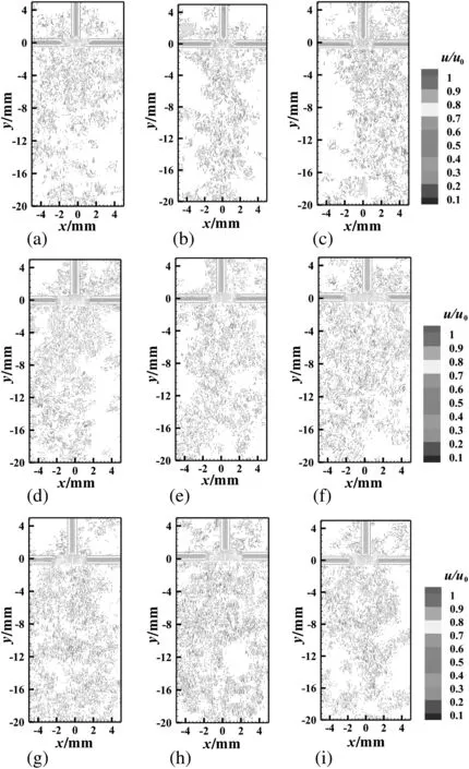
Fig.5.The instantaneous velocity vectors in the x–y planes of FTIJs.(a)–(c)w/d=10,h/d=10;(d)–(f)w/d=20,h/d=10;and(g)–(i)w/d=20,h/d=20.
3.4.Effect of jet spacing on the mean velocity field
The mean velocities in FTIJs with different jet spacings are shown in Fig.6.The streamlines indicate that the liquid flows radially outwards from the impingement zone,and independent of jet spacing.As the jet spacing increases,the expansion angle significantly decreases in size,and the velocity magnitude decreases especially at y>0 mm,resulting in less turbulent liquid.For w/d=20 and h/d=20,the liquid needs a greater Re or higher velocity to attain the similar expansion angle and turbulence degree as w/d=10 and h/d=10.
Two stagnation points are visible where the velocity magnitude approaches zero from the enlarged plots of the impingement zone in Fig.6(d)–(f),and Fig.7 shows that the stagnation points(i.e.,points where the velocity is near zero),which are statistically retrieved,are located in the ranges of-0.2<2Δx/w<-0.1 and 0.1<2Δx/w<0.2,where Δx is the distance off from the center along the x-axis.Increasing the jet spacing does not change the profiles of mean velocity at y=0 mm.The mean velocity magnitude sharply decreases to their minimum values when 2Δx/w is increased from-0.3 to-0.2,before increasing from 2Δx/w=-0.2 to 0.Similar behavior is observed for the other half of the x axis.Therefore,W-shaped profiles are observed at y=0 mm in the x–y plane(Fig.7).The two stagnation points are slightly asymmetrical,because it is difficult to perfectly balance the flows in the three jets using the pumps but this deviation of the location of stagnation points is about 3%in all experiments.
3.5.Profiles of the x-component of the mean velocity
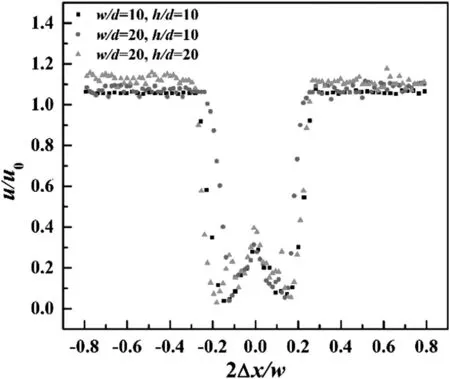
Fig.7.Mean velocity profiles at y=0 mm in the x–y plane for the three different jet spacings(u0=4.1 m·s-1).
Since the velocity distribution is closely related to the direction of motion and the kinetic energy of the droplets disintegrated from the liquid,it plays an important role in the analytical modeling of liquid disintegration[35,36].Fig.8 shows the profiles of the x-component of the mean velocity(ux)at Re=4100.The data is reported from 2Δx/w=-1.0 to 1.0,covering the entire distance between the two horizontal jets along the x-axis,along which the liquid is ejected from two nozzles.These two streams collide with the perpendicular jet between-0.2<2Δx/w<-0.1 and 0.1<2Δx/w<0.2,causing the formation of two stagnation points at approximately 2Δx/w=-0.15 and 2Δx/w=0.15.However,the results indicate that the velocity is actually non-zero in the range-0.15 < 2Δx/w<0.15,perhaps because of complex inelastic collisions between liquid streams originating between the perpendicular jet and the two horizontal jets.
Fig.9 shows the x-component of the mean velocity measured at x=0 mm,±1 mm,±2 mm,and±3 mm at Re=4100 for the three different jet spacings studied.In all cases,at-0.2<2Δy/h<0.2,is approximately zero at x=0 mm,is negative for x>0 mm,and is positive at x<0 mm.
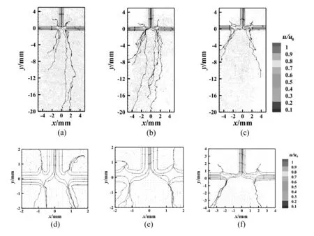
Fig.6.The mean velocity vector in the x–y plane of FTIJs.(a),(d)w/d=10,h/d=10;(b),(e)w/d=20,h/d=10;and(c),(f)w/d=20,h/d=20.
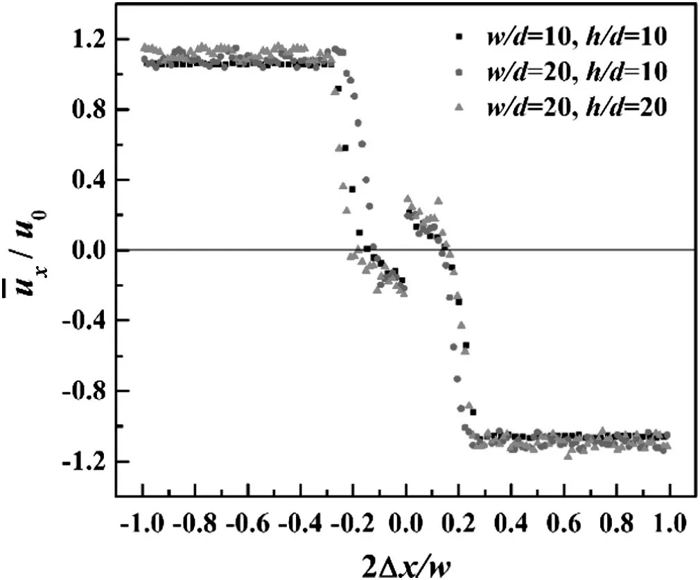
Fig.8.Profiles of the x-component of the mean velocity at y=0 mm in the x–y plane for the three different jet spacings.
For w/d=10 and h/d=10[Fig.9(a)],is mostly non-zero and irregularly distributed throughout.Similardistributions at 2Δy/h<0.2 are observed at w/d=20 and h/d=10[Fig.9(b)],butsharply decreases at 2Δy/h>0.2.It implies lower liquid motion and less turbulence appear at y>0 mm.Atthe largest jet spacing under the present operating parameters[Fig.9(c)],lots ofapproach zero at2Δy/h>0.2,causing a further decrease in the liquid turbulence at y>0 mm.
3.6.Profiles of the y-component of the mean velocity
The profiles of the y-component of the mean velocityat y=0 mm,±0.5 mm,±1 mm,and ±4 mm along the x-axis are plotted in Fig.reaches its maximum value near 2Δx/w=0 at y≥1 mm.In all cases,mostis positive at y>0.5 mm ranging from-0.4<2Δx/w <-0.1 and 0.1<2Δx/w <0.4,causing the liquid flows radially outward from the impingement zone.
In Fig.10(a),is higher and more irregularly distributed,indicating a strongly turbulent liquid.In Fig.10(b)vs.Fig.10(a),increasing jet spacing decreases the magnitude ofat y>0 mm.Combining the xcomponent velocity distributions in Fig.9(b),the liquid,accordingly,becomes less turbulent above the horizontal axis.As the jet spacing further increases in Fig.9(c),negative values ofindicate that most liquid is more likely to flow downstream.approaches zero at 2Δx/w>0.4 and 2Δx/w<-0.4,because of small expansion angles.As mentioned above,small expansion angles produce less turbulence.The results show the agreement with the velocity distributions and variations of expansion angles in Fig.4.
Fig.11 shows profiles of the y-component of the mean velocity at x=0 mm for the three jet spacings.A relatively stable liquid motion is produced along the perpendicular jets at 2Δy/h>0.2 and x=0 mm.
Overall,increasing the jet spacing causes lower velocities and less kinetic energy,especially the sharply decreasing of the velocity distribution at y>0 mm.Meanwhile,the expansion angle decreases significantly.These effects possibly result in less turbulence and poorer mixing.
3.7.TKE distributions

Fig.9.Profiles of the x-component of the mean velocity at x=0 mm,±1 mm,±2 mm,and±3 mm for(a)w/d=10,h/d=10;(b)w/d=20,h/d=10;and(c)w/d=20,h/d=20.

Fig.10.Profiles of the y-component of the mean velocity at y=0 mm,±0.5 mm,±1 mm,and±4 mm for(a)w/d=10,h/d=10;(b)w/d=20,h/d=10;and(c)w/d=20,h/d=20.
Fig.12 shows the TKE distributions in the x–y plane of the FTIJs with the three different jet spacings at Re=4100.Two high TKE regions are observed with peak values located at the stagnation points,resulting in an inverted W-shaped TKE profiles as shown in Fig.13.The collision of the liquid streams from the closely spaced jets caused a large velocity gradient to develop,resulting in intense turbulence and a large region in the impingement zone with a high TKE.This high TKE region is more expanded at w/d=10 and h/d=10 compared to that observed at w/d=20 and h/d=20.Meanwhile,when the jet spacing is increased(Fig.12),the larger region withindicates less turbulent.Therefore,a large jet spacing needs a higher velocity or Re to obtain the similar liquid turbulence as a small jet spacing.These TKE distributions are in good agreement with the previous observation that a decrease in the jet spacing intensifies the turbulence[37].
In the impingement zone,the mean velocity magnitudes decrease sharply and approach zero at the two stagnation points(Fig.6).However,TKE values sharply increase in these regions with peak values located at the two stagnation points,showing the opposite behavior of the TKE distribution profiles in the x–y plane in Fig.13 compared with the mean velocity profiles in Fig.7.TKE distributions are independent of the jet spacing,and the peak values only slightly decrease as the jet spacing increases.This increased turbulence in the impingement zone suggests that the FTIJs are suitable for rapid chemical reactions at unequal volumetric flow rat ratios.The present work enables the optimization of the geometric parameters of the FTIJs,which should be useful for the designing of FTIJs to obtain the expected turbulence degree.
Because of simple structure,excellent atomization,and intensive mixing of FIJRs,they are commonly used in many fields including liquid propellant rocket engines and clathrate formation in energy technology.A “wall-free”environment causes FIJRs to receive more attention in sol–gel processes and reactors for various chemical engineering processes[1,3,35].As mentioned above,under the condition of unequal flow rate ratio,the impingement plane deviated from the center between the opposed jets and shifted towards to the lower momentum jet by using the impinging jet reactor of two nozzles,resulting in poor mixing efficiency[22].The FTIJs were designed to improve mixing quality for the rapid liquid–liquid reactions at unequal volumetric flow rate ratios,such as rapid precipitation reactions.The experimental results show that the flow characteristics of FTIJs are different from that of two jets collided.As a consequence,a further investigation of mixing by using PLIF enables us to understand better the mixing mechanism in FTIJs.
4.Conclusions
Novel FTIJs are developed to improve the liquid–liquid mixing efficiency for rapid chemical reactions at unequal volumetric flow rate ratios.The flow characteristics were investigated using PIV to measure the instantaneous velocity,the mean velocity,and TKE distributions.The study of instantaneous velocity at different Re values provides the velocity variations in FTIJs.When two jets are coaxial collided,axial velocity becomes zero and converts into radial velocity.However,as Re increases from 1500 to 4100,the streamlines indicate that the liquid flows from downstream to radially outward from the impingement zone.The turbulent nature of the flow remains relatively constant when the jet spacing is increased at Re=4100.In order to understand the effect of the geometric parameters on the flow field,the instantaneous velocities,the mean velocities,the profiles of the x-and y-components of the mean velocities,and the TKE distributions were discussed for three different jet spacings at Re=4100 with a volumetric flow rate ratio of 0.5.Increasing jet spacing has no influence on the positions of the stagnation points,which are located in the ranges of-0.2<2Δx/w<-0.1 and 0.1<2Δx/w <0.2,where TKE is at its maximum values in these regions.Nevertheless,increasing jet spacing causes the expansion angles and TKE to decrease in FTIJs,a large jet spacing needs a higher velocity or Re to obtain the similar expansion angle and liquid turbulence as a small jet spacing.The present work enables the optimization of the geometric parameters of the FTIJs,which should be useful for the designing of FTIJs to obtain the expected turbulence degree and mixing efficiency.

Fig.11.Pro files of the y-componentof the mean velocity at x=0 mm for the three different jet spacings.

Fig.13.TKE profiles at y=0 mm in the x–y plane for the three different jet spacings.

Fig.12.TKE distributions in the x–y plane of FTIJs at Re=4100.(a)w/d=10,h/d=10;(b)w/d=20,h/d=10;and(c)w/d=20,h/d=20.

[1]P.Erni,A.Elabbadi,Free impinging jet microreactors:controlling reactive flows via surface tension and fluid viscoelasticity,Langmuir 29(2013)7812–7824.
[2]B.K.Johnson,R.K.Prudˊhomme,Chemical processing and micromixing in confined impinging jets,AICHE J.49(2003)2264–2282.
[3]D.V.R.Kumar,B.L.V.Prasad,A.A.Kulkarni,Impinging jet micromixer for flow synthesis of nanocrystalline MgO:Role of mixing/impingement zone,Ind.Eng.Chem.Res.52(2013)17376–17382.
[4]I.Valente,E.Celaco,D.L.Marchisio,A.A.Barresi,Nanoprecipitation in confined impinging jets mixers:Production,characterization and scale-up of pegylated nanospheres and nanocapsules for pharmaceutical use,Chem.Eng.Sci.77(2012)217–227.
[5]A.M.Dehkordi,A novel two-impinging-jets reactors for copper extraction and stripping processes,Chem.Eng.J.87(2002)227–238.
[6]S.M.Hosseinalipour,A.S.Mujumdar,Superheated steam drying of a single particle in an impinging stream dryer,Dry.Technol.13(1995)1279–1303.
[7]J.L.Lapčik,M.Fraštik,B.Lapčikova,Impinging jet study of the deposition of colloidal particles on modified polycarbonate and poly(ethylene terephthalate)surfaces,Int.J.Heat Mass Transf.55(2012)1513–1518.
[8]J.Eggers,E.Villermaux,Physics of liquid jets,Rep.Prog.Phys.71(2008)036601.
[9]E.Villermaux,Fragmentation,Annu.Rev.Fluid Mech.39(2007)419.
[10]S.W.Siddiqui,Y.Zhao,A.Kukukova,S.M.Kresta,Characteristics of a confined impinging jet reactor:Energy dissipation,homogeneous and heterogeneous reaction products,and effect of unequal flow,Ind.Eng.Chem.Res.48(2009)7945–7958.
[11]R.J.Santos,E.Erkoc,M.M.Dias,A.M.Teixeira,J.C.B.Lopes,Hydrodynamics of the mixing chamber in RIM:PIV flow- field characterization,AICHE J.54(2008)1153–1163.
[12]M.Icardi,E.Gavi,D.L.Marchisio,A.A.Barresi,M.G.Olsen,R.O.Fox,D.Lakehal,Investigation of the flow field in a three dimensional confined impinging jets reactor by means of microPIV and DNS,Chem.Eng.J.166(2011)294–305.
[13]Y.Liu,M.G.Olsen,R.O.Fox,Turbulence in a microscale planar confined impingingjets reactor,Lab Chip 9(2009)1110–1118.
[14]Y.Liu,R.O.Fox,CFD predictions for chemical processing in a confined impinging-jets reactor,AICHE J.52(2006)731–744.
[15]Y.X.Shi,V.Somashekar,R.O.Fox,M.G.Olsen,Visualization of turbulent reactive mixing in a planar microscale confined impinging-jet reactor,J.Micromech.Microeng.21(2011)115006.
[16]S.J.Jung,S.D.Hoath,G.D.Martin,I.M.Hutchings,Atomization patterns produced by the oblique collision of two Newtonian liquid jets,Phys.Fluids 22(2010)042101.
[17]R.Li,N.Ashgriz,Characteristics of liquid sheets formed by two impinging jets,Phys.Fluids 18(2006)087104.
[18]G.Taylor,The dynamics of thin sheets of fluid.III.Disintegration of fluid sheets,Proc.R.Soc.Lond.A Math.Phys.Eng.Sci.253(1959)313–321.
[19]R.J.Demyanovich,J.R.Bourne,Rapid micromixing by the impingement of thin liquid sheets.2.mixing study,Am.Chem.Soc.28(1989)830–839.
[20]S.B.Pope,Turbulent flows,Cambridge University Press,Cambridge,2000.
[21]C.P.Fronte,M.A.Sultan,R.J.Santos,M.M.Dias,J.C.B.Lopes,Flow imbalance and Reynolds number impact on mixing in confined impinging jets,Chem.Eng.J.260(2015)316–330.
[22]Z.M.Gao,J.Han,Y.D.Xu,Y.Y.Bao,Z.P.Li,Particle image velocimetry(PIV)investigation of flow characteristics in confined impinging jet reactors,Ind.Eng.Chem.Res.52(2013)11779–11786.
[23]R.P.Lindstedt,D.S.Luff,J.H.Whitelaw,Velocity and strain-rate characteristics of opposed isothermal flows,Flow Turbul.Combust.74(2005)169–194.
[24]J.W.M.Bush,A.E.Hasha,On the collision of laminar jets:Fluid chains and fishbones,J.Fluid Mech.511(2004)285–310.
[25]A.J.Mahajan,D.J.Kirwan,Micromixing effects in a two-impinging-jets precipitator,AICHE J.42(1996)1801–1814.
[26]W.F.Li,Z.G.Sun,H.F.Liu,F.C.Wang,Z.H.Yu,Experimental and numerical study on stagnation point offset of turbulent opposed jets,Chem.Eng.J.138(2008)283–294.
[27]W.F.Li,T.L.Yao,F.C.Wang,Study on factors influencing stagnation point offset of turbulent opposed jets,AICHE J.56(2010)2513–2522.
[28]D.A.Johnson,Experimental and numerical examination of confined laminar opposed jets.Part I.Momentum imbalance,Heat Mass Transf.27(2000)444–453.
[29]H.Feng,M.G.Olsen,Y.Liu,R.O.Fox,J.C.Hill,Investigation of turbulent mixing in a confined planar-jet reactor,AICHE J.51(2005)2649–2664.
[30]R.O.Fox,Computational models for turbulent reacting flows,Cambridge University Press,Cambridge,2003 35–39.
[31]E.Gavi,D.L.Marchisio,A.A.Barresi,M.G.Olsen,R.O.Fox,Turbulent precipitation in micromixers:CFD simulation and flow field validation,Chem.Eng.Res.Des.88(2010)1182–1193.
[32]F.R.Khan,C.D.Rielly,D.A.R.Brown,Angle-resolved stereo-PIV measurements close to a down-pumping pitched-blade turbine,Chem.Eng.Sci.61(2006)2799–2806.
[33]J.Sheng,H.Meng,R.O.Fox,A large eddy PIV method for turbulence dissipation rate estimation,Chem.Eng.Sci.55(2000)4423–4434.
[34]Z.P.Li,M.T.Hu,Y.Y.Bao,Z.M.Gao,Particle image velocimetry experiments and large eddy simulations of merging flow characteristics in dual Rushton turbine stirred tanks,Ind.Eng.Chem.Res.51(2012)2438–2450.
[35]F.Q.Bai,H.Diao,M.Z.Zhang,Q.Chang,E.D.Wang,Q.Du,Breakup characteristics of power-law liquid sheets formed by two impinging jets,Fluid Dyn.Res.46(2014)055506.
[36]Y.J.Choo,B.S.Kang,The velocity distribution of the liquid sheet formed by two lowspeed impinging jets,Phys.Fluids 14(2002)622–627.
[37]J.Zhang,Y.Z.Liu,W.Z.Jiao,G.S.Qi,Flow characteristics in a three impinging jets reactor,Chin.J.Process.Eng.15(2015)218–223(in Chinese).
 Chinese Journal of Chemical Engineering2016年6期
- Chinese Journal of Chemical Engineering的其它文章
- Mixture temperature prediction of waxy oil–water two-phase system flowing near wax appearance temperature☆
- Preparation and characterization of sulfated TiO2 with rhodium modification used in esterification reaction and decomposition of methyl orange☆
- Online process monitoring for complex systems with dynamic weighted principal component analysis☆
- A stepwise optimal design of water network☆
- Integration of coal pyrolysis process with iron ore reduction:Reduction behaviors of iron ore with benzene-containing coal pyrolysis gas as a reducing agent☆
- Multiple linear equation of pore structure and coal–oxygen diffusion on low temperature oxidation process of lignite☆
