Design and Control of Thermally Coupled Reactive Distillation Sequence for Biodiesel Production
Li Lumin; Sun Lanyi; Xie Xu; Tian Yanan; Shang Jianlong; Tian Yuanyu
(1. State Key Laboratory of Heavy Oil Processing, China University of Petroleum, Qingdao 266580; 2. SINOPEC Research Institute of Petroleum Processing, Beijing 100083)
Design and Control of Thermally Coupled Reactive Distillation Sequence for Biodiesel Production
Li Lumin1; Sun Lanyi1; Xie Xu1; Tian Yanan2; Shang Jianlong1; Tian Yuanyu1
(1. State Key Laboratory of Heavy Oil Processing, China University of Petroleum, Qingdao 266580; 2. SINOPEC Research Institute of Petroleum Processing, Beijing 100083)
Decreasing petroleum reserves and growing alternative fuels requirements have promoted the study of biodiesel production. In this work, two thermally coupled reactive distillation designs for biodiesel production were investigated, and the sensitivity analysis was conducted to obtain the appropriate design values. The thermodynamic analysis and economics evaluation were performed to estimate the superiority of the thermally coupled designs over the base case. The proposed biodiesel production processes were simulated using the simulator Aspen Plus, and calculation results show that the exergy loss and economic cost in the two thermally coupled designs can be greatly reduced. It is found that the thermally coupled side-stripper reactive distillation design provides more economic bene fi ts than the side-recti fi er one. The dynamic performance of the thermally coupled side-stripper design was investigated and the results showed that the proposed control structure could effectively handle large feed disturbances.
thermally coupled reactive distillation; biodiesel production; thermodynamic analysis; total annual cost; control
1 Introduction
When considering the petroleum supplies and their great impact on the environmental consequences, the technology development of renewable energy is becoming more and more urgent. As an alternative source of fossil fuels, biodiesel plays an important role in the modern energy revolution. Biodiesel is a kind of safe, renewable, non-toxic and biodegradable fuel, and it has been rapidly attracting an increased interest in many countries[1-3]. The conventional biodiesel manufacturing technology comprises separation and reaction processes, including a series of distillation processes to purify the desired products and recover the unreacted raw materials, which cover a range of energy-intensive industrial processes. The methods of biodiesel synthesis mainly include the trans-esterification and esterification reactions, and all these methods suffer from problems associated with the use of homogeneous catalysts, leading to a costly separation procedure[4].
Florin Omota, et al.[5-6]proposed that it was feasible to use reactive distillation for the synthesis of fatty esters, the major components of ‘bio-diesel’ fuels. Kiss, et al.[7]reported that biodiesel can be produced by a sustainable continuous process based on catalytic reactive distillation using metal oxide solid acid catalysts. Other reactive distillation processes such as dual reactive distillation[8], reactive stripping[9]and dividing-wall column[10-11]were recently proposed as the innovative processes for synthesis of fatty acid methyl esters (FAME) using solid acid catalysts.
Reactive distillation that integrates the reaction and separation processes into one column is an attractive alternative of process intensification method with lower capital and energy costs. However, the biodiesel production process based on reactive distillation mainly involves two columns, which include a reactive distillation column and a reactant recovery column, leading to a higher operation and capital cost[10-11]. In order to decrease the cost in biodiesel production, two thermally coupled reactive distillation processes are proposed in this paper.
2 Basic Reactive Distillation Process
FAME are usually produced from fat sources such as animal fats, vegetable oils or waste oils by (trans-) esterification with methanol[12]. In this work, the esterification of free fatty acids (FFA) with methanol is carried out in the presence of super acid solid catalyst. As a major component in coconut oil, lauric acid is used to represent FFA, and the kinetic data for the esteri fi cation is available from the work of Kiss, et al.[7-8,13]The Aspen Plus simulator is used to design the biodiesel production process. In addition, the activity coefficient model UNIQUAC is used to estimate the phase equilibrium in the reactive distillation column (RDC), and the activity coefficient model of NRTL is adopted for predicting the equilibrium and liquid properties in the methanol recovery column (MRC)[14].
As shown in Figure 1, lauric acid and methanol at 25 ℃are preheated and then fed in the RDC. Methyl laurate with a purity of 99.4% is obtained at the bottom of RDC, which is then used to heat the feed streams. The distillate containing methanol and the by-product water is fed into MRC to recycle the unreacted methanol. The waste water, which accounts for 99 percent by mass of total ef fl uent, is discharged from the bottom of MRC.
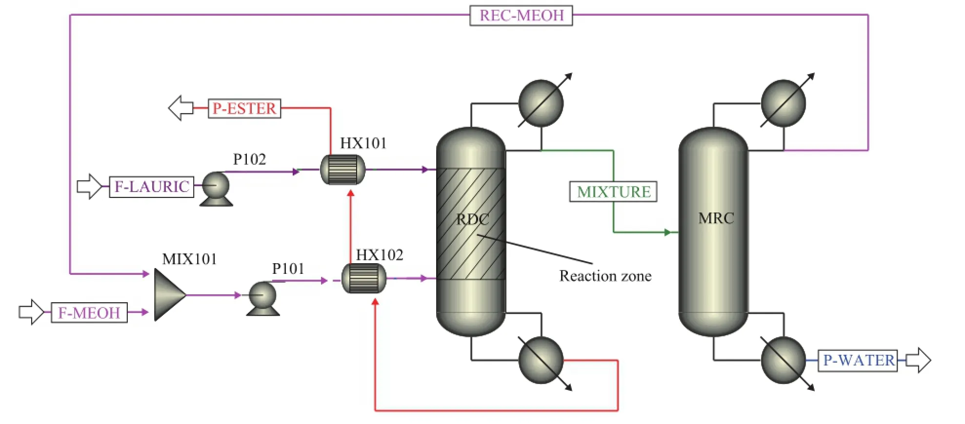
Figure 1 Basic fl owsheet of reactive distillation for biodiesel production implemented by Aspen Plus

Figure 2 Temperature versus composition for lauric acid-methanol (left) and methyl laurate-methanol (right) systems
The vapor-liquid equilibrium diagrams (lauric acidmethanol; methyl laurate-methanol) under different pressures are obtained using sensitivity analysis tool in the Aspen Plus (see Figure 2). It can be seen that at a certain mole fraction of lauric acid or methyl laurate, the temperature tends to be higher as the pressure increases. As the liquid mole fraction of lauric acid or methyl laurate increases from 0.9 to 1, the correspondingtemperature changes rapidly. Therefore, in order to avoid the high temperature at the bottom of RDC, which will adversely affect the quality of biodiesel (because of pyrolysis, and other reactions), it is usually taken out to ensure that the methyl laurate purity in the reboiler of RDC is around 95% mole fraction. In this study the bottom rate in the RDC is 104 kmol/h when the conversion of lauric acid achieves 99.99%. It should be noted that the feed conditions and product speci fi cations of this basic flowsheet are consistent with those of the thermally coupled reactive distillation processes for fair comparison.
3 Thermally Coupled Side-Rectifier Reactive Distillation (TCSR-RD) in Biodiesel Production
Figure 3 shows three thermally coupled con fi gurations (side-rectifier, side-stripper, Petlyuk) which can be applied in the biodiesel production[14]. Among the three con fi gurations, the side-recti fi er and side-stripper configurations can partly decrease the equipment investment cost and utility cost by adding two thermal coupling streams, while the Petlyuk con fi guration can achieve a full heat-integration with four interconnecting streams. Kiss, et al.[10-11]proposed a novel biodiesel process based on a reactive dividing-wall column, and the novel design alternative allows a fortune to be saved by reducing the energy requirements by more than 25%. However, the total thermally coupled Petlyuk con fi guration has less widely used in industry as a result of its complicated operating conditions. Therefore, in this work we will discuss the application of the fi rst two con fi gurations in biodiesel production.

Figure 3 Thermally coupled reactive distillation con fi gurations for esteri fi cation of lauric acid with methanol
3.1 Steady-state simulation of the TCSR-RD
As shown in Figure 4, after being heated by the methyl laurate product, lauric acid is fed in the upper section of the RDC as a heavy component while methanol—in the lower section. Unlike the conventional reactive distillation process, the MRC operates without reboiler in the thermally coupled side-recti fi er reactive distillation (TCSR-RD) design. The vapor withdrawal from RDC is fed into MRC rather than from the reboiler in the classical case, leading to intensification of separation process. There is only one reboiler needed in the TCSRRD design, which can signi fi cantly reduce the energy requirements. To ensure the product purity, the theoretical stages in RDC will be increased. The major stream information of this TCSR-RD design is given in Table 1.
3.2 Sensitivity analysis of the TCSR-RD design
3.2.1 Feed location of the methanol stream
The sensitivity analysis of methanol feed stage on methyl laurate purity and reboiler duty is carried out and the results are shown in Figure 5. It should be noted that in Aspen Plus the stages are numbered starting from the condenser as stage 1 and ending with the reboiler as the last stage. When the feed position moves downward, the methyl laurate purity decreases and inversely the operating load increases. Therefore the methanol feed stage should be as high as possible in order to ensure the product quality.
3.2.2 Re fl ux ratio in the RDC
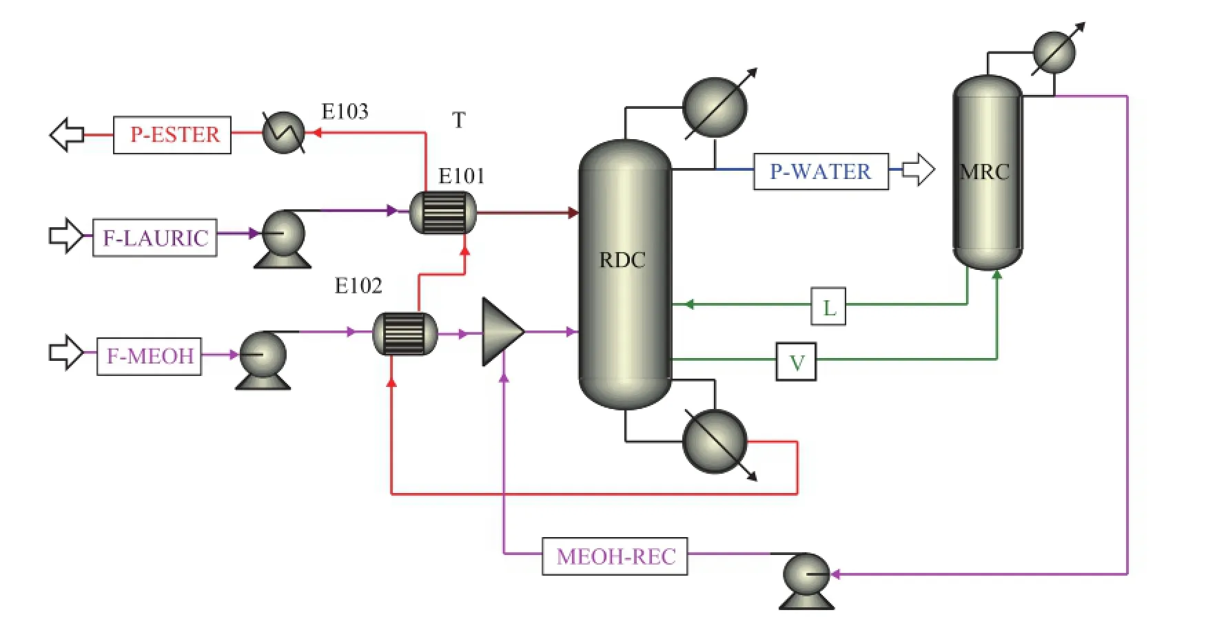
Figure 4 Thermally coupled side-recti fi er reactive distillation for biodiesel production

Table 1 Major stream information in the TCSR-RD design
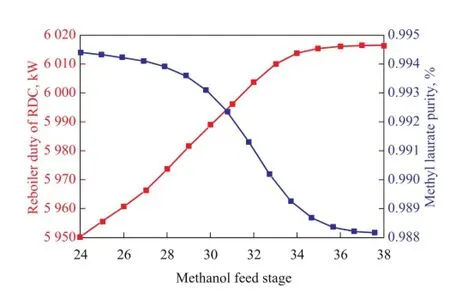
Figure 5 Sensitivity analysis of methanol feed stage on methyl laurate purity and reboiler duty
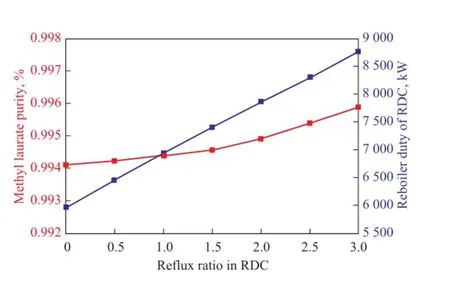
Figure 6 In fl uence of the re fl ux ratio in RDC on the purity of main products and reboiler duty
Figure 6 demonstrates the influence of reflux ratio in RDC on the purity of methyl laurate and the reboiler duty. It is shown that with the increase in the re fl ux ratio,the reboiler duty increases, and the product purity of methyl laurate follows a similar trend, which is always maintained at above 99.4%. Therefore, the reflux ratio will be chosen as small as possible in the simulation.
3.2.3 Flow rate of the vapor withdrawal
Figure 7 presents the effects of the withdrawn vapor fl ow rate on the recycled methanol product purity and reboiler duty. As shown in Figure 7, the reboiler duty in RDC increases greatly as more vapor stream is withdrawn. When more vapor stream is fed into MRC to promote the methanol-water separation, more liquid stream will be obtained at the bottom of MRC. It means that there will be more liquid flow that would return to RDC bottom, leading to a higher reboiler duty. The methanol purity in the recycle stream keeps an upward trend as the vapor withdrawal increases. However, the mass fraction of methanol remains stable when the flow rate of vapor withdrawal is more than 200 kmol/h.
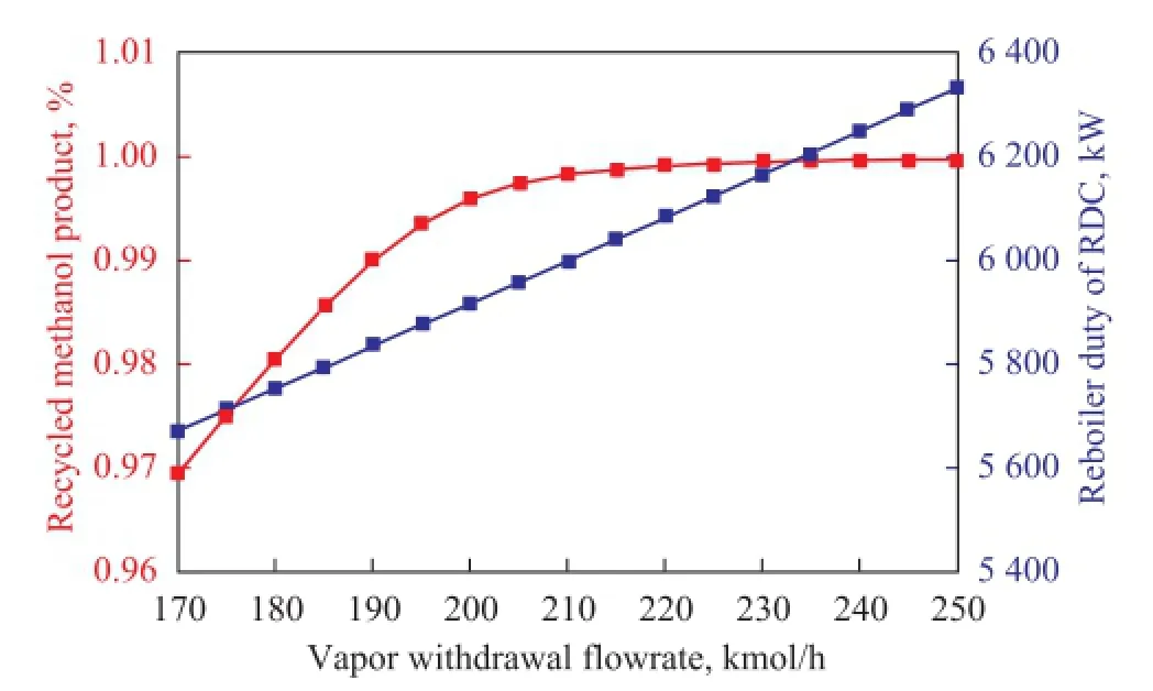
Figure 7 Effects of the vapor withdrawal fl ow rate on the recycled methanol product purity and reboiler duty
3.2.4 Vapor withdrawal location of the RDC
Figure 8 shows how the location of vapor withdrawal in the RDC affects the product purity and reboiler duty when other parameters are kept unchanged. The water content changes little while the withdrawal location varies. Moreover, the recycled methanol purity is always above 99.7%, and it can stabilize at a high level when the withdrawal stage location is less than or equals to 36. On the other hand, the plots of the reboiler duty and methyl laurate purity show a turning point at the stages 28 and 29, respectively, predominantly because the methanol feed stage is 28. When the vapor stream is withdrawn from the same stage, i.e., stage 28, the methanol feed will affect the purity of the withdrawn stream. The esterification is eventually hindered and thereby the operating duty increases. Thus, the withdrawal location should be away from the methanol feed stage and below the reaction zone to avoid the adverse impacts. Similarly, the location of liquid feed returning from the MRC should also be kept away from the reaction zone and the methanol feed position, and it will be consistent with the vapor withdrawal location.
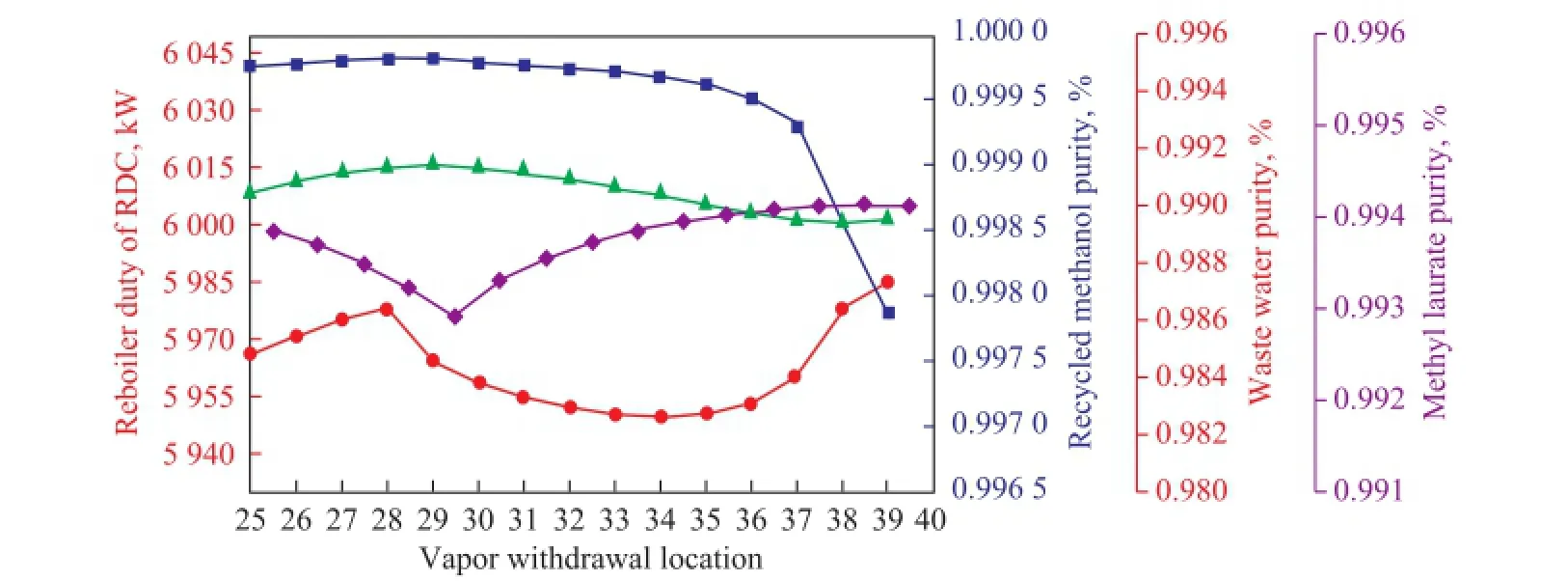
Figure 8 Effects of the vapor withdrawal location on product purity and reboiler duty
4 Thermally Coupled Side-stripper Reactive Distillation (TCSS-RD) in Biodiesel Production
4.1 Steady-state simulation of the TCSS-RD
The thermally coupled side-stripper reactive distillation (TCSS-RD) design for biodiesel production is given in Figure 9. Compared with the conventional sequence, it can be seen that the condenser in RDC is removed and the re fl ux stream in RDC is replaced by a liquid that is withdrawn from MRC. The vapor distillate is directly fed into MRC to recover the unreacted methanol. To realize a further heat utilization, the bottom productdischarged from RDC which mainly contains methyl laurate is used to preheat the two feed streams. Table 2 shows the major stream information in the TCSS-RD process.
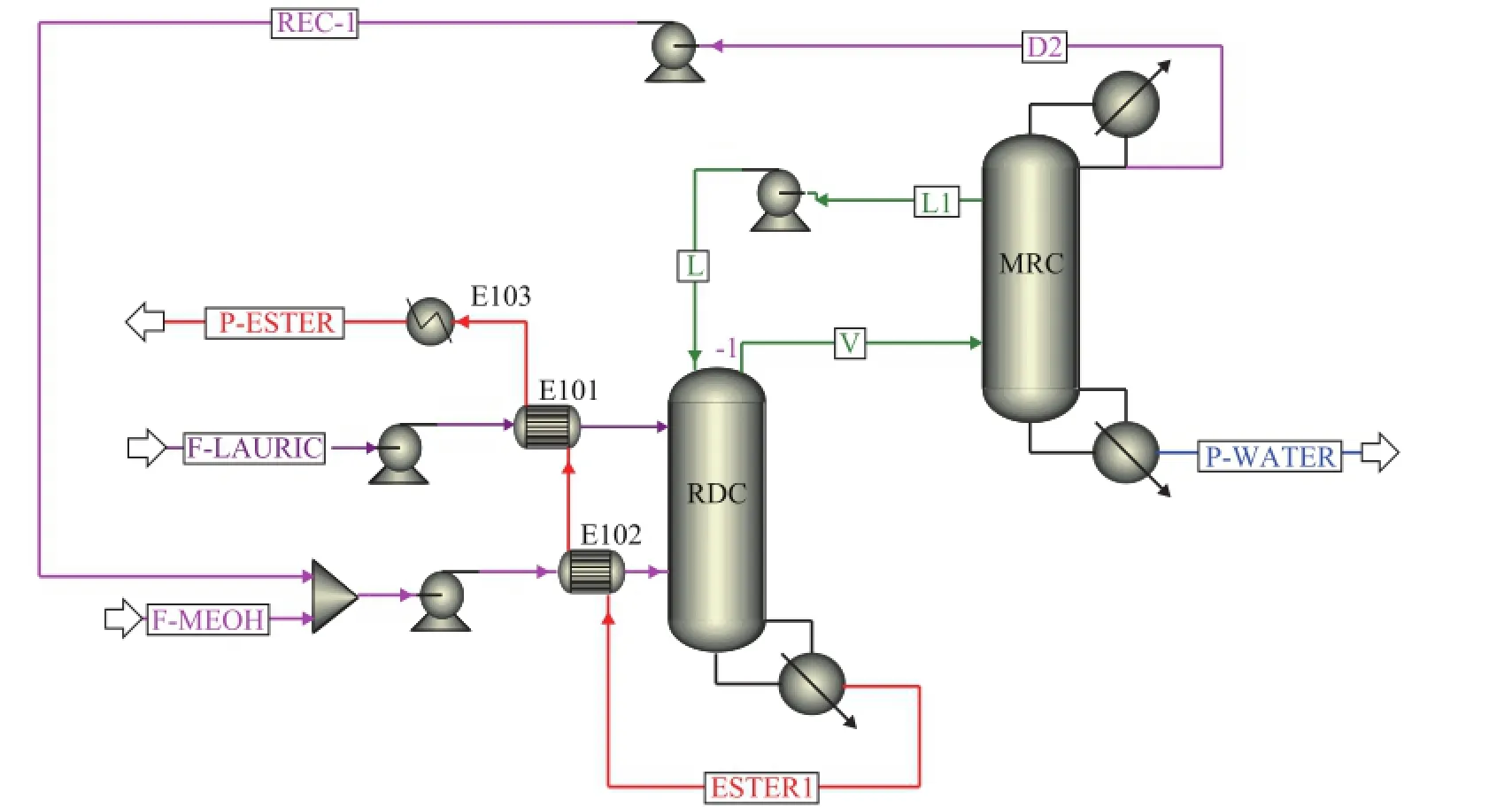
Figure 9 Thermally coupled side-stripper reactive distillation for biodiesel production

Table 2 Major stream information in the TCSS-RD desig
4.2 Sensitivity analysis of the TCSS-RD design
4.2.1 Feed location of vapor stream to MRC
The vapor feed stage to MRC is investigated as shown in Figure 10. When the vapor feed position in MRC moves downward, the energy requirement in MRC reduces, and the reboiler duty of RDC also shows a descending trend. The purity of methanol in recycled stream increases and eventually stabilizes at above 99.5% as the feed location moves down. This is because the lower feed position in MRC means the more stages available for distilling the mixture of methanol and water. Moreover, the increased methanol purity in the recycled stream is also a re fl ection of the better vapor-liquid contact in MRC. In order to maintain the methyl laurate purity at 99.4%, it is bene fi cial to choose a downward feed stage for MRC.
4.2.2 Re fl ux ratio in the MRC
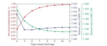
Figure 10 Sensitivity analysis of vapor stream feed stage on recycled methanol purity and reboiler duty
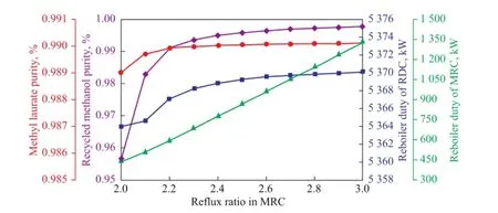
Figure 11 In fl uence of the re fl ux ratio in MRC on the product purity and reboiler duty
Figure 11 illustrates the in fl uence of re fl ux ratio in MRC on the product purity and reboiler duty. It is obvious that the purity of methyl laurate and methanol changes slightly when the re fl ux ratio is above 2.2. As shown in Figure 11, the increase of re fl ux ratio has little in fl uence on the reboiler duty of RDC, while the operating duty in MRC shows a continuously increasing trend. Therefore, the reflux ratio in MRC should be as small as possible, provided that the product has a desired purity.
4.2.3 Flow rate of the liquid withdrawal
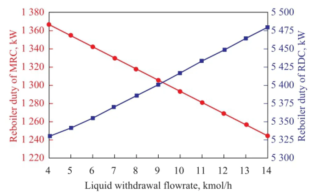
Figure 12 Effects of the liquid withdrawal fl ow rate on reboiler duty of RDC and MRC
Figure 12 shows how the fl ow rate of liquid withdrawal from MRC affects the reboiler duty of the two columns. As shown in Figure 12, the trend of heat duty in MRC is opposite to that found in RDC. As the mole flow of the side withdrawal increases, the reboiler duty in MRC decreases rapidly while that in RDC rises. For the case of RDC, the liquid withdrawal acts as the re fl ux. Therefore, the increase in the flow rate of liquid withdrawn from MRC definitely increases the reboiler duty of RDC. However, an increasing liquid withdrawal fl owrate from MRC leads to the decrease of liquid holdup in MRC. As a result, the operating duty of MRC declines when more liquid from MRC is being withdrawn.
The configurations and operating parameters for the two thermally coupled reactive distillation designs are presented in Table 3 to exhibit a direct comparison.
4.3 Comparison between different thermal designs
4.3.1 Composition pro fi les of reactive distillation column
The composition pro fi les of reactive distillation column in the two thermally coupled reactive distillation designs are shown in Figure 13. It is revealed that high-purity methyl laurate can be obtained in both TCSR-RD and TCSS-RD processes. In the TCSR-RD design, since there is a re fl ux liquid that is fed into RDC, the methanol concentration below the feed location is apparently higher than thatin TCSS-RD design, while the methanol content above the feed location is lower than that in TCSS-RD design, indicating to a certain influence of thermally coupled streams on the esteri fi cation reaction in RDC.

Table 3 Comparison of configurations and operating parameters between the base case and thermally coupled reactive distillation designs
4.3.2 Thermodynamic analysis
The minimum separation work (minimum exergy,Ex,min) can be calculated as the difference of exergies (ex) excluding the chemical exergy between the products and feed streams, which can be described as follows:

Exergy loss (Ex,loss) can be written as:

wherenis the mole flow;Qis the heat;WSis the shaft work;TOandTSare the surrounding and the system temperatures, respectively[15-16].
Thermodynamic efficiency (η) is the ratio of minimum separation work and total exergy input as shown below:

As the exergy loss exists in every irreversible process, the thermodynamic ef fi ciency is always between 0 and 1. In conventional distillation column, energy is used to heat the reboiler, and then the condenser releases some energy. Thus the thermodynamic efficiency is usually less than 1. According to the above equations, the exergy loss and thermodynamic ef fi ciency for each column are estimated as shown in Table 4.
It can be seen that the exergy loss in TCSR-RD and TCSS-RD designs are 1 250.5 kW and 1 043.1 kW, respectively, while that in the basic reactive distillation process is 1 367.8 kW. As a result, the TCSR-RD design can effectively reduce the exergy loss by 8.6% and the exergy loss of the TCSS-RD design is reduced by 23.7%, as compared with that in the basic reactive distillation design.
4.3.3 Economic evaluation
In order to carry out the economic analysis of the original process and the thermally coupled processes, the total annual cost (TAC) of the proposed designs is calculated. The provided formulas and parameters are based on the Douglas method[17]. To simplify calculations, the operating time for a year is assumed to be 8 000 hours. The payback time is assumed to be 3 years. The Marshall and Swift cost index (M & S) is1 431.7[18], and the related utilities price is given in the work of Huang, et al.[19]
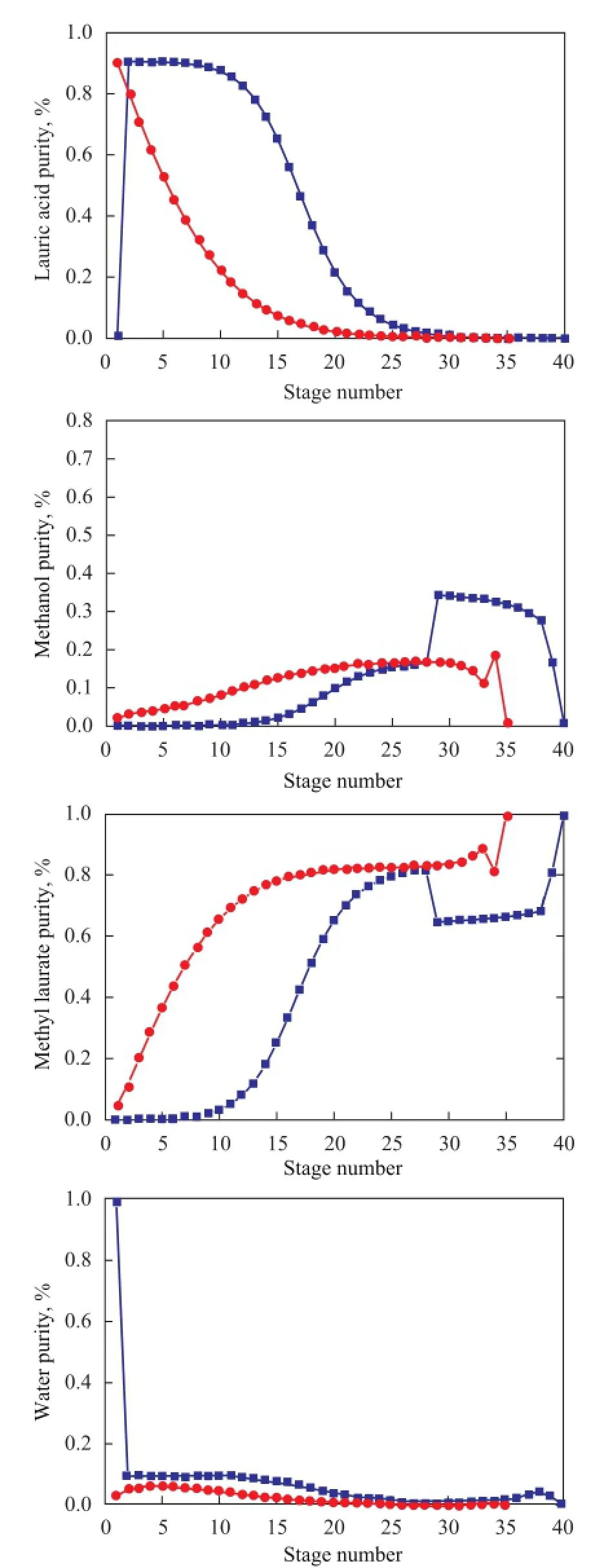
Figure 13 Composition pro fi les of reactive distillation column in TCSR-RD and TCSS-RD designs
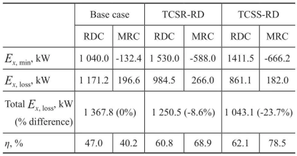
Table 4 Estimation of exergy loss and thermodynamic efficiency for each column
Table 5 shows the detailed calculation results of TAC. It is shown that, since only one condenser is used in the TCSS-RD design, the fixed investment cost is slightly reduced. In addition, the operating cost for the TCSSRD design is signi fi cantly reduced because of the thermal coupling between RDC and MRC. On the other hand, due to the high bottom temperature in RDC, the high-pressure steam should be used and the cost of high-pressure steam is a major part of the TAC[20]. Therefore, when the reboiler duty of TCSR-RD process increases, the operating cost is higher than that of the TCSS-RD design. However, the operating cost of TCSR-RD design is still lower than that of the conventional process. It is evident that the two thermally coupled designs are promising with the TACsavings amounting to 11.97% and 23.41% for the TCSRRD and the TCSS-RD designs, respectively.
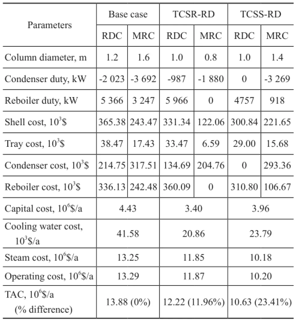
Table 5 Comparison of TAC between the base case, TCSR-RD and TCSS-RD designs
5 Plant-wide Control of the TCSS-RD Design
Since the TCSS-RD design shows a superior economic benefit, it is also interesting to study the dynamic performance of this TCSS-RD design. Therefore we will study the controllability of this TCSS-RD design in the following section. The detailed information about how to simulate a dynamic system is reported by Luyben[21], and Figure 14 presents a control structure.
The detailed control strategy is de fi ned as:
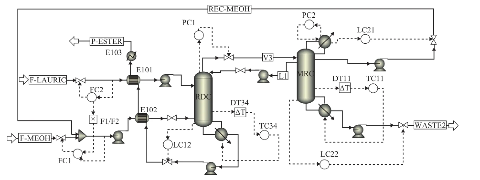
Figure 14 Control structure of the TCSS-RD design
(1) The fresh feed laurate acid to RDC is fl ow-controlled (reverse acting). The feed methanol flow rate is maintained at a constant ratio to the fl ow rate of laurate acid, and the flow controller of methanol is on cascade since its set-point signal is received from the F1/F2 ratio.
(2) The base level in each column is controlled by manipulating their corresponding bottom fl ow rate (direct acting).
(3) The reflux drum level in MRC is controlled by manipulating its corresponding distillate (direct acting).
(4) The pressure in RDC is controlled by manipulating the top vapor flow rate of RDC (direct acting), and the pressure in MRC is maintained by manipulating the corresponding condenser duty (reverse acting).
(5) The temperature on stage 34 of RDC is controlled using the TC34 controller by adjusting its reboiler heat input (reverse acting).
(6) The temperature of stage 11 in MRC is maintained using the TC11 controller by manipulating its reboiler duty (reverse acting).
The position of controlled tray temperature is chosen based on the temperature profile in each column where there is a large slope. Proportional controllers are adopted for the control of liquid levels, and other variables are controlled by the proportional-integral controllers. One minute dead time is inserted in each temperature controller. Relay-feedback tests are run and the Tyreus-Luyben tuning method is used to obtain the tuning parameters. For TC34 controller, the gainsKCand integral timeτ1are 17.33 and 6.60 min, respectively, and for TC11 controller, theKCandτ1are 7.59 and 7.92 min, respectively. The fresh feed laurate acid is adjusted by the throughput manipulator to test the simple singleend control structure, and the dynamic responses for this control structure are shown in Figure 15.
In Figure 15, the methanol flowrate is adjusted to keep the stoichiometric balance when the flowrate of laurate acid feed is changed. In addition, the controlled tray temperatures can settle down at their specified values after the fluctuations in feed flowrate, which reflects that the compositions in the corresponding stages can be maintained at their initial values through changing their reboiler duties. It is obvious that the product purity can be kept at their set-point values, which demonstrate that the simple PI control scheme presents a reasonable control performance.
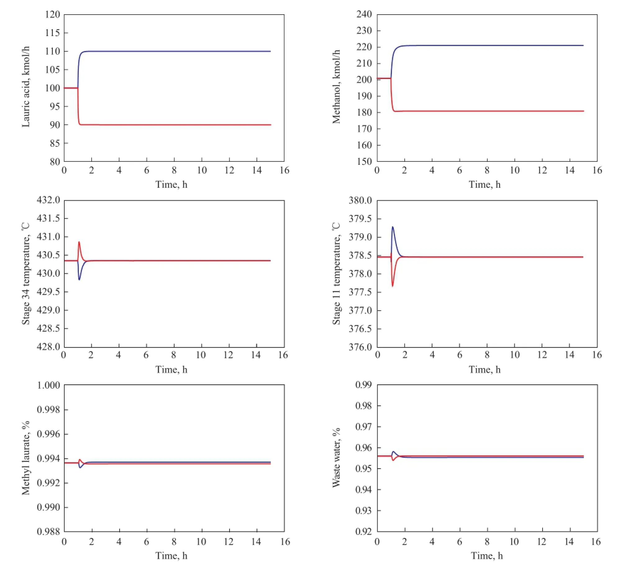
Figure 15 Dynamic response for ±10% fl owrate changes in laurate acid feed
6 Conclusions
In this paper, two thermally coupled designs for biodiesel production are studied to improve the energetic potentials. The sensitivity analysis is carried out to obtain the optimal designs for the proposed processes. The thermodynamic analysis and economic evaluation of the thermally coupled cases are evaluated. The calculation results show that the exergy loss in each column of the thermally coupled processes can be reduced. In addition, the TCSR-RD and TCSS-RD designs can provide signi fi cantly TAC savings reaching 11.97% and 23.41%, respectively. Moreover, the TCSS-RD design can obtain much more exergy loss and TAC savings than the TCSRRD design. Finally the dynamic characteristics of the TCSS-RD design are explored. The results show that the control scheme with two temperature loops can maintain the products at their desired purity. Hence the TCSSRD design is more suitable for the retrofit of biodiesel production process.
Acknowledgements: Financial supports of the National Natural Science Foundation of China (Grant: 21276279 and Grant: 21476261) and the Fundamental Research Funds for the Central Universities (No. 14CX05030A; No. 15CX06042A) are acknowledged with gratitude.
[1] Kiss A A, Omota F, Dimian A C, et al. The heterogeneous advantage: biodiesel by catalytic reactive distillation[J]. Topics in Catalysis, 2006, 40(1/4): 141-150
[2] Wu Jiang, Chen Boshui, Fang Jianhua, et al. Effect of biodiesel on oxidation stability, detergency and antiwear ability of diesel oil[J]. China Petroleum Processing & Petrochemical Technology, 2011, 13(4): 58-63
[3] Wang Yunpu, Fan Liangliang, Dai Leilei, et al. Synthesis of biodiesel using ZrO2polycrystalline ceramic foam catalyst in a tubular reactor[J]. China Petroleum Processing and Petrochemical Technology, 2015, 17(3): 67-75
[4] Kiss A A, Bildea C S. A review of biodiesel production by integrated reactive separation technologies[J]. Journal of Chemical Technology and Biotechnology, 2012, 87(7): 861-879
[5] Omota F, Dimian A C, Bliek A. Fatty acid esteri fi cation by reactive distillation. Part 1: equilibrium-based design[J]. Chemical Engineering Science, 2003, 58(14): 3159-3174
[6] Omota F, Dimian A C, Bliek A. Fatty acid esterification by reactive distillation: Part 2—kinetics-based design for sulphated zirconia catalysts[J]. Chemical Engineering Science, 2003, 58(14): 3175-3185
[7] Kiss A A, Dimian A C, Rothenberg G. Biodiesel by catalytic reactive distillation powered by metal oxides[J]. Energy & Fuels, 2007, 22(1): 598-604
[8] Dimian A C, Bildea C S, Omota F, et al. Innovative process for fatty acid esters by dual reactive distillation[J]. Computers & Chemical Engineering, 2009, 33(3): 743-750
[9] Nguyen N, Demirel Y. Using thermally coupled reactive distillation columns in biodiesel production[J]. Energy, 2011, 36(8): 4838-4847
[10] Kiss A A, Segovia-Hernández J G, Bildea C S, et al. Reactive DWC leading the way to FAME and fortune[J]. Fuel, 2012, 95: 352-359
[11] Ignat R M, Kiss A A. Optimal design, dynamics and control of a reactive DWC for biodiesel production[J]. Chemical Engineering Research and Design, 2013, 91(9): 1760-1767
[12] Kiss A A. Novel applications of dividing-wall column technology to biofuel production processes[J]. Journal of Chemical Technology and Biotechnology, 2013, 88(8): 1387-1404
[13] Kiss A A. Novel process for biodiesel by reactive absorption[J]. Separation and Purification Technology, 2009, 69(3): 280-287
[14] Nguyen N T. Optimization of biodiesel production plants[D].Lincoln: University of Nebraska-Lincoln, 2012
[15] Demirel Y. Thermodynamic analysis of separation systems[J]. Separation Science and Technology, 2004, 39(16): 3897-3942
[16] Nguyen N, Demirel Y. Retro fi t of distillation columns in biodiesel production plants[J]. Energy, 2010, 35(4): 1625-1632
[17] Douglas J M. Conceptual Design of Chemical Processes[M]. New York: McGraw-Hill, 1988
[18] Zhu Z, Wang L, Ma Y, et al. Separating an azeotropic mixture of toluene and ethanol via heat integration pressure swing distillation[J]. Computers & Chemical Engineering, 2015, 76: 137-149
[19] Huang K, Shan L, Zhu Q, et al. Adding rectifying/ stripping section type heat integration to a pressureswing distillation (PSD) process[J]. Applied Thermal Engineering, 2008, 28(8): 923-932
[20] Li Lumin, Liu Yuliang, Zhai Jian, et al. Design and control of self-heat recuperative distillation process for separation of close-boiling mixtures:n-Butanol and isobutanol[J]. China Petroleum Processing and Petrochemical Technology, 2015, 17(4): 111-120
[21] Luyben W L. Distillation Design and Control Using Aspen Simulation[M]. John Wiley & Sons, 2013
Received date: 2015-00-00; Accepted date: 2016-00-00.
Lanyi Sun. Tel.: +86-13854208340; Fax: +86-532-86981787;E-mail: sunlanyi@upc.edu.cn.
- 中国炼油与石油化工的其它文章
- Synthesis and Evaluation of Environmentally Friendly Calcium Isostearate Detergent with Excellent Oil Solubility
- Study on the Adaptability of Etheri fi cation Feedstock to Reactor Type
- Modeling of Isobutane/Butene Alkylation Using Solid Acid Catalysts in a Fixed Bed Reactor
- Analysis and Modeling of Wangqing Oil Shale Drying Characteristics in a Novel Fluidized Bed Dryer with Asynchronous Rotating Air Distributor
- Experimental and Molecular Simulations for Evaluating the Effect of Lubricity Improvers on the Property of Jet Fuel
- Preparation and Tribological Properties of Lanthanumdoped Muscovite Composite Particles as Lubricant Additives in Lithium Grease

