Stylized strokes for coherent line drawings
Liming Lou,Lu Wang(),and Xiangxu Meng
©The Author(s)2015.This article is published with open access at Springerlink.com
Stylized strokes for coherent line drawings
Liming Lou1,Lu Wang1(),and Xiangxu Meng1
©The Author(s)2015.This article is published with open access at Springerlink.com
Temporal coherence is one of the central challenges for rendering a stylized line.It is especially difficult for stylized contours of coarse meshes or nonuniformly sampled models,because those contours are polygonal feature edges on the models with no continuous correspondences between frames.We describe a novel and simple technique for constructing a 2D brush path along a 3D contour.We also introduce a 3D parameter propagation and re-parameterization procedure to construct stroke paths along the 2D brush path to draw coherently stylized feature lines with a wide range of styles.Our method runs in real-time for coarse or non-uniformly sampled models,making it suitable for interactive applications needing temporal coherence.
non-photorealistic rendering(NPR);line drawings;temporal coherence;stylized strokes
1 Introduction
Line drawings can effectively depict complex information for artistic illustrations,cartoons,and sketches,as they are simple,expressive,and rich in abstraction.In traditional line drawing,artists use ink,pencil,or charcoal to draw feature lines of objects,such as silhouettes depicting shape, suggestive contours as described by Ref.[1],and shadow boundaries.Line drawing algorithms often replicate this artistic workflow by firstly identifying the lines,and then rendering them with particular marks,such as textured brushes and graceful,curved strokes with attributes of colour,thickness,opacity, and so on.Both steps require special considerationto produce both spatially and temporally coherent animations.Spatial coherence requires the marks to be affixed to the 3D models during motion of the viewpoint.Temporal continuity minimizes abruptchangesin themarksfrom frameto frame.Perceptual studies[2,3]have shown that human observers are very sensitive to temporal artifactssuch aspopping and flickering.The visibility and attributes of the marks should vary smoothly to ensure temporal continuity.
Manyresearchershaveworked on extracting various lines from static 3D models represented by triangle meshes[4],such as occluding contours, ridges and valleys,suggestive contours,apparent ridges, and demarcating curves.Ofparticular interest are occluding contours(silhouettes),but coarse or non-uniformly sampled 3D models have meshes which are especially challenging for current methods.A dedicated method to handle them makes sense for specific applications(e.g.,video games, devices with limited computation power).However, the quality of stylized line drawings may suffer from two problems.Firstly,lines generated from meshes have tiny polygonal line fragments that collide in image space[5],and animation of such feature lines can cause popping and flickering effects which are easily observed.Secondly,there is a lack of temporal continuity as each feature line is generated independently and thus lacks information from neighboring frames.The challenge of rendering a mesh with coherent stylized contours is a subject of recent research.
Several researchers have addressed the problem of temporal continuity for stylized line drawing animations[5-9].They pay particular attention to tracing the lines in order to obtain coherent parameterization for stylization.However,most of these techniques need input models with sufficientdetail,and none of them consider meshes with undersampled or non-uniformly sampled faces.Feature lines extracted from such simplified meshes have sharp polygonal features and are more vulnerable to flickering and popping problems.They have no obvious or natural coherence in image space,unlike lines extracted from fine meshes with moderate complexity.
The main contribution of our method is to better handle stroke parameterization and temporal coherence especially for under-sampled geometry, by meansofstylized strokesalong 2D brush paths.Firstly,brush paths are constructed by linking pixels of projected visible contours in a certain order, allowing most line fragments to be avoided and long paths to be generated-this allows the method to work well for under-sampled or non-uniformly sampled meshes.Secondly,by using a 3D parameter propagation method from contours in the previous frame to ones in the current frame,parameters can be faithfully transferred to 2D brush paths,strokes can be generated faithfully along brush paths,sliding problems can be easily avoided,and stylized features can be kept when topology changes.
Four key steps are used to generate the stylized brush strokes in each frame: locating brush paths and generating stroke paths in image space (Section 4), propagating coherent parameters (Section 5.1),readjusting brush paths into stylized strokes according to the current parameters (Section 5.2),and recomputing coherent parameters for each stylized stroke(Section 5.3).Section 6 shows our results for coarse and non-uniform meshes and makes comparisons to other methods.Finally, Section 7 provides a summary and discusses further research directions.
2 Related work
Various research works have proposed coherent line drawing algorithms based on extracting lines and building correspondences between lines in multiple frames[10].
Line extraction.Line detection algorithms can be generally classified into image space methods and object space methods.
Imagespacealgorithms[11-14]usemodern graphics hardware to extract visible lines by image processing techniques.These visible lines lack 3D geometry information during animation and are represented by independent and unconnected pixels.
Objectspace algorithmsare based on 3D geometry,so it is easy to render the strokes in various width and painting styles.In order to obtain the accurate line visibility,hybrid approaches such as an ID reference buffer[15],an item buffer[16-18], or a depth buffer[19]are used to link adjacent pathsusing the connectivity ofthe extracted lines.However,simple heuristics based on distances and angles must be defined to solve ambiguities at line intersections,which lead to popping and overlaps in the stylized animation.Object space hidden lines removal algorithms,as in Refs.[20-22], avoid this problem at the price of high computational complexity but may produce many noisy,short segments lacking the spatial and temporal coherence needed for stylization.
In orderto dealwith theseproblems,our method uses a contour smoothing method [23] which interpolates over contour triangles to generate long,smooth,and coherent silhouette curves with 3D connectivity.Taking into account the screen projection of those curves,we construct brush paths to approximate the smooth shapes of 3D feature lines which generate and receive geometric information through the correspondence between curve points and brush particles.
Temporalcoherence. Thefirstcomplete method to render coherent stylized silhouettes by preserving stroke parameterization of individual lines between frames was Ref.[6].By transmitting part of the parameters via the image space samples in the previous frame and generating new parameters for the current frame,an energy function balances the coherence weights between 2D and 3D.This method is mainly appropriate for high complexity models; its results are not smooth for under-sampled models, and lead to line fragments for high complexity models.
The approach of Ref.[7]is very appropriate when zooming in or out by a significant factor,and for parallel nearby lines.It works by precomputing self-similarity and smoothly varying linemaps to paramet erize adjacent feature lines.However, popping artifacts may happen when multiple lines merge into a single line.The method in Ref.[8] needs to know the viewpoint sequence in advance, and reconstructs a parameterized space-time surfaceby sweeping lines during the animation.This allows the determination of changes in line topology,but at the expense of high computational cost.The method of Ref.[9]introduces an energy minimizing active contour method to trace on the 3D object across frames and to detect topological events,but it still can produce line fragments.The method in Ref.[5]combines 2D active strokes and brush paths to approximate the model shape and deal with topological change events.Because the active contours are generated by image space algorithms, this method merges adjacent paths using many complex heuristics.Inspired by Ref.[5],in our method stylized strokes not only take advantage of geometric information to avoid problems due to topological changes,but also offer control over the trade off between temporal coherence and spatial coherence during stylization.
3 Overview
In order to draw coherent stylized brush strokes from meshes,two questions must be addressed: firstly,how to generatesmooth brush strokes from polygonal mesh surfaces;secondly,how to propagate parameters from one frame to the next to maintain the coherence,especially when topology changes.Figure 1 shows the key steps of our method applied to two consecutive frames.
Firstly,the 3D feature lines extracted from the objects must be smoothed to reduce tessellation artifacts. Based on the reference ID image and the 3D contour curve lists,we can locate the corresponding projected pixels for each curve point and then link them into long connected brush paths in a reasonable order using a novel linking procedure described in Section 4.
Secondly,to avoid sliding and flickering effects caused by 2D parameterpropagation,and to eliminatepopping and discontinuous stylization effects produced by 3D parameter propagation after screen projection,we propagate parameters in three steps as described in Section 5.1.Section 5.2 proposes a resizing analysis algorithm to split long brush strokes into small strokes which are the stylized units.Some parameters are missing since Section 5.1 does not give a one-to-one relationship and some parameters may not be monotonic with respect to arc-length of their stylized strokes.In Section 5.3,we use a least-squares method to fit parameters for each stylized brush path to balance the goals of coherence on the 3D shape and 2D arc-length parameterization.
4 Brush path generation
4.1 Smooth contour extraction
Our method requires triangle meshes as input.In Ref.[23],a method was proposed to smooth the silhouettes of coarse triangle meshes.We use their method to reconstruct curves in 3D and introduce a simple local remeshing procedure to compute 3D silhouette chains for non-uniform meshes based on contour triangles.
Occluding contour(or silhouette)curves of a mesh can be computed using the property that the surface normal of any point on the silhouette is perpendicular to the viewing direction.Firstly, contour triangles are identified by checking the visibility of all mesh vertices.If the three vertices of a triangle do not have the same visibility for a given viewing direction D,the triangle face is considered to be a contour triangle which contains contour curves.As shown in Fig.2,△v1v2v3is a contour triangle,because v1has different visibility to v2and v3.Let N1,N2,and N3be estimated normal vectors at these vertices which are known.We can compute the normal vectors˜N for points S(u0)and S(v0)by Eqs.(1)and(2).Contour points S(u0)and S(v0)can be found by solving Eq.(3),where t1andt2are the tangent vectors of v1and v2.

Fig.1 Overview of process:(a)coarse mesh of knot,(b)brush paths in frame fi,(c)stroke paths in fi,(d)strokes in fi,(e)brush paths in frame fi+1,(f)3D propagation,(g)stroke paths in fi+1,and(h)strokes in fi+1.
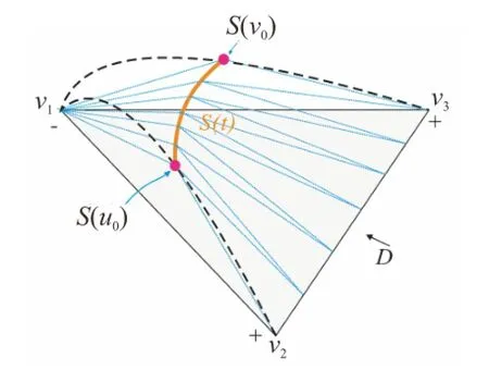
Fig.2 Construction of a smooth contour curve.The orange line S(t)is the silhouette edge,while blue lines bound new triangles after local remeshing.

After the two silhouette points S(u0)and S(v0) have been found together with their normal vectors ˜N(u0)and ˜N(v0),smooth silhouette curves S(t) can be computed using Hermite interpolation as in Eq.(3)[23].
The silhouette curve S(t)is next adaptively sampled into silhouette segments based on its screen projected arc-length to ensure the silhouette curves are smooth after sampling.We fix the maximum projected length of each silhouette segment to 2 pixels.Finally,local remeshing is done for each contour triangle by adding triangles passing through the sample points located on the silhouette curves (see Fig.2).
Taking advantage oftemporalcoherence of contours,we randomly choose a contour triangle found in the previous frame as a starting triangle to start a new search in the current frame.When a new contour triangle is found,its neighboring triangles including further contour triangles can be readily found,leveraging spatial coherence.Each contour triangle is connected to only two other contour triangles on the mesh in most cases[20].Figure 3 compares results of smoothing contours by the method in Ref.[21].
4.2 2D brush path construction

Fig.3 Contour smoothing:(a)coarse mesh of torus(144 triangles),(b)silhouette edges determined by Ref.[21],and(c) smooth contour curves produced by our method.
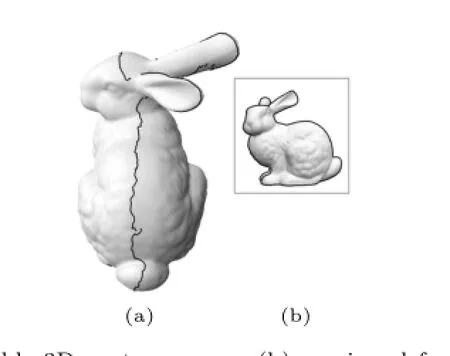
Fig.4 Visible 3D contour curves(b)as viewed from another angle(a).
As discussed in Section 5.1,the stylized parameters are firstly assigned at equal spacing along the stroke path in 2D space.During parameter propagation,we transfer the parameters to the corresponding curve point in 3D.We then transfer the parameters from the 3D curve points in the previous frame to their nearest 3D curve points in the next frame.Finally, we transfer the parameters from the 3D curve to their projected pixels in the current frame in 2D space.The goal of this complex procedure is to produce single-pixel width paths in 2D space which is called brush paths.Every pixel on the brush path must be matched to a curve point in 3D to support parameter propagation.Another advantage of this kind of brush path is that it can readily guide correct parameter propagation at the intersection of two brush paths.
After we draw 3D contour lines to construct an ID reference image,as described by Ref.[16],we next determine the corresponding relationship which is one-to-many or one-to-one between the visible 3D curve points and pixels in the ID reference image as shown in Fig.5.Every 3D curve point has an order parameter O which represents the order in which it is drawn on the 3D contour curve;and then it is projected to one or more pixels in screen space with coordinates(x,y)and transfer the parameter O from 3D points to 2D pixels.We denote O(x,y)as the order parameter for each pixel.Another important parameter is the weight W(x,y)for each pixel,which can be computed by the order parameter of its 3×3 neighbourhood using Eq.(4).

In practice,we specify δ as 5.The weight parameter is helpful to determine that even if two pixels are quite near in 2D but actually separated in 3D,they should not be merged into a brush path according to the following linking procedure.An optimal choice of δ can eliminate ambiguity at the intersections of paths and guide the linking procedure to find the next pixel during brush path construction.
We now discuss how to link pixels into brush paths.The linking procedure iterates through all pixels in the ascending order of parameter O.Once a pixel is added to a brush path,it is set as visited.The linking procedure has two parts:firstly finding the starting pixel for each brush path,and secondly searching from the starting pixel to construct the brush path.
1)Finding the start pixel for each brush.Find pixelswith smallestO amongstallun-visited pixels.The one with the smallest weight is set as the starting point.Add this pixel to the brush path.For example,pixel with O(x,y)=20 and W(x,y)=2 in Fig.5 is the starting pixel of the red path.
2) Constructing a brush path. Set the starting pixel as current pixel and find linking candidates.Firstly,find all unvisited neighbouring pixels(xi,yj)of current pixel(xc,yc)in its 3×3 neighbourhood which satisfies Inequality(5).For example,when the current pixel is the pixel with O(x,y)=27 and W(x,y)=2 in Fig.5,there are four unvisited pixels in its neighbourhood;however, only one candidate pixel with O(x,y)=28 and W(x,y)=1 satisfies Inequality(5).So it is added to the brush path and visited,and will be the next current pixel.
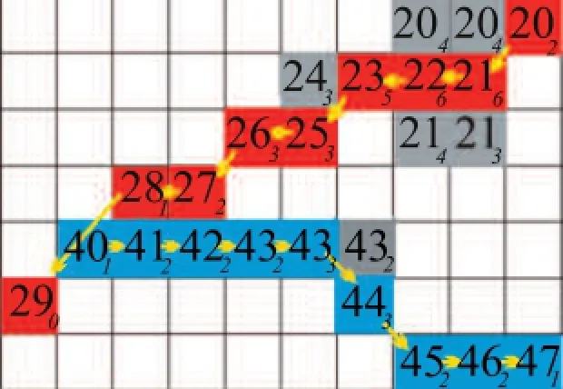
Fig.5 Close up of a reference image.The number on each pixel is the order parameter O transferred from its corresponding 3D point.The number as the right subscript of each pixel presents its weight W(x,y)parameter.Our algorithm generates two brush paths as shown in red and blue.The sequence for the red path is 20,21,22,23,25,26,27,28,29.The sequence for the blue path is 40,41,42,43,43,44,45,46,47.

The next current pixel is the one with maximum weight amongst all candidates.If there is more than one,select the one with maximum O.If no candidate is found for the current pixel,the search process should enlarge the neighbourhood to 5×5,which ensures we can find the correct direction even at intersections.
5 Coherent stylization
Defining the parameter C as texture coordinates of each stroke,stylization is mapped onto the stroke path via C.To achieve temporal coherence,we first collect pairs of corresponding pixels from the previous frame and the current frame via the contour triangles,using three steps,and then propagate parameter C between them-see Section 5.1.We then traverse the brush path to generate stroke paths according to the parameter information-see Section 5.2.
5.1 Parameter propagation
Every pixel on the brush path has four parameters: the corresponding contour triangle V on the mesh, the corresponding 3D curve point P,the stroke path ID Isin the previous frame,and the parameter C.If 2D samples are propagated directly then“screen door”or texture sliding problems arise because the passed parameters may become disordered and correspond to the wrong brushes in the propagation process.To address this problem,we propose a three-step parameter propagation method based on contour triangles.
In the first step,the parameter is propagated from each brush pixel to the corresponding 3D curve point in the previous frame.In the second step,for each 3D contour curve point in the previous frame,we readily find the nearest curve point on the contour curves in the current frame using the flooding algorithm described below.Thus,the parameter can be propagated from each 3D contour curve point in the previous frame to the nearest contour curve point in the current frame.In the third step,the parameteris transformed to the corresponding brush pixel from the current curve in the current frame,as shown in Fig.6.
Taking a sample point p on a brush path of frame fias an example,with parameters(C,Is,P,V),V is represented as Δv1v2v3in Fig.7.In the flooding algorithm,we search adjacent triangles of Δv1v2v3in frame fi+1ring by ring(all triangles which share at least one point with Δv1v2v3are the first ring and so on).If contour triangles exist,we check all contour points on these triangles and compute the nearest one P'to P in 3D space.The 3D Euclidean distance is used to find the closest contour point.It is a reasonable approximation when the contours do not move too far on the surface between two successive frames.For larger motions,picking the closest point in 3D does not guarantee to find the most appropriate correspondence(since contours travel at different“speeds”on the surface),and is likely to increase the distortion of the parameterization.If none is found,we flood the current ring to find more neighbouring triangles of Δv1v2v3and further tests are done to find the nearest contour point.We do flooding twice at most in practice.As contour triangles are spatially coherent between frames,most searches succeed immediately in the first ring.If we find a corresponding point P'to the point P,and the projected pixels p'of P'appear in the brush path of frame fi+1,we transfer the parameter information from sample point P,including C and Is,to P'on the contour path of frame fi+1.
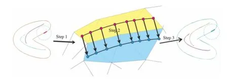
Fig.6 Parameter propagation between frames fiand fi+1.
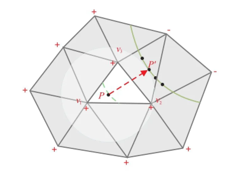
Fig.7 3D space propagation based on contour triangles.
5.2 Stroke construction
We generate one or more stroke paths along each brush path based on the parameter information received from the previous frame.We use the rule that pixels on the same 2D brush path with the same stroke path ID from the previous frame should be grouped as a stroke path,and parameterized as one stroke,in a similar way to the key idea of Ref.[6].
As mentioned in Section 5.1,brush paths may split,merge,become shorter or longer,or even disappear or newly appear during animation.Thus some pixels on brush paths will fail to propagate parameters.Wedefinevariousrulesto divide the brush paths into stroke paths by taking the parameters into account.We collect the pixels whose parameters are in the same group in the previous frame as a stroke group.Each pixel in stroke group G is parameterized as(li,ci),where liis the arc-length from the first pixel in group G.Even in the same stroke group the parameter c may be out of order: parameter monotonicity means that c should either increase or decrease along the 2D brush path.Also, two nearby groups may have gaps,overlaps,or inclusion.
To address such problems we deal with the stroke groups for each brush path as follows.
1)Pixels on a brush path with the same stroke path ID from the previous frame are first classified into the same stroke group G.Then,we must make sure that parameter t on each stroke group preserves the same monotonic order as the previous frame.We discard any group whose number of pixels is less than a threshold.
2)If two nearby groups overlap,the parameters of the overlapping pixels should be removed,to eliminate the overlapping portions as shown in Fig.8(a).
3)We use a difference solution to the trimmed one-to-one policy used in Ref.[6]to deal with any gap between neighbouring stroke groups.We first assume all sequential pixels in the gap belong to one group and compute their new parameters using the fitting method in Section 5.3.If any of the newly computed parameters lie outside the range[0,1],then we mix them together with the other group in thefitting method(see Fig.8(c)).Each group has a monotonicity rate in c which is defined as the length of the monotonic range divided by the number of pixels on the stroke path,and extended stroke paths should obey this rate.If some pixels’parameters still lie outside this range,we regard them as the seeds of new strokes,as shown in Fig.8(b).
4)We again differ from Ref.[6]in how to deal with a stroke group belonging to multiple brush paths, which means a topology change has happened.We gather these pixels as a special group from all brush paths,as input to the fitting method,so as to keep the stylization coherent.After computing the parameters for this special group,we regard them as a stroke path.
Becauseboth brush path and strokegroup information are considered,coherence is kept when topology changes as shown in Fig.9.
5.3 Stroke parameterization
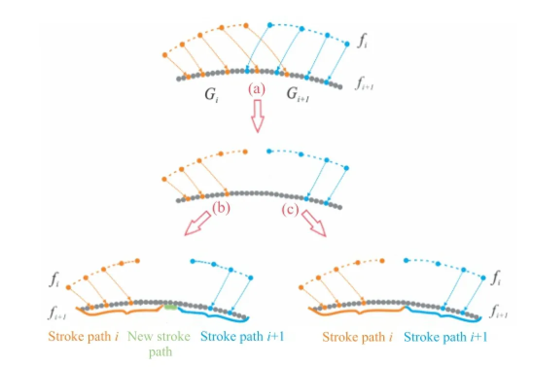
Fig.8 Stroke path construction.
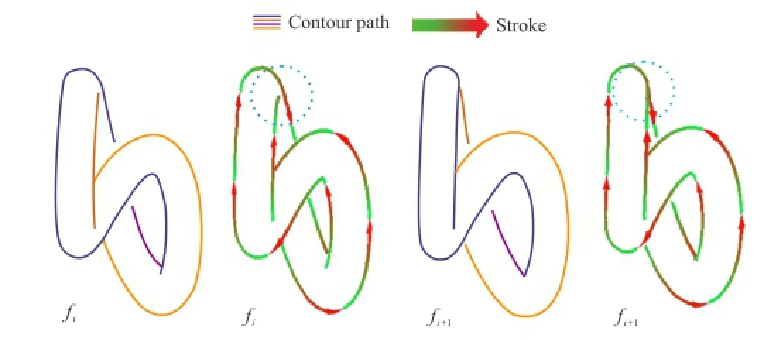
Fig.9 Coherent strokes when topology changes.
The parameter c within a same stroke group is monotonic.We now describe the scheme for parameterizing a stroke path for sample pixels described by(l,c),where l is the arc-length from the pixel to the start point of the stroke path.In order to balance the competing goals of coherence on the3D shapeand uniform 2D arc-length parameterization,we use least-squares fitting to recompute the parameter of each stroke path.This globally ensures monotonicity of the stroke path and locally minimizes deviation from the faithful voting points which are the pixels in each stroke group.The parameters are generated in a coherent way.Given vote samples(li,ci)(i=0,···,m)on a stroke group, we use the least-squares function Clc(l)to fit the votes to minimizewhere

and

Figure 10 illustrates our linear fitting method in comparison to other approaches.The phase fitting method uses uniform 2D arc-length parameterization,which is good for panning or zooming,but produces sliding along the contours (Fig.10(a)).The interpolation method promotes coherence on the 3D shape by simply interpolating the samples,but this effect is not desirable for styles such as dots that need consistent spacing between elements(Fig.10(b)).The optimized method in Ref.[6]balances 3D shape and uniform 2D arclength parameterization,but lacks smoothness,so the generated strokes may be not spatially smooth or stable over time(Fig.10(c)).Our method usesleast-squares fit parameters,which generates C1coherent fitting curves,producing strokes which change continuously(Fig.10(d)).
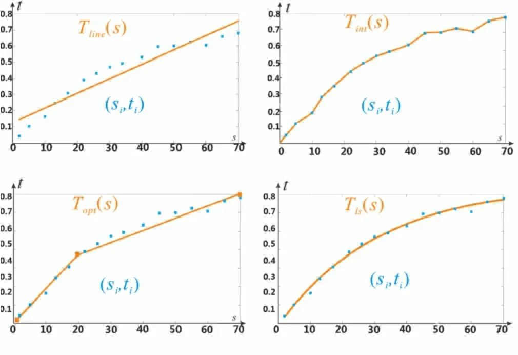
Fig.10 Four schemes for assigning the parameterization C(l) (red lines)to a stroke path given vote samples(li,ci)(blue points).
6 Results
In this section,we present results of testing our method for a variety of 3D models with stylized contours.We compare our method with the methods of Refs.[5]and[6]in terms of rendering quality and efficiency.We test all methods on a PC with a 3.4 GHz CPU,8 GB of memory,and a Nvidia GeForce GTX 550 Ti graphics card.The implementation runs on a single CPU without exploiting multi-threading.The window size is set to 512×512.The rendered objects cover about 40%-60%of the window.
Figures 9 and 11-14 show examples generated by our method.The resulting stylized contours are smooth and temporally coherent across a wide range of styles and camera motions,even when topology changes occur.Because contour smoothing is used, our method is suitable for coarse meshes such as the dino and the camel illustrated in Figs.13 and 14.

Fig.11 Stylized results for the fish(5000 triangles).

Fig.12 Stylized results for the horse(6046 triangles).
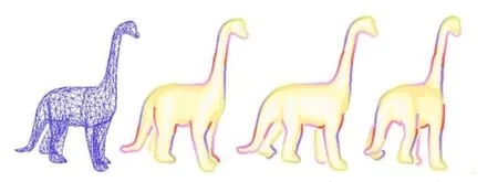
Fig.13 Stylized results for the dino(2000 triangles).
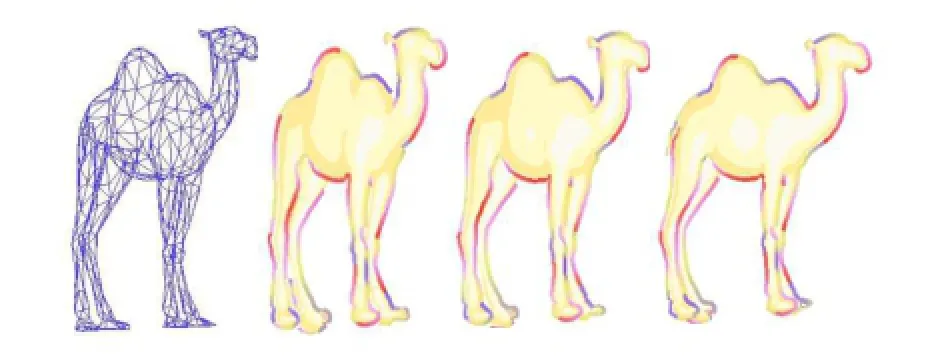
Fig.14 Stylized results for the camel(1000 triangles).
Figurer 15 compares stylized results with naive arc-length textures for our method and the method ofRef.[6].Ourmethod can prevent sliding of the sharp spine above the head from leftto right.However,sincethefitted cubic parameterization deviates from uniform 2D arclength,it also leads to some stretching artifacts.The same problem happens to the method of Ref.[6]if we adjust the optimization weights to avoid sliding of the spikes.
Figure 16 compares our method with the method in Ref.[6]when a fine mesh is used.Many short strokes appear in the result of Ref.[6], as short 3D contour paths are not connected for stylization.Our method can efficiently solve the problem by generating 2D contour paths.However, a limitation of our linking procedure is that the interval range and the gap threshold value in Section 4 are global.On one hand,this prevents merging contours that are far apart in 3D but well aligned in 2D,but on the other hand,it does not work well for complex bumpy shapes,such as the area near the bunny’s ear where artifacts can be seen in the supplemental video.
Figure 17 compares our method with the method in Ref.[6]using a coarse mesh.The latter method leads to broken lines,as the silhouette segments used which are corresponded to mesh triangles and always pass through mesh faces,can disappear or appearsuddenly,leading to visual artifacts.In contrast,our method generates a more faithful smooth contour that is visually coherent with a moving viewpoint or a moving object.
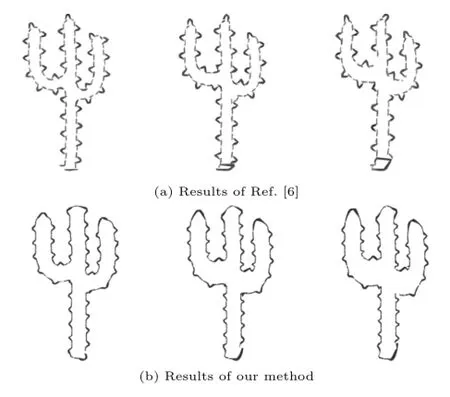
Fig.15 Stylized results for the cactus.

Fig.16 Results for the Stanford bunny(10000 triangles):(a)fine mesh,(b)-(d)results of our method,and(e)-(g)results of the method in Ref.[6].

Fig.17 Results for the knot(480 triangles):(a)coarse mesh,(b)-(d)results of our method,and(e)-(g)results of the method in Ref.[6].
Figure 18 compares stylized results for our method and the method in Ref.[5].Note a,b,and c, three strokes near the T junction in frame fi−1.As the model rotates,the 3D position of point c is gradually covered by b and position b becomes closer and closer to position a.Thus,stylization of stroke c ceases to contribute,and it is better to merge strokes a and b in the same brush path to depict the model shape.It is easy to see that,although B´enard’s method keeps the stroke segment consistent as far as possible,sometimes this strategy incorrectly connects contours,especially when occlusion relations change.This is due to only considering local 2D proximity and alignment in 2D space for feature line vectorization.In our method, brush paths are connected by combining 3D and 2D information,which can efficiently avoid these problems while retaining real-time performance.
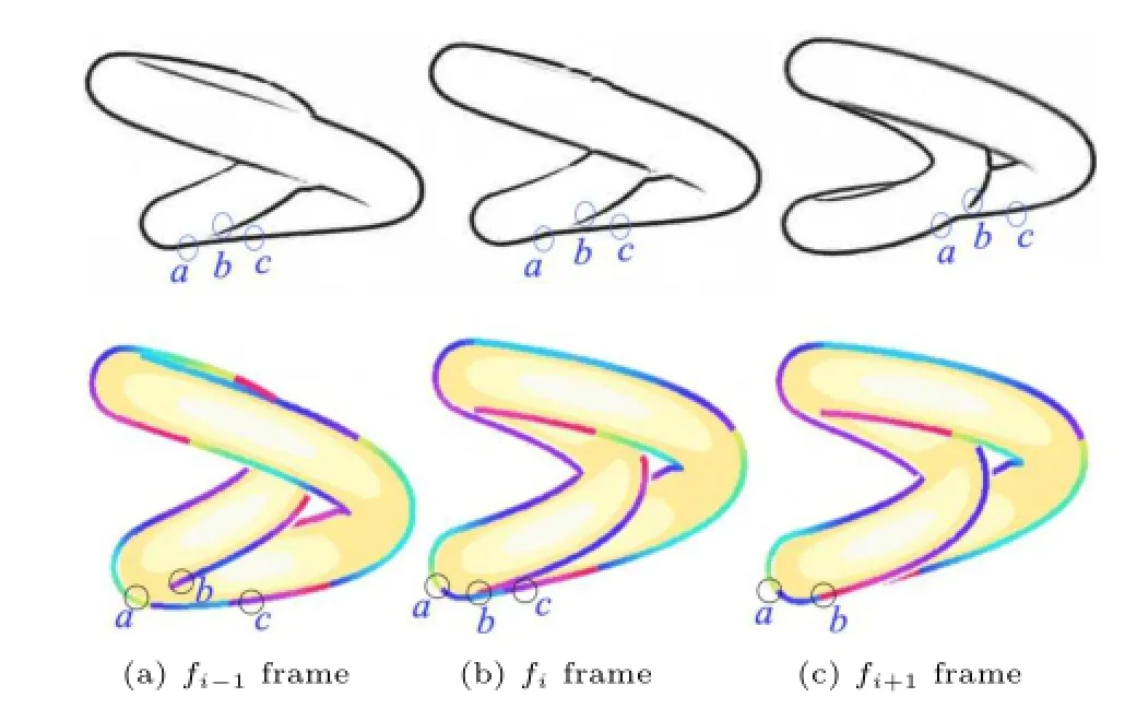
Fig.18 Results for the knot(15000 triangles).Top:results from the method in Ref.[5].Bottom:results from our method.
Table 1 compares the frame rates when applying our method and the method in Ref.[6].After we fix the lengths of strokes rendered for each model in the first frame,the read-back of the ID image and constructing the 2D brush path by pixels are the performance bottlenecks that reduce the frame rate.Because our method generates 2D brush paths, our method needs to read the ID image once,and 100 frames are used due to 2D brush path connections, so the frame rate of our method is lower than that achieved in Ref.[6].This could be improved by using GPUs in future.Also,the results of Ref.[6]exhibit long gaps or broken lines which our method improves on.It is easy to see from Table 1 that for models with similar numbers of faces,more stroke paths lead to slower performance.As the same stroke length is used throughout in Table 1,the number of stroke paths is correlated with the complexity of the lines and the number of pixels in the windows.
7 Conclusions
We present a way to render coherent stylized contours of3D meshes and demonstrate its effectiveness for a variety of models.Our method generatessmooth and coherentcontoursby a contour interpolation method based on 3D contour triangles.We use a 3D point propagation method based on contour triangles to propagate parametersfrom one frame to the next.The propagation is more accurate for coarse meshes and avoids sliding problems.New stroke paths are constructed by considering 2D brush paths and stroke groups.Our method can balance coherence between the 3D shape and uniform 2D arc-length parameterization by a least-squares fitting method to refit parameters on each stroke path.Our method can generate coherent stylized line drawings with temporal coherence for meshes,including coarse meshes and non-uniformly sampled meshes,automatically at interactive rates.

Table 1 Performance comparisons of our method and Kalnin’s method.
Acknowledgements
We would like to thank the anonymous reviewers for helpful suggestions.This work was supported by the National Natural Science Foundation of China(Nos. 61472224 and 61472225),the National High-tech R&D Program of China(No.2012AA01A306), the special fund for Independent Innovation and Transformation ofAchievements in Shandong Province(No.2014zzcx08201),the special funds of the Taishan Scholar Construction Project,and the China Scholarship Council(No.201406220065).
Open Access This article is distributed under the terms of the Creative Commons Attribution License which permits any use,distribution,and reproduction in any medium,provided the original author(s)and the source are credited.
[1]DeCarlo,D.; Finkelstein,A.; Rusinkiewicz,S.; Santella, A.Suggestive contours for conveying shape.ACM Transactions on Graphics Vol.22,No.3, 848-855,2003.
[2]Yantis, S.; Jonides, J.Abrupt visualonsets and selective attention: Evidence from visual search.Journal of Experimental Psychology:Human Perception and Performance Vol.10,No.5,601-621, 1984.
[3]Schwarz,M.;Stamminger,M.On predicting visual popping in dynamic scenes.In:Proceedings of the 6th Symposium on Applied Perception in Graphics and Visualization,93-100,2009.
[4]DeCarlo,D.Depicting 3D shape using lines.In: Proc.SPIE 8291,Human Vision and Electronic Imaging XVII,829116,2012.
[5]B´enard,P.; Lu,J.;Cole,F.; Finkelstein,A.; Thollot,J.Active strokes:Coherent line stylization for animated 3D models.In:Proceedings of the Symposium on Non-Photorealistic Animation and Rendering,37-46,2012.
[6]Kalnins,R.D.;Davidson,P.L.;Markosian,L.; Finkelstein,A.Coherent stylized silhouettes.ACM Transactions on Graphics Vol.22,No.3,856-861, 2003.
[7]B´enard,P.;Cole,F.;Golovinskiy,A.;Finkelstein, A. Self-similar texture for coherent line stylization.In:Proceedings of the 8th International Symposium on Non-Photorealistic Animation and Rendering,91-97,2010.
[8]Buchholz,B.; Faraj,N.;Paris,S.; Eisemann, E.; Boubekeur, T.Spatio-temporalanalysisfor parameterizing animated lines.In:Proceedings of the ACM SIGGRAPH/Eurographics Symposium on Non-Photorealistic Animation and Rendering,85-92,2011.
[9]Karsch, K.; Hart, J. C. Snaxels on a plane.In:Proceedings of the ACM SIGGRAPH/ Eurographics Symposium on Non-Photorealistic Animation and Rendering,35-42,2011.
[10]B´enard,P.;Bousseau,A.;Thollot,J.State-ofthe-art report on temporal coherence for stylized animations.Computer Graphics Forum Vol.30,No.8, 2367-2386,2011.
[11]McGuire,M.;Ekanayake,C.;St-Amour,J.-F.;Hal´en, H.;Thibault,A.;Martel,B.Stylized rendering in games.In:SIGGRAPH 2010 Course.Available at http://graphics.cs.williams.edu/courses/SRG10/.
[12]Saito,T.;Takahashi,T.Comprehensible rendering of 3-D shapes.ACM SIGGRAPH Computer Graphics Vol.24,No.4,197-206,1990.
[13]Nienhaus,M.;D¨ollner,J.Blueprint rendering and“sketchy drawings”.In: GPU Gems2.Pharr, M.Ed.Addison-Wesley,235-252,2005.
[14]Vergne,R.;Vanderhaeghe,D.;Chen,J.;Barla, P.;Granier,X.;Schlick,C.Implicit brushes for stylized line-based rendering.ComputerGraphics Forum Vol.30,No.2,513-522,2011.
[15]Bourdev, L.Rendering nonphotorealistic strokes with temporal and arc-length coherence.Technical report.Brown University,1998.Available at http:// pages.cpsc.ucalgary.ca/~mario/npr-theses/Bourdev-MSc-98.pdf.
[16]Northrup,J.D.;Markosian,L.Artistic silhouettes: A hybrid approach.In:Proceedingsofthe1st international symposium on Non-photorealistic animation and rendering,31-37,2000.
[17]Kalnins,R.D.;Markosian,L.;Meier,B.J.;Kowalski, M.A.;Lee,J.C.;Davidson,P.L.;Webb,M.;Hughes, J.F.;Finkelstein,A.WYSIWYG NPR:Drawing strokes directly on 3D models.ACM Transactions on Graphics Vol.21,No.3,755-762,2002.
[18]Cole,F.;DeCarlo,D.;Finkelstein,A.;Kin,K.; Morley,K.;Santella,A.Directing gaze in 3D models with stylized focus.In:Proceedings of the 17th Eurographics conference on Rendering Techniques, 377-387,2006.
[19]Isenberg,T.;Halper,N.;Strothotte,T.Stylizing silhouettesatinteractiverates: From silhouette edges to silhouette strokes.Computer Graphics Forum Vol.21,No.3,249-258,2002.
[20]Markosian,L.;Kowalski,M.A.;Goldstein,D.; Trychin,S.J.;Hughes,J.F.;Bourdev,L.D.Realtime nonphotorealistic rendering.In:Proceedings of the 24th annual conference on Computer graphics and interactive techniques,415-420,1997.
[21]Hertzmann, A.; Zorin, D.Illustrating smooth surfaces.In:Proceedings of the 27th annual conference on Computer graphics and interactive techniques,517-526,2000.
[22]Grabli, S.; Turquin, E.; Durand, F.; Sillion, F.X.Programmable rendering of line drawing from 3D scenes.ACM Transactions on Graphics Vol.29, No.2,Article No.18,2010.
[23]Wang,L.;Tu,C.;Wang,W.;Meng,X.;Chan,B.; Yan,D.Silhouette smoothing for real-time rendering of mesh surfaces.IEEE Transactions on Visualization and Computer Graphic Vol.14,No.3,640-652,2008.
Liming Lou received her B.S.degree from theDepartmentofComputer Science, Shandong University in 2007. She is a Ph.D. candidate in the Department of Computer Science and Technology, Shandong University,Jinan,China,and currently a visiting student in the University of Virginia.Her research interests include non-photorealistic rendering and image and video processing.
Lu Wang received the Ph.D.degree from theDepartmentofComputer Science, Shandong University, in 2009.She is an associate professor in the School of Computer Science and Technology,Shandong University.Her research interests include computer graphics, photorealistic rendering, non-photorealistic rendering,and geometric modeling.
Xiangxu Meng received the B.S.and M.Eng.degrees from the Department of Computer Science, Shandong University,Jinan,China in 1982 and 1985,respectively,and the Ph.D.degree from the Institute of Computing Technology, Chinese Academy of Sciences,in 1998.He is a professor in the School of Computer Science and Technology,Shandong University.His current research interests include humancomputer interaction,virtual reality,computer graphics, CAD/CAM/CIMS,visualization,and scientific computing.
1School of Computer Science and Technology,Shandong University,Jinan,China.E-mail:luwang hcivr@sdu. edu.cn().
Manuscript received:2014-11-07;accepted:2015-02-26
 Computational Visual Media2015年1期
- Computational Visual Media的其它文章
- Region-based structure line detection for cartoons
- Salt and pepper noise removal in surveillance video based on low-rank matrix recovery
- Panorama completion for street views
- Edge-preserving image decomposition via joint weighted least squares
- Least-squares images for edge-preserving smoothing
- Poisson disk sampling through disk packing
