Drag of a D-shaped bluff body under small amplitude harmonic actuation
Yqing Li,Honglei Bi,Nn Go,∗
aSchool of Aeronautics and Astronautics,Dalian University of Technology,Dalian 116024,China
bDepartment of Mechanical Engineering,University of Melbourne,Melbourne,Australia
cState Key Laboratory of Aerodynamics,Mianyang 621000,Sichuan,China
Drag of a D-shaped bluff body under small amplitude harmonic actuation
Yaqing Lia,Honglei Baib,c,Nan Gaoa,∗
aSchool of Aeronautics and Astronautics,Dalian University of Technology,Dalian 116024,China
bDepartment of Mechanical Engineering,University of Melbourne,Melbourne,Australia
cState Key Laboratory of Aerodynamics,Mianyang 621000,Sichuan,China
A R T I C L E I N F O
Article history:
Received 10 November 2014
Accepted 29 December 2014
Available online 16 February 2015
D-shaped bluff body
Open-loop flow control method was used to affect the development of a turbulent wake behind a D-shaped bluff body.Loud speakers were embedded inside the bluff body to produce two zero-net-massflux jets through 2 mm-wide span-wise slots located along the upper and lower edges on the rear wall. The drag forces for different actuation amplitudes(Cµ,the ratio between the momentum of the actuating jets and the moment deficit caused by the bluff body)and frequencies(StA)were examined.The effects of the phase difference in the two jets(0 andπ)were also studied.It was found that when Cµwas 0.1%,a drag reduction up to 5%was achieved when the velocities of the two jets varied in phase at a frequency of StA=0.16.When the velocities of the two jets variedπout of phase,significant drag increase was observed.
©2015 The Authors.Published by Elsevier Ltd on behalf of The Chinese Society of Theoretical and Applied Mechanics.This is an open access article under the CC BY-NC-ND license(http:// creativecommons.org/licenses/by-nc-nd/4.0/).
Flow separation over a bluff body can be found in many applications.Effectively controlling the development of the wake structures can reduce the form drag associated with the flow separations.Zero-net-mass-flux jet(or synthetic jet)actuator was widely used in the active control of separated flows.Compared with the passive control methods such as vortex generators,the active control methods have higher efficiency and better robustness.The periodic perturbations of the flow near the separation region promote the development of the large scale structures and enhance the momentumtransportacross the shearlayer.The pressure on the solid surface,the trajectory of the shear layer and the size of the re-circulation region are thus changed[1-5].Multiple synthetic jet actuators was also used to control the separated flow.Bigger et al.[6]used an array of 6 zero-net-mass-flux jets distributed azimuthally around the edge of a disk to control the wake.They found the size of the separation region could be reduced as much as 10%when the actions of the actuators were in phase and the momentum ratio Cµwas 0.4%.As much as 15%reduction in the separation length was found when the helical actuation was used where the phase difference between the adjacent actuators wasπ/3.Vukasinovic et al.[7]used an array of 11 actuators located azimuthally on a halfcircle around a hemisphere.They found that the separation length was reduced significantly when the actuation frequency was about10 times ofthe naturalshedding frequency(StA=17.4-30.5),and the momentum ratio of the jets was 0.75%-2.3%.Recently,Pastoor et al.[8]used a pair of synthetic jet actuators to force the wake behind a D-shaped body located in the center of a wind tunnel.The actuator issued oscillating jet flow from the upper and the lower edges of the rear surface and the velocity variations ofthe two actuators were in phase.They found the drag was reduced when the actuation frequency was smaller than the natural shedding frequency(0.1<StA<0.2)but increased when the actuation frequency was close to the natural shedding frequency of the turbulent wake(StA=Sto=0.24).When the actuation frequency was StA=0.15 and Cµwas larger than 0.5%,the drag was reduced by approximately 15%for the flow with a Reynolds number of 47000.
Pastoor et al.[8]did notexamined closely how the drag changed with the actuation frequency and amplitude for smaller actuation amplitudes,particularly for momentum ratio(Cµ)less than 0.2%. The open loop control was conducted in the present investigation using a similar D-shaped body with momentum ratio less than 0.2% where Pastoor et al.[8]only studied a few combinations of actuation amplitude and actuation frequency.Smoke-wire visualization technique was also used to study the effect of actuation on the development of the large scale flow structures.The experimental methodologies will be presented in the next section,followed by the results and the summaries.
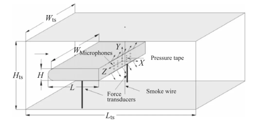
Fig.1.Schematics of the test section in the wind tunnel.
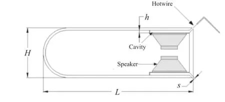
Fig.2.Schematics of the D-shaped body.

The D-shaped body was supported by two aluminum square bars located at 123.5 mm downstream of the leading edge(or x=-165 mm)and z=±135 mm.The bars also served as force transducers with strain gauges glued to the center of the bars.The bars were drilled with equally spaced 2.4 mm holes at the locations above and below the strain gauges to minimize the drag caused by the supporting bars.Signals from the strain gauges were amplified using an amplifier with a gain of 100.
There are two columns(z/H=±0.44)and 4 rows(y/H= ±0.08,±0.24)of 1 mm diameter pressure taps were mounted on the rear wall of the bluff body.Each pressure tap was connected to a CYH-130 pressure transducer using a 0.8 mm inner diameter flexible tubing to measure the mean static pressure on the rear wall.The pressure transducer was calibrated using a YJB-2500 water manometer with a resolution of 0.1 Pa.

Smoke-wire visualization technique was used to study the evolution of the flow structures.A 304 stainless steel wire with a diameter of 0.1 mm was stretched vertically at 5 mm downstream ofthe rear surface of the bluffbody along in the centralplane ofthe tunnel(x/H=0.08,z=0).The metal wire was connected to two 2200µF capacitors using aluminum electrodes and heavy gauge wires.The capacitors discharged high current electricity through the metal wire and vaporized liquid droplets attached to the wire producing smoke filaments.A short amount of time after the start of discharging,a triggering signal was sent to the camera and the flash to record the streak-lines.The actions were controlled by a timing circuit with an Atmega16 micro-controller.The discharge voltage of the capacitor was set to 75 V(corresponding to a peak current of approximately 10 A)and the time delay between the discharging and the shutter triggering signal was 10 ms.Mixture of paraffin and diesel was applied to the wire using a brush.A Canon 5D Mk-II camera with a Yongnu 560II flash was used to record the image.The flash duration was approximately 0.12 ms,measured using an optical diode.The far side wall of the wind tunnel was painted with candle-soot paint to increase the quality of the pictures.
Measurements were performed with a free-stream velocity(U∞)of 9.2 m/s,the blockage ratio of the test section was 21%,the incoming velocity was adjusted to U∞,c=11.7 m/s using a method given in Ref.[8].The Reynolds number and the Strouhal number of the actuation frequency are given by ReH=U∞,cH/ν and StA=fAH/U∞,c,respectively.All the measurements and visualizations were performed with Re=47000.Here in this paper,x,y,z are the stream-wise,vertical and span-wise coordinates,respectively.
Measurements were first performed for the un-actuated baseline case.The boundary layer thickness measured near the rear wall(x/H=0.01,z/H=0)using a single hot-wire probe was 10.8 mm(δ/H=0.171),similar to Ref.[8].The drag coefficient(CD0)was found to be 0.57 and the averaged static wall pressure coefficient(CP0)was-0.51.Measurements of CP0agreed with the measurements in[8-10].Spectral analysis of the force signals indicated that the characteristic frequency of the un-actuated wake(Sto=foH/U∞,c)was approximately 0.24.
The drag coefficient(CD)and the static pressure coefficients(CP)on the rear wall of the bluff body for non-dimensional actuating frequencies(StA)less than 0.33 and a fixed actuation amplitude(Cµ=0.1%)are shown in Fig.3.The drag and the static pressure coefficients were normalized using the results for the un-actuated case.The static pressure on the rear wall increased and the drag force decreased when StAwas less than 0.22 with the maximum drag reduction of 5%occurred when StAwas approximately 0.16,approximately 2/3 of the natural shedding frequency.The static pressure on the rear wallbecame less than the pressure for the natural flow when StAwas larger than 0.22,while the drag increased at the same time.The largest increase in drag was approximately 18%,occurred when the actuation frequency was close to the natural shedding frequency StA=0.24.
The drag coefficient and the static pressure coefficients on the rear wall for a fixed actuation frequency StAof 0.16 and differentactuation amplitudes(Cµ)less than 0.2%are shown in Fig.4,the results by Pastoor et al.[8]for a similar flow are also shown for comparisons.Drag was increased when Cµwas less than 0.04%,particularly at Cµ=0.01%where the drag increased for nearly 8%. The mechanism causing the drag to increase at small Cµwas not known and needs further investigations.Drag was reduced when Cµwas more than 0.06%,the drag reduction was more than those found by Pastoor et al.[8].
When the wake was forced using anti-phase actuation(the velocities of the two actuators varied 180°out of phase,φ=π),the drag force became larger than that for the natural flow for any actuation frequency examined here,as shown in Fig.5.The largest drag increase was approximately 25%,occurred at StA≈0.22,where the static pressure on the rear wall decreased for 30%-40%.
The visualization of the baseline(the un-actuated)flow and the flow with in-phase actuation(φ=0)at a frequency of StAof 0.16 are shown in Fig.6(a)and 6(b),respectively.There was a separation region emerged downstream of the D-shaped body in the baseline flow.Typical von-Karman vortices with alternating rotating directions formed downstream ofthe bluffbody and grew in size asthey evolved downstream.The in-phase actuation produced a symmetric pair of countering rotating structures downstream of trailing edge of the bluff body.The vortex pair then traveled downstream with a similar velocity.The alternating flow structures found in the natural flow were not visible in the wake under in-phase actuation.The symmetric arrangement of the vortex street suppressed the growth of the vortices.The wake in the flow under in-phase actuation was smaller in the vertical direction than the natural flow and this caused the drag reduction in this flow.When the forcing frequency was larger than 2/3 of the natural shedding frequency,the symmetric arrangement of the vortex street became unstable due to the close distance between neighboring vortices,the wake soon transitioned to the asymmetric von-Karman vortex street.
The wake behind a D-shaped body with a Reynolds number of 47000 was forced using a pair of zero-net-mass-flux jets directed at a 45°to the free-stream in the upper and lower corners on the trailing surface ofa D-shaped body.Different actuation frequencies(StA=0-0.35)and amplitudes(Cµ=0%-0.2%)were examined. Drag reduction was found when the actions of the actuators were in-phase at a momentum ratio Cµof 0.1%and StAless than 0.22.A maximum 5%drag reduction was found when StAwas 0.16.Smoke wire visualizations revealed that the drag reduction was caused by the suppression of the vortex shedding by the paired counterrotating structures generated by the in-phase actuation.When the actuation frequency was increased to StA=0.22,the drag became more than that of the natural flow.The results also showed that when the actuators were anti-phase,the drag increased for all the actuation frequencies.
This work was supported by the National Basic Research Program(2014CB744100),State Key Laboratory of Aerodynamics(SKLA20130102),and Dalian University of Technology(DUT14LK07).
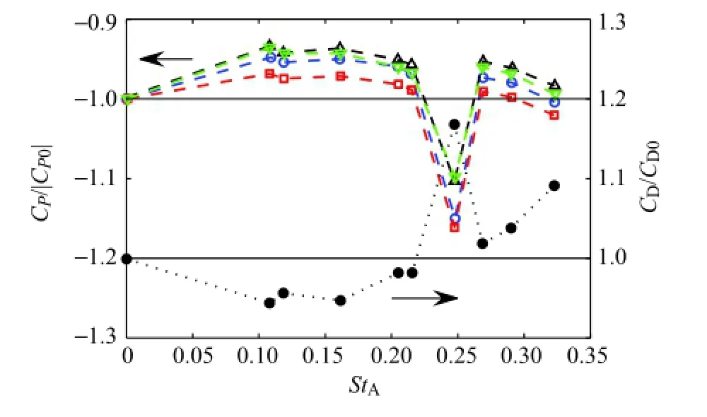
Fig.3.Distributions of the drag coefficient(·)and the pressure coefficient measured at z/H=0.44 and y/H=0.24(◦),0.08(□),-0.08(△)and-0.24(▽)for in-phase actuation(φ=0)with Cµ=0.1%and different actuation frequencies(StA).
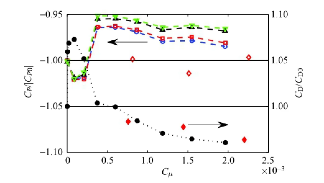
Fig.4.Distributions of the drag coefficient(·)and the pressure coefficient measured at z/H=0.44 and y/H=0.24(◦),0.08(□),-0.08(△)and-0.24(▽)for in-phase actuation(φ=0)with StA=0.16 and different actuation strength(Cµ).The drag(◆)and the averaged static pressure(◇)on the rear wall by Pastoor et al.[8]were also shown for comparisons.
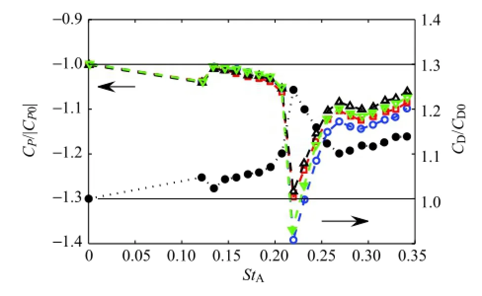
Fig.5.Distributions of the drag coefficient(·)and the pressure coefficient measured at z/H=0.44 and y/H=0.24(◦),0.08(□),-0.08(△)and-0.24(▽)for anti-phase actuation(φ=π)with Cµ=0.1%and different actuation frequencies(StA).
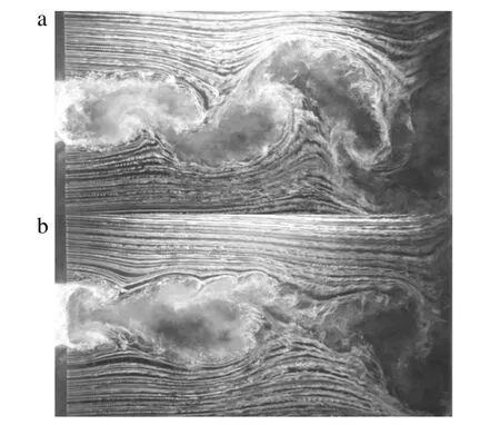
Fig.6.Smoke-wire visualizations of(a)the un-actuated flowand(b)the flowunder actuation of Cµ=0.1%,StA=0.16 andφ=0 behind a D-shaped bluff body for a Reynolds number of 47000.
[1]H.Choi,W.P.Jeon,J.Kim,Control of flow over a bluff body,Annu.Rev.Fluid Mech.40(2008)113-139.
[2]L.N.Cattafesta,M.Sheplak,Actuators for active flow control,Annu.Rev.Fluid Mech.43(2011)247-272.
[3]M.Amitay,A.Glezer,Aerodynamic flow control using synthetic jet actuators,in:P.Koumoutsakos,I.Mezic(Eds.),Control of Fluid Flow,Springer,Berlin,2006,pp.45-73.
[4]L.H.Feng,J.J.Wang,Circular cylinder vortex-synchronization control with a synthetic jet positioned at the rear stagnation point,J.Fluid Mech.662(2010)232-259.
[5]P.F.Zhang,J.J.Wang,L.H.Feng,Review of zero-net-mass-flux jet and its application in separation flow control,Sci.China Ser.E 51(2008)1315-1344.
[6]R.P.Bigger,H.Higuchi,J.W.Hall,Open-loop control of disk wakes,AIAA J.47(2009)1186-1194.
[7]B.Vukasinovic,D.Brzozowski,A.Glezer,Fluidic control of separation over a hemispherical turret,AIAA J.47(2009)2212-2222.
[8]M.Pastoor,L.Henning,B.R.Noack,K.Rudibert,T.Gilead,Feedback shear layer control for bluff body drag reduction,J.Fluid Mech.608(2008)161-196.
[9]P.W.Bearman,Investigation ofthe flowbehind a two-dimensionalmodelwith a blunt trailing edge and fitted with splitter plates,J.Fluid Mech.21(1965)241-256.
[10]H.Park,D.Lee,W.Jeon,S.Hahn,J.Kim,J.Kim,J.Choi,Drag reduction in flow over a two-dimensional bluff body with a blunt trailing edge using a new passive device,J.Fluid Mech.563(2006)389-414.
∗Corresponding author.
E-mail address:gaonan@dlut.edu.cn(N.Gao).
Open-loop flow control
Synthetic jet
*This article belongs to the Fluid Mechanics
 Theoretical & Applied Mechanics Letters2015年1期
- Theoretical & Applied Mechanics Letters的其它文章
- Adjoint-based optimization of flapping plates hinged with a trailing-edge flap
- Numerical simulation of unsteady flows over a slow-flying bat
- Propulsive performance of two-and three-dimensional flapping flexible plates
- Learning from bat:Aerodynamics of actively morphing wing
- A coupled immersed boundary-lattice Boltzmann method and its simulation for biomimetic problems
- A modified criterion for wave-induced momentary liquefaction of sandy seabed
