
Influence of im peller diameter on local gas dispersion properties in a sparged mu lti-im peller stirred tank☆
2015-11-01 02:58YuyunBaoJieYangBingjieangZhengmingGao
Yuyun Bao,Jie Yang,Bingjie W ang,Zhengm ing Gao
State Key Laboratory of Chemical Resource Engineering,School of Chemical Engineering,Beijing University of Chemical Technology,Beijing 100029,China
Keyw ords:Im peller diameter Local void fraction Bubb le size CFD-PBM M ixing
ABSTRACT Vertical distributions of local void fraction and bubble size in air-water dispersion system were measured with a dual conductivity probe in a fully baffled dished base stirred vessel with the diameter T of 0.48 m,holding 0.134 m3 liquid.The im peller com bination with a six parabolic blade disk turbine below two dow n-pumping hydrofoil propellers,identified as PDT+2CBY,was usedin this study.The effects of the im peller diameter D,ranging from 0.30T to 0.40T(corresponding to D/T from 0.30 to 0.40),on the local void fraction and bubble size were investigated by both experimental and CFD sim ulation methods.At low superficial gas velocity V S of 0.0077 m·s-1,there is no obvious difference in the local void fraction distribu tion for all system s with different D/T.How ever,athigh superficialgasvelocity,the system with a D/T of0.30 leads to higher localvoid fraction than system s with other D/T.There is no significant variation in the axial distribu tion of the Sau ter mean bubble size for all the system s with different D/T at the sam e gas superficial velocity.CFD simulation based on the two-fluid modelalongwith thepopu lation balancem odel(PBM)wasused to investigate the effectof the im peller diameter on thegas-liquidflow s.The localvoid fraction predicted by the numericalsim ulation approachwas in reasonable agreement with the experimental data.
1.Introduction
Gas-liquid stirred reactors offer unm atched flexibility and con trol to tailor the fluid dynam ics,which is the reason w hy they are widely usedin the chemical,m ineral,and biochemical industries,wastewater treatm en t,etc.with the increasing industrialscope,large gas-liquid reactors are widely used,so that it becom es more im portant to op tim ize the mixing reactors design.For exam ple,the sizeof reactors like ferm en tors can be as large as 800 m3,leading to the aspect ratio of vessels signi fican tly greater than one,and therefore the requirement of mu ltiple impeller agitators for mixing and dispersion in such vessels[1-4].Du ring the last two decades,m ore and more studies were carried out in system swithm u ltiple im pellers[5-11].The study ofstirred tankswith single or double im pellers has been unab le to meet the needs of the industrial design.In a stirred tank agitated by mu ltiple im pellers,theflow pattern can be significan tly changed for the flowinteractions between the im pellers,heavily dependen t upon the configurational parameters such as im peller spacing andim peller sizing[12].How ever,in stirred tanks with multiple-im peller,the study of the im peller diameter op tim ization is rarely reported.
In large scale industrial gas-liquid reactors,the manu facturing and operational costs are closely related to the optim al design parameters of the im peller,especially the diameter of im pellers.Given the sam e power inpu t of the reactors,the im pellers with sm aller diameter have higher rotational speed and less torque com pared with the larger diameter im pellers.As a result,the size of the gearing box,m echanical seals,andim peller shaft are determined by the choice of the im peller diameter,which becom esvery im portant in large scale reactorswith a volum e up to 800 m3.In recent years,there are som e studies only focusing on the macroscopic gas-liquid dispersion[13,14].Therefore,fu rther research is needed to investigate the relationship between the local gas dispersion properties and the agitator geometrical parameters,to provide the data for op tim izing the design of agitators.
The lim itations in measurement techniques lead to the lack of local in form ation in mu lti-im peller gas-liquid stirred tanks.In recent decades,m ore andm ore measurement techniques were used such as capillary probes,conical hot-film probes and conductivity probes.Am ong those measurement techniques,the conductivity probe is a method suitable for both opaque and dense dispersions.The lim itation is that the size of the probe tip determines the minim um bubb le size which can be detected.
During the last two decades,computational fluid dynam ics(CFD)techniques have been used to calculate hyd rodynam ics in stirred tanks[11,15-20].Com pared with the experimental measurements,CFD technique ism oreefficien tand convenien t to study theeffectofimpeller parameters on the gas-liquid flow.M oreover,CFD technique can also reveal the details that cannot be easily measuredin experiments,such as the distribution of the local void fraction in the im peller discharging region.Thus,the application of CFD simulation has im portant significance in the investigation of gas-liquid flowin multi-phase stirred tanks.
In the present study,a tu rbine-p ropeller com bination consisted of a parabolic blade disk turbine below two dow n-pumping hydrofoil propellers,iden tified as PDT+2CBY,wasused.Them acroscopic gas-liquid dispersion properties are not sufficient to op tim ize the industrially importan t aerated vessels with mu ltiple im peller agitators,so this study is focused on the local gas dispersion properties.Our objective is to obtain the vertical profiles of local void fraction and bubble size distributions in an aerated vessel with mu ltiple im peller agitators.The CFD simulation was also used to predict the local gas dispersion properties in the mu lti-im peller stirred tank.
2.Experimental Setup
All the experim ents were carried out in a dished-bottom cylindrical tank with an internal diameter T of 0.48 mand a liquid-filling aspect ratio H/T of 1.66,as sketchedin Fig.1.The geometry of the tank was exactly the sam e as that usedin our previous studies[5,8-10].Thebottom im peller is a disk tu rbine with six parabo lic b lades,the midd le and upper im pellers are dow n-pumping hyd rofoil propellers,and the confi gu ration is iden tified as PDT+2CBY[Fig.2].The im peller diameter D of the com binations was 0.30T,0.33T,0.37T,and 0.40T.For each impeller com bination,PDT and two CBYs had the sam e im peller diameter.The distance between neighbor im pellers was 0.48T.The clearance between the low est im peller and the base of the tank was 0.33 T.A ring sparger of 0.8D was located 0.25T above the tank bottom and with 27 holes w hose diameter was 2 mm.Four baffles each 0.045 mwide were moun ted 0.005 maw ay from the wall.

Fig.1.Schem atic of the experim ental setup.

Fig.2.Im pellers.
Air and deionized waterwere used as thegas and liquid phases in all experim ents.In order to en large the conductivity difference between deionized water and air,3 ml phosphoric acid was addedin the deionized water.W e measured the in terfacial tension of the water before and after the phosphoric acid was added,and they were 0.07408 and 0.07355 N·m-1,respectively,with the relative error of 0.7%.And the total gas holdups measured before and after the phosphoric added were the sam e,so it is believed that the im pact of phosphoric acid on the coalescence property of water can be neglected.Air passed through three-stage filters before being spargedinto the tank in order to get rid of the im purities in gas.The total gas rates ranged from 5 to 25 m3·h-1,and the corresponding superficial velocities were from 0.0077 to 0.0385 m·s-1,respectively.The liquid bulk temperature was kep t constantly at 25°C.
The distribu tions of the local void fraction and the bubb le size were measured by using a dual electric conductivity probe which was codeveloped with the Institu te of Process Engineering of the Chinese Academ y of Sciences,as show n in Fig.3.

Fig.3.Construction of dual electric conductivity probe.
W hen the probe was in the gas phase,the measurement circuit was open,and a high-voltage signal was the output.W h ile the probe was in the liquid phase,the circuitwasclose,and resultedin a low-voltageoutput.After the signals passed through am plifier,rectifier,and smoothing circuits,square-w ave signals were generated,as show n in Fig.4.

Fig.4.Processed output signals from dual electric conductivity probe.
The gas-to-liquid ratio in a heterogeneous mixture passing through a specific poin t in a reactor was proportional to the ratio between the passage time of all the bubb les and the total sam pling time.The timeaveraged quantity of the local void fraction,ε,was given by

where tgiis the passage time of the i th bubble;nbis the number of bubb les in the sam ple;and t is the total sam pling time.A sam pling rate of 10 kHz was used to collect the data from the sensor probe.In every group of the measurements,m ore than 500 bubb les were detected to obtain the statistically rep resen tative data.And at one measurement,the sam pling time was about 60 s.In our repetitive experim ent,the rep roducibility of the results was reasonab le.The error estim ations between different measurements in one group were less than±5%.Fig.5 show s the arrangement of the measurement poin ts.The probe was moun ted between a baffle and the ad jacent heater,35 mm aw ay from the inner wall of the tank in the radial direction;i.e.,the ratio of the radial position r to the tank radius R was 0.85.There were 30 data collection poin ts in the axial direction of the probe with a distance between consecutive points of 20 mm.

Fig.5.Arrangement of measurement poin ts.
3.Computational Model
In aerated stirred tanks,Eu lerian-Eu lerian app roach was widely used for itsability to handle the system with a wide range of gas holdupin reasonable accuracy.The standard k-ε model was applied with its standard constants(C1ε=1.44,C2ε=1.92,Cμ=0.09,σk=1,σε=1.3)to simulate the con tinuous liquid-phase tu rbu lence.The zero equation model was used with the Sato enhanced eddy viscosity model[21]for the dispersed gas phase.
Several independent physical effects influenced the total interfacial force between the two phases,such as the in terphase d rag force,lift force,wall lubrication force and virtual mass force.According to the analysis of Khopkar et al.[22],the lift force and virtual mass force can beneglectedin an agitated vessel.So only the d rag forceand tu rbu lence dispersion force were consideredin th is paper.The modified Grace model[23]which used a sim ple power law correction to am end the single bubble Grace drag coefficient for high bubble volum e fractions was used to calculate the in terphase d rag force.The turbulent dispersion force was com puted by the Lopez de Bertodano model[24].
M in etal.[11]found that,thesingle averagebubb le diameter(SABD)app roach cannotcorrectly predict the localgasvoid fraction w hether for the high-shear-rate region near the low est im peller or the low-shearrate region near the free surface.The distribu tion of bubb le size was taken into accoun t in order to predict the accurate in form ation of gasliquid stirred tank.The popu lation balance(PB)equations cou ld be used to predict the non-uniform bubb le size distribu tion in aerated stirred vessels.In this study,m u ltiple size group(MUSIG)m odel was used to provide a fram ework in which the popu lation balance method cou ld be incorporatedinto CFD calculations.Population balancesincluding bubble breakup and coalescence effects,p rovide a w ell-estab lished method to calculate the poly-dispersed phases.The MUSIG model assum es that all bubble size groups shared a comm on velocity field but with different slip velocities for different size bubb les.The d rag force on bubb les was calculated based on the local Sau ter mean bubb le diameter.
The general form of the popu lation balance equation was

where BB,DB,BC,and DC,respectively,rep resen t the birth rate due to breakup of larger particles,the death rate due to breakupin to two or more sm aller particles,the birth rate due to coalescence of sm aller particles,and the death rate due to coalescence with other particles.
Thebreak-upm odel,which wasbased on the theory of isotropic tu rbu lence and probability and assum ed binary breakup,was taken from Luo and Svendsen[25].The coalescence model from Prince and Blanch[26]was used.
4.Numerical Methods
The set of equations was so lved numerically using the comm ercial code CFX.The mu ltiple fram es of reference(MFR)method was used to simulate the im peller rotation in the stirred tank.After gridindependence test as show n in Tab le 1,about 1.6 million tetrahed rons and mixed elements were chosen for the en tire calculated region.A scalab le wall function was used to specify the wall boundary conditions.The boundary condition was free slip wall for the gas phase and no slip wall for the liquid phase.The “opening”boundary condition for the tank outlet allow ed the fluid to cross the boundary surface in either direction.W e set the value of the in terfacial tension between the two phases to 0.074 N·m-1.A step function was used to set the initial water level.The experimental data and the validation of the computational results are presentedin the following sections.

Tab le 1 Gridindependence test results
5.Results and Discussion
5.1.Local void fraction distribution
Fig.6 show s the vertical void fraction distribu tions of all system s with different D/T at three different superficial gas velocities.There is an obvious peak of gas void fraction just above the bottom im peller.The gas in troduced from the ring-sparger orifices is discharged radially to the wall and returns along the base of the tank,where the breakup of bubbles dom inates over the coalescence because of the h igh shearing effects of the bottom im peller.W hen the superficial gas velocity is low(VS=0.0077 m·s-1),there is no obvious difference am ong all the system s with different D/T ratios excep t the sm all difference near the bottom im peller.How ever,at the medium superficial gas velocity(VS=0.0253 m·s-1),a slight advantage ofsystem with D/T=0.30 can be observed from the distribution of the local gas void fraction.W hat's more,w hen the superficial gas velocity is high(VS=0.0385 m·s-1),the advantage of the system with D/T=0.30 on the gas void fraction becom es much more obvious.The explanation is as follow s:w hen the superficial gas velocity is low,the agitation speed and shear rate are not the dominan t factors for the local gas void fraction,so there is no obvious difference am ong all the system s;how ever,with the increase of the superficial gas velocity,the sm aller im peller has higher agitation speed and shear rate at the given power inpu t,which benefits the breakup of bubbles.

Fig.6.Influence of D/T on local gas local void fraction distribution at different V S.
In order to evaluate the uniform ity of the gas dispersion in the stirred tank,w e define the variation coefficient CVas follow s:

The sm aller the variation coefficient CV,the more uniform the gas dispersion in the stirred tank.Tab le 2 show s the variation coefficient of local void fraction.

Tab le 2 Variation coefficients of local void fraction
It can be seen that at low and medium superficial gas velocity,the value of CVhas no obvious difference.W hen the superficial gas velocity is high,the variation coefficient of the sm aller im peller is obviously sm aller(m ore uniform local void fraction)than that of bigger ones.
The im peller diameter and superficialgas velocity are two dom inan t factorsaffecting theaverage localvoid fraction εalong the verticaldirection.In order to obtain the quan titative relationship between the average local void fractionand these twofactors,the average void fractioncou ld be correlated by Eq.(5):

Com pared with the experim ental results,a quantitative correlation is obtained as

It can be seen that the power exponen t of D/T is negative,reflecting the reduced average void fraction for the larger im peller diameter.Eq.(6)also show s that,the absolute exponent of D/T is larger than that of the superficial gas velocity which means that the effect of D/T on average void fraction is greater than that of the superficial gas velocity.
5.2.Vertical profile of bubble size
During the measurements of the bubble size,the bubble will not alw ays be penetrated at its axis by the probe tip.The chord length was sm aller than the largest vertical dim ension of the bubb le.Liu and Clark[27]p roposed the reconstruction model which derived the relationship between the bubble chord length distribu tion and the bubb le size distribution.The Sauter mean bubble size d32was calculatedin the sam e w ay as our previous work[5,10].
Fig.7 show s the distributionsof the Sau ter mean bubble size,d32,for all system sofdifferent D/T atdifferentgassuperficialvelocities.There is no significan t variations in the Sauter mean bubble size in the axial direction w hen VSis the sam e.M eanwhile,w e can find that the higher the VS,the bigger the d32value.W hen VSis as lowas 0.0077 m·s-1,the gas holdupis low which is not beneficial for sm all bubbles to coalesce.There is a minim um bubble size near the bottom im peller for all system s with different D/T because the tu rbu lence kinetic energy from the radialbottom im pellerhelps in breaking up thebubblesinto sm aller ones.

Fig.7.Influence of im peller diameteron Sauter mean bubble size distribution at different V S.
d32,isalso influenced by both the im peller diameter and the gas rate.The average Sau ter mean bubb le size of all measured values at r/R=0.85,cou ld be correlated by

Based on theexperim entalresults,theequation cou ld be obtained as

Eq.(8)show s the negative power exponen t for D/T,which im plies that the bubb le size decreases a little with the increase of D/T.It also can be seen that the abso lu te exponen t of the superficial gas velocity is larger than that of D/T whichm eans the effectof superficialgasvelocity onis greater than D/T.
5.3.Comparisons of simulations with experim ents
A CFD com putational model was established to study the gas-liquidflow generated by a mu lti-im peller configu ration with different im peller diameters in a stirred vessel at the sam e power inpu t(Pm=1 W·kg-1)and low superficial gas velocity(V s=0.0077 m·s-1).
The predicted vector plots for the liquidflowfield are show n in Fig.8 for D/T=0.30,0.33,0.37 and 0.40,and the flow patterns are all similar.The bottom radial-flowim peller PDT pum ps the fluid to the wall,and the jetting fluid flow s along the ellip tical tank bottom back tow ards the im peller.Tw o sm all-scale axial circu lations are in the central region of the tank,caused by the com bined effect of the two dow n-pumping axialCBY im pellers.Harvey etal.[12]suggested thata change of the impeller size in a mu ltiple im peller configu ration cou ld lead to the variation in flowin teractions between mu ltiple im pellers,greatly affecting the fluid circu lation in the vessel,differing from the observations in our case.The rotational speed andim peller tip velocity corresponding to the given power input of 1 W·kg-1in the experiment are show n in Tab le 3.It can be seen that,given the sam e power input and superficial gasvelocity,the sm aller the im peller diameter,thehigher the rotational speed and the tipim peller velocity.
Fig.9 show s the predicted turbu lence kinetic energy(TKE)p rofiles from the center to the wall of the tank in the location where thebottom im peller is installed.All profiles for different D/T show that the maxim um TKE value is located at the im peller tip where Vtipis the highest.As w e expected,the higher the Vtip,the larger the maxim um TKE,so that the sm aller D/T has the higher TKE at the tip of the im peller.However,at the place near the wall,the sm aller im peller has low er TKE.It can be explained that the distance between the im peller tip and the tank wall is sm aller for the lager im peller so that TKE can stay at a relatively higher level com pared with the sm aller im peller.The high TKE con tributes to the break-up of bubb les,leading to the sm aller bubb le size as show n in Fig.7(a).At the heigh t of the bottom im peller,the system with bigger im peller diameter has sm aller bubble size.
Fig.10 show s the simulated and experimental local gas void fractions at the sam e power input Pm=1 W·kg-1and sam e VS=0.0077 m·s-1for D/T=0.30,0.33,0.37 and 0.40,and the reasonab le agreement is observed.The com putational model can successfully capture the peak of the local gas void fraction distribu tion near the bottom im peller in this mu lti-im peller system,but its values are low er than the experim ental ones.There are two reasons for the discrepancies:first,the com plicatedfluidflowin thissystem with three strongly in teracting im pellers cannot be accurately predicted by the k-ε model;second,the breakup and coalescence models usedin our simulation were originally proposed for a bubb le co lum n.Those models have lim itations while being applied to the stirred tank.

Fig.8.Liquid velocity vectors(P m=1 W·kg-1).
The predicted local void fraction distribu tions at the mid-baffle plane in the stirred tanks with different D/T are show n in Fig.11.A high void fraction area exists in the region near the bottom im peller due to high shear rate here,leading to the peak value near the bottom im peller as show n in Fig.6(a).Fig.8 show s that,with the D/T increasing from 0.30 to 0.40,the evidently increased pumping capacity of the impeller leads to an increase in fluid pumping dow nw ards toform a large-scaleaxialcircu lation at the sam e power inpu t.The localvoid fraction distributionsbellow them iddle im peller increase with the increase of D/T though the bigger im peller has sm aller rotational speed at the sam e power input as show n in Table 3.

Tab le 3 Rotational speed and corresponding im peller tip velocity at given power input of 1 W·kg-1

Fig.9.Tu rbu lence kinetic energy profiles from bottom im peller to thewallin them easurement plane.
6.Conclusions
The effectof im peller diameteron the localgasdispersion properties at different superficial gas velocities in mu ltiphase stirred tank was investigated with both experimental and computational methods in a vessel of 0.48 mdiameter agitated by the multi-im peller configurations with D/T of 0.30,0.33,0.37,or 0.40.It cou ld be summ arized as follow s:
(1)with the increase of the superficial gas velocity from VS=0.0077 m·s-1to VS=0.0385 m·s-1,the tendency that the sm aller D/T im pellers cause larger local gas void fraction becom es more obvious.As expected,the local void fraction increases with the increase of VS,and the quan titative correlation ε =50⋅65( D/T)-0⋅81VS0⋅69applies in the range of D/T=0.30 to 0.40 and V s=0.0077 to 0.0385 m·s-1.
(2)There is no significan t variation in the axial profiles of the Sau ter mean bubb le size for all the system s with different D/T for a given superficial gas ve locity.How ever,thequan titative result=6⋅75( D/T)-0⋅09VS0⋅12show s that the Sau ter mean bubb le size decreases a little with the increase of D/T andincreases with the gas superficial velocity.
(3)A CFD computational model was estab lished to study the gasliquid flow generated by a multi-im peller configuration in a stirred vessel to help us to understand the effect of the im peller diameteron the distributionsof localvoid fraction.The predicted local void fraction at superficial gas velocity of 0.0077 m·s-1in the stirred vessel is in reasonab le agreement with the experimental data.The predicted turbu lence kinetic energy profiles help us to understand the measured distribu tion of the bubb le size and local void fraction.
Nomenclature

Fig.10.Experim ental and simulated vertical distributions of local void fraction.
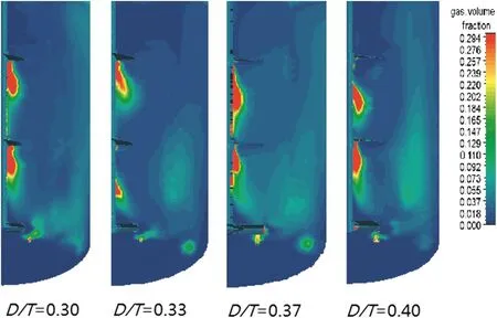
Fig.11.Local void fraction distribu tions(P m=1 W·kg-1).
 Chinese Journal of Chemical Engineering2015年4期
- Chinese Journal of Chemical Engineering的其它文章
- Accurate level set method for simulations of liquid atom ization☆
- Heat transfer augmentation in a circular tube with winglet vortex generators☆
- Pow er dem and and mixing performance of coaxial mixers in a stirred tank with CMC solution
- CFD simulation of high-temperature effect on EHD characteristics in a wire-plate electrostatic precipitator☆
- Em u lsion liquid mem brane for selective extraction of Bi(III)
- Adsorption of zinc onto anionic ion-exchange resin from cyanide barren solution☆