
Accurate level set method for simulations of liquid atom ization☆
2015-11-01 02:58ChangxiaoShaoKunLuoJianshanYangSongChenJianrenFan
Changxiao Shao,Kun Luo*,Jianshan Yang,Song Chen,Jian ren Fan
State Key Laboratory of Clean Energy Utilization,Zhejiang University,Hangzhou 310027,China
Keyw ords:Com putational fluid dynam ics Level set method Spray atom ization Interface cap ture Breakup
ABSTRACT Com putationalfluid dynam ics isan efficien tnumericalapp roach for sp ray atom ization study,but it ischallenging to accurately capture the gas-liquidinterface.In this work,an accurate conservative level set methodis in troduced to accurately track the gas-liquidinterfaces in liquid atom ization.To validate the capability of thismethod,binary drop collision and dropim pacting on liquid film are investigated.The results are in good agreement with experiment observations.In addition,p rim ary atom ization(swirling sheet atom ization)is studied using this method.To the swirling sheet atom ization,it is found that Rayleigh-Taylor instability in the azimuthal direction causes the primary breakup of liquid sheetand com plex vortex structuresare clustered around the rim of the liquid sheet.The effects of centralgasvelocity and liquid-gasdensity ratio on atomization are also investigated.This work lays a solid foundation for further studying the mechanism of spray atomization.
1.Introduction
In most of the propulsion devices,fuel is in jectedinto com bustion cham ber in the form of liquid.It subsequen tly undergoes the process of atom ization,evaporation and com bustion in order to generate power for the engine.Since the atom ization process governs the liquid droplet diameter distribution,it strongly affects both the evaporation and com bustion processes.Theatom ization can be dividedin to primary atom ization and secondary atom ization.primary atom ization is thep rocess wherein liquid jet breaks intofilam ents and droplets due to interaction with am bien t air.Secondary atom ization is the process whereinfilam en ts and droplets con tinue to break in to even sm aller droplets.For the secondary atom ization,som e models have already been proposed,such as TABm odel,WAVEm odeland so on.How ever,the primary atom ization is hard to investigate.The measurement of atom ization is difficu lt especially for the dense sp ray zone,bu t the computationalfluid dynamics(CFD)hasp roven to bea promisingmethod for atom ization study.
Nevertheless,CFD-based numerical simulation has difficu lties in dealing with atom ization[1].Firstly,the gas-liquidin terface is hard to locate.There are two main catego ries of methods for locating the in terface,that is,the in terface tracking method andin terface capturing method.In terface tracking methodis based on the Lagrange fram ework,in w h ich the in terface is hand led as many particles,such as the Fron t-tracking app roach.The main lim itation of this methodis the lack of autom atic topology modification and the dif ficu lty in parallelization.In terface cap tu ring methodis based on the Eu ler fram ework,such as vo lum e of fluid(VOF)method and level set method(LSM).VOF method tracks the vo lum e fraction of liquidin each cell and has good mass conservation.How ever,since the interface is not smooth,a specific advection schem e is required,w h ich adds constrain ts on the accu rate VOF method.Additionally,the interface norm al and curvature are difficu lt to calculate.In the LSM,the in terface is representedim plicitly as the zero level set of a continuous function.It is conven ien t to calculate the in terface norm al and cu rvature and the in terface can be cap tured with su fficien t resolution.The level set method has been used to many applications,such as[13,30,31].Nevertheless,this method has no conservative properties inheren tly,that is,the liquid vo lum e can be lost du ring the evo lu tion of in terface.Second ly,sm all length and time scales dem and much cost of computation.The large eddy in the gas or liqu id phase is several orders of magn itude bigger than the sm all ones.At the sam e time,droplets w hose diameters may be sm aller than the Ko lm ogo rov scales must also be distingu ished.Th ird ly,the discretization of the Navier-Stokes equations becom es difficu lt because of the discon tinu ity in material properties across the in terface,especially for the large ratio in density and dynam ic viscosity.The o ther challenges in the simulation of atom ization include the singu larity of surface tension that just exists on the in terface,the com plexity of in teraction between atom ization and turbu lence,and the frequen t topo logical changes.
LSM has many advan tages over VOF bu t the mass conservation is not satisfactory.Th is d raw back will seriously affect the accu racy of in terface cap tu ring.Recently,som e app roaches have been proposed to im prove the mass conservation of level set method.En righ t et al.[2]p roposed the particle leve l set method,w h ich uses massless marker particles to update the in terface location predicted by an Eu lerian transpo rt equation.It was demonstrated that the particle level set method has great improvement over the original LSM in mass conservation,bu t the procedure of error correction and particle reseeding is com plicated and the computational cost is h igh due to the large number of massless particles in each ce ll.Sussm an et a l.[3]and M enard et al.[4]developed the coupled level set and VOF(CLSVOF)method to enhance the mass conservation by com bining the advan tages of two methods,i.e.good mass conservation and easy surface cu rvature descrip tion.How ever,th is method so lves bo th advection equations and uses sm all time steps,leading to h igh com putation cost.Herrm ann[5]developed a balanced force refined leve l set grid(RLSG)method,which reduces the numerical errors in level set function advancement and re-in itialization through the refined grid.Th is method has good e fficiency in computation and good mass conservation bu t it is difficu lt to implement.An accu rate conservative level set method proposed by Desjardins et al.[6]has good mass conservation properties by using hyperbo lic tangen t function andis easy to implement.
In the present study,the accu rate conservative level set methodis fu rther validated and applied to study fundamental phenom ena in sp ray atom ization.The liquid jet and crossflow have been ex tensively studied,as men tionedin[19-26].How ever,the swirling liquid atom ization has not been reportedin the literature,which is applied to the aero engine and rocket propeller extensively and dem ands thorough study.In th is paper,the conservative level set methodis applied to the simulation of swirling liquid sheet atom ization.Th is preliminary work is to reveal the mechan ism of swirling liqu id sheet atom ization.The effects of central gas velocity and density ratio to atom ization are also discussed.
2.Numerical Methods
2.1.Incomp ressible Navier-Stokes equations
To describegas-liquidflow,the incom pressible Navier-Stokesequations are in troduced:
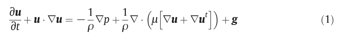
where u is velocity vector,ρ is density,pis pressure,g isgravity acceleration,and μ is dynam ic viscosity.
The con tinuity equation is
In each phase,m aterialp ropertiesare constant.Them aterialproperties jum pat the in terface,which can be rep resented asThe velocity at the in terface is con tinuous,The pressure at the in terface is discontinuous,

where σ is surface tension,κ is curvature,and n is unit norm al vector.
2.2.Accurate conservative level set method
In the level set method,the in terface is usually defined as the isosurface of a smooth function.This function is defined as signed distance function:

Here φ(x,t) > 0 for liquid phase,φ(x,t) < 0 for gas phase and φ(x,t)=0 at the interface.This function has the advan tage to calculate the norm al and cu rvature of the in terface because|∇φ(x,t)|=1.The norm al and curvature can be expressed as

How ever,the signed distance function does not guarantee the mass conservation ofeach phase,and the volum eof liquidm ay change du ring the advancement of the signed distance function.This will obviously bring numerical errors.Hence,the hyperbo lic tangen t function proposed by Olsson and Kreiss[7,8]is in troduced fo llowing the study of Desjardins et al.[6]:

where ε is the thicknessof the profile.The interface is locatedin the isosurface of ψ=0.5.
It is show n in Fig.1 along with the liquid vo lum e fraction w hen ε=0.01.
From Fig.1 it can be found that the hyperbolic tangent function is alm ost the sam e as a Heavyside function.Furtherm ore,the in tegral of the hyperbo lic tangen t function isequalto the liquid volum ew henεgoes to zero,i.e.,

where H is Heaviside function and d V is volum e element.This equation means that conservation of hyperbo lic tangen t function is equivalen t to conservation of liquid volum e.
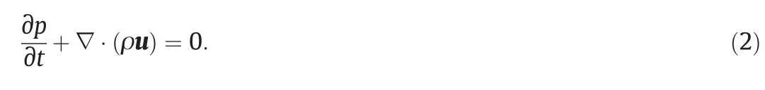
The equation of level set function advection is
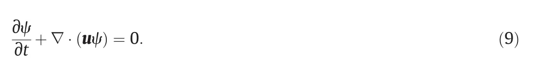

Fig.1.Hyperbo lic tangen t function(dotted line)and liquid vo lum e fraction(solid line)with interface located at x=0.
How ever,the level set profile will deteriorate during the transport of the level set function.Therefore,a re-initialization process is needed.The re-initialization equation is[7,8]:

whereτisa pseudo time.Solving Eqs.(9)and(10)allow s foradvection of the interface by the fluid velocity,p reserves the hyperbolic tangent profi le,and main tains discrete conservation of ψ over the com putational dom ain.
High order upstream central(HOUC)schem e[6]is adoptedin this work.n th-order level set transport schem e can be expressed as

The two term s in the re-initialization Eq.(10)can be expressed as
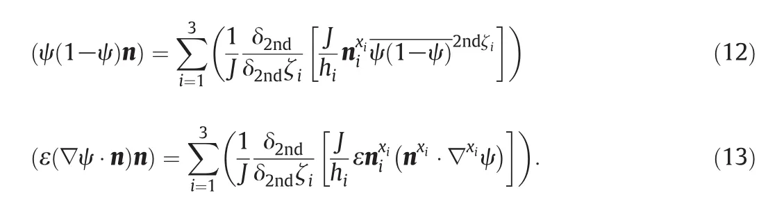
Accu rate solution of Eq.(9)is perform ed using second order central differencing schem e for spatial discretization and second order sem iim plicit Crank-Nico lson time in tegration.The velocity and pressurefields are computed using a pro jection method[6].The pressure jum pat the interface is discretized using ghost fluid method(GFM).
The procedu re of th is methodis briefly given as fo llow s:Firstly,using time in tegration,advance the level set scalar by solving Eq.(9).Then,compute the in terface norm al and curvature using Eqs.(5)and(6).Finally,perform the re-in itialization step using Eq.(10).The present sim ulation is based on the in-house code and the every stepis not stopped until the velocity is convergen t.The gridindependence test is conducted through increasing the grid size.
3.Numerical Validations
This method has been validated by Desjardins et al.[6]using Zalesak's disk,circle in a two dim ensional velocity field and sphere in a three dim ensional velocity field,but the velocity fields are all know n in these cases and no practical cases were tested.Tofu rther validate the capability in managing actual prob lem for th is method,binary drop collision and dropim pactingon liquidfilm are studied,thatalw ays occur in sp ray atom ization.
3.1.Binary drop collision
The regim e of coalescence and separation of binary drop collision wasstudied by Qian and Law[9].They found five collision modes at different gas environm en ts using water and hyd rocarbon droplets.Thefive modes are coalescence after minor deform ation,bouncing,coalescence after substan tialdeform ation,coalescence follow ed by separation for near head-on co llision and coalescence fo llow ed by separation for off-center collision.Ashgriz and Poo[10]studied the binary drop collision of different diameters and found two different separation modes,that is,reflexive and stretching separations,corresponding to head-on and off-center co llision.The binary co llision theoretical model was also proposed.Tanguy and Berlenon t[11]used LSM to simulate the binary drop collision and got excellent agreement with experim ent.A new drop co llision model was proposed by Ko et al.[12].This model cou ld predict the number of satellite droplets,the velocity and sizes of droplets.This model was com pared with experiment to test its accuracy.
This section aim s at simulating three-dim ensional binary drop co llision in order to cap ture the main phenom ena in the co llision and com pare with experiment.The experiment[10]is used here.The properties of liquid and gas are listedin Tab le 1.In this case,two binary drops of diameter 800 μm do the head-on co llision.The relative velocity is 1.65 m⋅s-1and the W eber number is We==30.The dom ain is 2 mm×4 mm×2 mm and the gridis 64×128×64,which satisfied mass conservation in[11].The present simulations on W e=30 and W e=40 are show n in Figs.2 and 3,respectively.
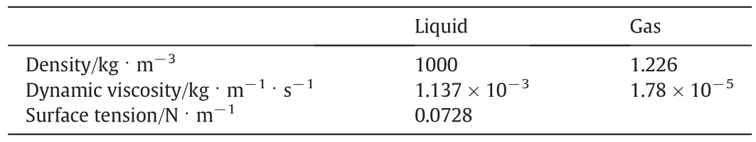
Tab le 1 The material properties of liquid and gas

Fig.2.Drop collision at W e=30(above:experim ental results[10];below:the present sim ulations).
As can be seen from Figs.2 and 3,the levelset resultsagreew ellwith the experim ental observations.W hen the W eber number is sm all,the two drops can developinto a flying saucer shape.Then it com es into being the shape of torus w hen the inertia force decreases.Later,bounce appears and two drops go aw ay from each other.Tw o separate drops form w hen inertia force overcom es the surface force due to surface tension.For the case of biggerW eber number,ligam en t form s between the two drops,and the ligam en t separates from the two drops and form s satellite drop between two primary drops.The simulations catch w ell the phenom ena that appear in the experim ents.
As men tionedin[11],quan titative comparisons can be biased by a lack of experimental operating conditions or detailed measurement data.Here w e just com pare ou r results with experiment[9]and simulation[14]for the transition between coalescence regim e and separation regim e for drop head-on co llision.The result is show n in Fig.4.

Fig.3.Drop collision at We=40(above:experim ental results[10];below:the present simulations).

Fig.4.comparison between numerical and experimental results for the transition between coalescence and separation in Oh-We space for drop head-on collision.
The Ohnesorge number is defined asTheagreement between our numerical resultsand experim ental results issatisfactory and confirm s that the present levelsetmethodis an accurate tool to deal with the drop collision.
Fig.5 displays the time evolu tion of the drop volum e fraction for binary drop collision.The mass loss is about 3%for We=30 case and about 4%for We=40 case,indicating that the mass conservation of the methodis reasonable.
3.2.Dropim pacting on liquid film
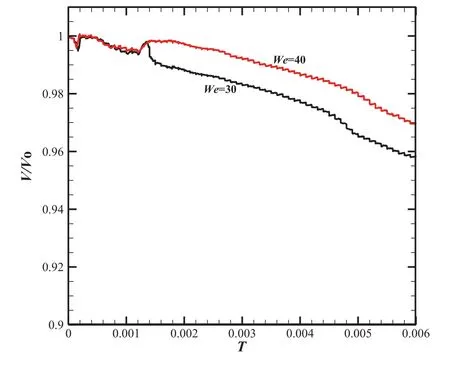
Fig.5.time evolution of volum e fraction for binary drop collisions in Figs.2 and 3.
There are many experiments and simulations about the dropim pacting on liquid film.Cossali et al.[15]studied the structure of crow n form ed w hen single dropim pacts on liquid film.The heigh t and diameter of crow n were analyzed for different W eber numbers and non-dim ensionalheigh tsoffilm.Lee etal.[16]used LSM to simulate the experim ent done by Cossali et al.[15].It was found that the data coincided with experiment at early time but didn't long after,which indicated thatdropim pacting on liquidfilm took on symmetry atearly time while it presented three-dim ensional nature after certain time.Liang et al.[17]studied the im pact of viscosity and surface tension on the crow n using CLSVOF method and revealed the mechanism of neck jet of dropim pacting on liquid film.The breakup and coalescence of dropim pacting on liquidfilm were discussed using PIV technology by Kassim and Longm ire[18].
In order to test the presentmethod's capability ofcap turing com plex phenom ena,the case of dropim pacting on liquid film on a solid surface is studied.The material properties are as the sam e as in Tab le 1.The com putational dom ain is 30 mm×15 mm and the gridis 512×256.The drop of diameter 3.8 mm is in itially at the surface of the film of heigh t 3 mm.The drop velocity is 2.4 m·s-1.The numerical results are show n in Fig.6.
It is obvious to see that the crow n or the splashing lam ella form s in Fig.6.The rim form sat the top ofcrow n at t=0.001 sbecauseofsurface tension.The rim gradually escapes from the crow n at t=0.002 s and then develops in to secondary droplets.The heigh t of crow n gradually increases and diameter magnifies.The rim,crow n,and secondary droplet are all cap turedin our simulation.
The evolution of dim ension less crow n radius r/D with time tV/dis quan titatively com pared with the numerical results in[19].As show n in Fig.7,the trend of the radialgrow th of the splashing lam ella isconsisten twith each other although the parametersare differentbetween the two simulations.
4.Applications to primary Atom ization
4.1.Swirling liquid sheet atom ization
primary atom ization offers a rich physical phenom enology which is still poorly understood.with the increase of computer capability,CFD numericalsimulation ofp rim ary atom ization hasbeen developed rapidly in recent years,such as jet atom ization[20-24]and crossflow atomization[25-27].How ever,there is little study on swirling liquid atom ization.In this section,the swirling liquid sheet atom ization in lam inar regim e is investigated using the accurate level set method.
The sketch map of the swirling liquid sheet atom ization is show n in Fig.8.The gas is in jected at the center with the nozzle of diameter Din.The swirling liquid flow s coaxially with the annu lar gap thickness(Dout-Din)/2.The detailed parameters in this case are listedin Table 2.
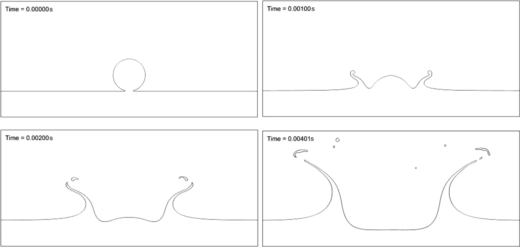
Fig.6.The in terface evo lu tion of dropim pacting on liquid film(black line rep resen ts the in terface).

Fig.7.comparison ofsimulation results about radialgrow th of the splashing lam ella Fig.6.
4.2.Interface evolution of the swirling sheet atom ization
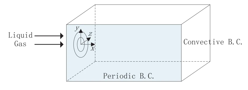
Fig.8.Sketch of the swirling sheet atom ization.
Fig.9 show s the in terface evo lu tion of the swirling liquid sheet atom ization.The in itial liquidis set to the shape of sem i-sphere mem b rane with th ickness 1/2(Dout-Din).The liqu id film ejecting from the annu lus is lam inar flow.The time is non-dim ensioned by Dout/Vl,that is,T=tVl/Dout,where V1is the axial velocity of liquid.At an early time of T=1.50,the tip mush room shape is observed.A recircu lation region appears beh ind the jet fron t andinstan taneous b reakup occu rs from the mush room edge.with the evo lu tion of atom ization,liquid sheet is observed.As no distu rbances are added upstream,the liquid sheet keeps its sm oo th surface to a certain distance.It is observed that transverse azim u thal pertu rbation occu rs in the tip of liqu id sheet at T=3.00.Villerm aux et al.[28]have proposed that transient acceleration in the direction norm al to the liqu id at the rim s triggers a Ray leigh-Tay lo r instability,w h ich produces the azim u thal pertu rbation.The transverse azimuthal pertu rbation grow s in am plitude producing ligam en ts at the w ave crests at T=3.75.Later,these ligam en ts are stretched and droplets are produced at the tips of ligam en ts.
4.3.The relationship between interface and vortex structure
The vortex structures characterized by the Q criterion are show n in Fig.10.The secondinvariant of the velocity gradien t tensor defined asQ=(AijAij-SijSij)/2 is used to visualize the vortex structures,where Aijand Sijdenote antisymmetric and symmetric parts of the velocity gradien t tensor,respectively.It is observed that the com plex vortex structures are main ly clustered around the fron t of liquid sheet.The torusshape and ligam en t-shape structures are seen from these com plex structures.

Tab le 2 Summ ary of parameters for swirling liquid sheet atom ization
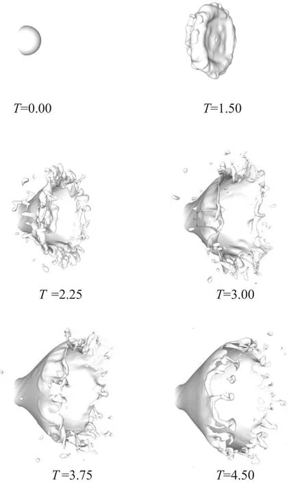
Fig.9.Interface evolution of swirling liquid sheet atom ization.
In the fron t of liquid sheet,ligam en ts and droplets form ed undergo invo lu te movement,which are con trolled by inertial force,centrifugal force,aerodynam ic force and surface tension.The local flow patterns,associated with velocity gradien t,have an effect on the deform ation and movements of ligam ents and droplets.The in terface and vortex structures characterized by the Q criterion are sim u ltaneously show n in Fig.10.It is clear to see that torus-shape vortex structures w arp the droplet,and the filamentary vortex tubes are along with the rim of liqu id sheet and a large number of vo rtex tubes are aligned with axis.
Du ring the movement of liquid sheet,an ti-parallel vortex pairs in Fig.11 occu r in the sidesof the top of liquid sheet.In theoutsideof liquid sheet,the vortex is coun terclockwise,while the vortex is clockwise inside of liquid sheet.It is obvious that vortex inside is larger than that outside,which indicates that the two eddiesarenotequalin the capability of en trainm en t.Therefore,the liquid sheet tends to bend to inside zone because of the strength of vortex inside.Moreover,the intense shear force around the liquid sheet shou ld lead to the breakup of bu lk liquid.

Fig.10.Interaction between interface and vortex structures characterized by Q criterion(color for Q value).
4.4.The effect of central gas velocity on atom ization
similar to Ku lkarn i et al.[29],the different central gas velocity is perform ed to dem onstrate the effect of central gas velocity on atomization.As show n in Fig.12,for large central gas velocity,the central air pu lls the liquid sheet more in tensively,so that the cone ang le is sm aller for larger central gas velocity,which accords with the experimental result by Ku lkarni et al.[29].In addition,it is alm ost the sam e for the breakuplength,which is defined as the distance between the orifice exit and the location for liqu id sheet breakup.It is apparen t that the th ickness of liquid film decreases with increasing distances from the orifice exit and beyond a certain distance,the liquid sheets begin to disin tegrate.

Fig.12.The interface location for different central gas velocity.
4.5.The effect of liquid-gas density ratio on atom ization
For different liquid fuelapplied to the com bustion,it isapparen t that properties of liqu id fuels can have effect on atom ization.In order to dem onstrate the effect of liquid-gas density ratio on the atom ization,the density of gas is changed.As show n in Fig.13,the liquid sheet is more w rinkled for little liquid-gas density ratio.This may be attributed to the stronger aerodynam ic force to the liquid sheet.In addition,the breakuplength is shorter for ρl/ρg=8.
5.Conclusions
In this study,the accurate level set methodis applied to the com putation ofgas-liquidin terface cap ture,which isvalidated using two cases of simulation.Simulations of binary drop co llisions are w ell in agreement with experimental results and the critical W eber number accords to that conducted by Qian&Law[9].The simulation of dropim pacting on liquid film cap tures the sm all structures of liquid such as rim,crow n,and secondary droplet.

Fig.13.The interface location for different liquid-gas density ratios.
The swirling liquid sheet atom ization is studied to reveal som e phenom ena about primary atom ization.From the in terface evo lu tion,Ray leigh-Tay lo r instability in the azim u thal direction causes the primary b reakup of liquid sheet.It is found that com plex vo rtex structures are clustered around the rim of the liqu id sheet.The an ti-parallel vo rtex pairs are also observed near the rim of liquid sheet and the liquid sheet tends to bend to inner side since strong recircu lation zone.In addition,the presence of the central air pu lls the liqu id sheet tow ard the sp ray ax is.The liquid sheet is mo re w rink led for higher gas density.
The developm en t show n in th is work is not su fficien t to reveal the mechanism of primary atom ization.In addition,the droplet diameter distribu tion is not includedin present simulation.The quantitative analysis needs to be conducted fu rther to consider the parameters that affect the primary atom ization.In summ ary,the accu rate level set method presented here shall be a promising too l to study the primary atom ization.
Nomenclature

Subscripts
 Chinese Journal of Chemical Engineering2015年4期
- Chinese Journal of Chemical Engineering的其它文章
- Heat transfer augmentation in a circular tube with winglet vortex generators☆
- Influence of im peller diameter on local gas dispersion properties in a sparged mu lti-im peller stirred tank☆
- Pow er dem and and mixing performance of coaxial mixers in a stirred tank with CMC solution
- CFD simulation of high-temperature effect on EHD characteristics in a wire-plate electrostatic precipitator☆
- Em u lsion liquid mem brane for selective extraction of Bi(III)
- Adsorption of zinc onto anionic ion-exchange resin from cyanide barren solution☆