采用数值分析的压痕法识别陶瓷材料断裂韧性的精度问题研究
王家梁,马德军,孙 亮,肖富君
(1.装甲兵工程学院机械工程系,北京 100072;2.总装备部南京军事代表局,江苏 南京 210024)
采用数值分析的压痕法识别陶瓷材料断裂韧性的精度问题研究
王家梁1,马德军1,孙 亮1,肖富君2
(1.装甲兵工程学院机械工程系,北京 100072;2.总装备部南京军事代表局,江苏 南京 210024)
采用虚拟裂纹闭合法的基本原理对基于数值分析的压痕法识别陶瓷材料断裂韧性的精度问题进行研究,分析比较了3种典型基于数值分析的压痕法计算公式对陶瓷材料断裂韧性的测试精度.结果表明,Tang公式和Lee公式所测断裂韧性值与理论计算值的最大误差均随比功增加而增大,其最大误差分别为193.39%和81.99%;Hyun公式除对弹性模量E=70 GPa、We/Wt=0.7的材料测试误差高达-75.59%之外,其余材料范围测试误差均处于30.65%之内;相比Tang公式和Lee公式,Hyun公式明显具有较高的测试精度.本文工作为合理使用压痕法准确获得陶瓷材料断裂韧性值以及为下一步研究建立具有测试精度高、适用范围广的新型断裂韧性测试方法提供了一定的理论基础.
数值分析;压痕法;陶瓷材料;断裂韧性;比功
压痕法作为陶瓷材料断裂韧性的常用测试方法,其相比于表面裂纹弯曲法(SCF)[1-2]、山形切口梁法(CNB)[3-4]、单边预裂纹梁法(SEPB)[5-6]、单边切口梁法(SENB)[7-8]具有试样尺寸小、测试效率高、无损等明显优势,一直以来受到国内外学者的广泛关注[9-15].以往传统压痕法的理论基础和公式建立系基于半解析与半经验方法的联合,在导出半解析半经验公式过程中往往对应力场的分析过于简单,导致断裂韧性计算结果偏差较大.因此,近年来,部分学者考虑采用有限元数值分析的方法得到被压材料的应力场,从而试图准确地建立材料压入响应与断裂韧性的内在关系.
目前,有限元数值分析方法计算陶瓷材料断裂韧性值主要有2种途径:第一种途径系通过叠加原理(superposition principle)间接计算获得[16-18],即被压材料在压头载荷作用下,裂纹尖端的应力强度因子等于无裂纹时该压头载荷在裂纹处产生的内应力反作用于没有压头载荷时裂纹表面所对应的应力强度因子;第二种途径系通过粘结单元(cohesive elements)直接计算获得[19-24],即通过粘结单元设置合理的断裂准则用以模拟两部分之间的黏性连接,将其预先设置于裂纹开裂面可以模拟材料的断裂.近几年,基于上述2种数值分析方法获得的压痕公式形式较多,但究竟选用何种公式能够获得准确的断裂韧性值至今尚无定论.
本文基于虚拟裂纹闭合法[25]的基本原理对基于数值分析的压痕法识别陶瓷材料断裂韧性的有限元模型进行计算,以此为基础,分析比较3种典型基于数值分析的压痕法计算公式(Tang公式[17]、Lee公式[21]、Hyun公式[24])对陶瓷材料断裂韧性的测试精度,以期为合理使用此类方法测试陶瓷材料断裂韧性提供理论依据和技术基础.
1 几种典型基于数值分析的压痕法介绍
大量研究表明[13-15,17,26-28],压痕法测试陶瓷材料断裂韧性过程中,材料沿压痕对角线方向会形成2种裂纹开裂形式,即径向裂纹(Radial Crack,RC)和半硬币状裂纹(Half-Penny Crack,HPC),如图1.
2008年,Tang等[17]针对Vickers压头压入陶瓷材料测试其断裂韧性建立了三维有限元模型,通过量纲分析和叠加原理,分别建立了针对HPC和RC的2种开裂形式的陶瓷材料断裂韧性KIC计算公式,从而获得了基于数值分析的压痕法测陶瓷材料断裂韧性的Tang方法,其具体公式如下.
对于HPC裂纹开裂形式:
图1 压痕法测试陶瓷材料断裂韧性的2种裂纹开裂形式
Fig.1 Schematic diagram of indentation method to determining the fracture toughness of ceramic materials
(1)
对于RC裂纹开裂形式:
(2)
其中:E和σy分别为材料弹性模量和屈服强度,c和a分别为实际裂纹开裂半长和压痕对角线半长,l=c-a,多项式系数取值如表1.
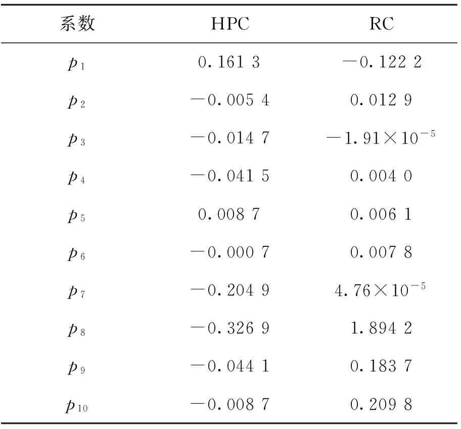
表1 Tang公式各系数取值
2012年,Lee等[21]采用cohesive interface elements对四棱锥刚性压头压入脆性材料的压头几何形状、压入载荷、cohesive参数、被压材料参数分别对裂纹系统的影响进行研究,并基于Lawn-Evans-Marshall模型提出了由压入载荷、裂纹长度、硬度、弹性模量和压头几何形状识别脆性材料断裂韧性的Lee方法,其具体公式如下
(3)
Hd=Pmax/2a2,
(4)
(5)
其中:Ci(v)=χijvj,i=0、1、2,j=0、1,Lee公式各系数χij的取值如表2.
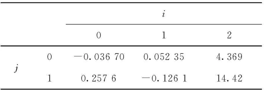
表2 Lee公式各系数取值
2015年,Hyun等[24]基于Lee等[21]的cohesive模型,检验了材料参数对裂纹尺寸的影响,并提出了通过材料屈服应变、泊松比、杨氏模量、压入载荷和裂纹长度识别材料断裂韧性的Hyun方法,其具体公式如下:
(6)
(7)
(8)
(9)
fi(v)=gijvj,i, j=0,1,2
(10)
其中:Hyun公式各系数取值如表3,公式(10)各系数取值如表4.

表3 Hyun公式各系数取值
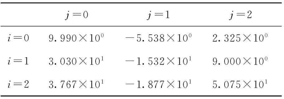
表4 公式(10)各系数取值
2 数值计算
为了分析比较3种典型基于数值分析的压痕法计算公式(Tang公式[17]、Lee公式[21]、Hyun公式[24])对陶瓷材料断裂韧性的测试精度,本文通过商用有限元Abaqus软件[29]建立陶瓷材料Vickers压入有限元模型.由于Vickers压头是面角为136°的正四棱锥,根据对称性结合裂纹开裂方向去Vickers压头的1/4建立模型,如图2,其被压材料取相应的1/4模型,整个被压材料尺寸为4 000 μm×4 000 μm×2 000 μm(如图3),压头最大压入深度hm=5 μm.

图2 1/4对称的Vickers压头
Fig.2 Schematic diagram of the Vickers indenter 1/4 symmetry

图3 1/4对称的Vickers压入有限元模型
Fig.3 Finite element model of the Vickers indentation 1/4 symmetry
定义压头为理想弹性压头,其弹性模量和泊松比分别为Ei=1 141 GPa,νi=0.07;定义被压材料与金刚石Vickers压头的平面应变弹性模量之比η=[E/(1-0.22)]/[1 141/(1-0.072)],被测陶瓷材料为均匀、各向同性的率无关固体,压入比功[30]取值为:We/Wt=0.3~0.7,弹性模量取值分别为E=70 GPa、200 GPa、400 GPa和600 GPa,相应地η=0.063 5、0.181 7、0.363 4和0.545 1,应变硬化指数n=0(陶瓷材料为低硬化水平),相应的屈服强度取值σy=1.4~40 GPa,ν=0.2.压头与被压材料间的摩擦系数取定值0.16[31].根据接触核心区网格精细,远场非核心区网格稀疏的原则,最终,RC和HPC裂纹开裂模型的压头均划分为12 000个C3D4单元,被压材料划分为12 000个C3D8R单元和4 500个C3D4单元,其网格划分如图4.收敛性分析表明,两模型网格分析误差均不超过0.5%.
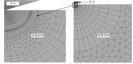
图4 有限元模型的网格划分
有关裂纹开裂面的建模,可通过被压材料沿压头对角线截面的对称性实现,即开裂面不作对称处理,未开裂面仍按对称设置.其具体裂纹面几何形状通过虚拟裂纹闭合法[25]计算得到接近真实情况的等KIC值半椭圆面作为裂纹开裂面.定义名义压痕对角线半长a为压头达到最大压入深度hm时对应的理论压痕对角线长度的一半.建立裂纹开裂半长c与名义压痕对角线半长a之比c/a=1.25、1.5、2.25、3、4.5和6的6种模型.其中,当c/a=1.25、1.5、2.25时,裂纹为RC开裂形式;当c/a=3、4.5、6时,裂纹为HPC开裂形式.
3 结果分析

对图5~7基于数值分析压痕法的3种数值公式理论误差进行分析可知,Tang公式和Lee公式所测断裂韧性值与理论计算值的最大误差均随比功增加而增大,其最大误差分别为193.39%和81.99%;Hyun公式除对弹性模量E=70 GPa、We/Wt=0.7的材料测试误差高达-75.59%之外,其余材料范围测试误差均处于30.65%之内(E=70 GPa、We/Wt=0.7的材料超出了Hyun公式的适用范围),较其他压痕法计算公式测试精度最高.
显然,采用叠加原理的Tang公式误差明显高于采用粘结单元的Lee公式和Hyun公式,其主要原因在于,叠加原理适用于线弹性材料,虽然陶瓷材料具有较高的屈服强度和较小的应变硬化指数,但是将具有弹塑性参数的陶瓷材料近似用线弹性方法进行叠加计算,从而得到的断裂韧性值必然存在一定偏差.而粘结单元仿真结果的准确性依赖于单元最大拉应力σmax、网格尺寸e、粘结过程区(Cohesive Process Zone)LCZ的有效设定,虽不适用于较短裂纹开裂形式(如RC裂纹开裂形式),但相比于叠加原理间接计算KIC的方法显然更为准确.此结论可进一步通过实验进行验证.
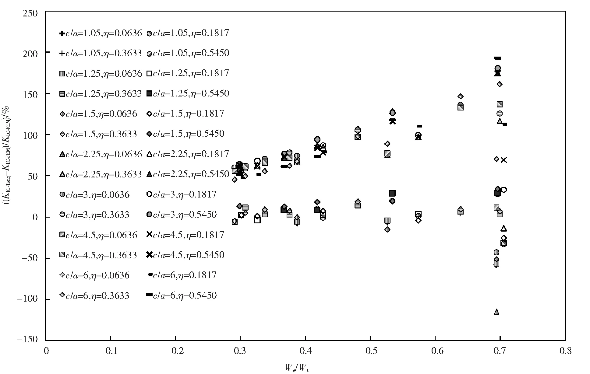
图5 c/a为1.25~6时不同η下的 (KIC-Tang-KIC-FEM)/KIC-FEM与We/Wt关系
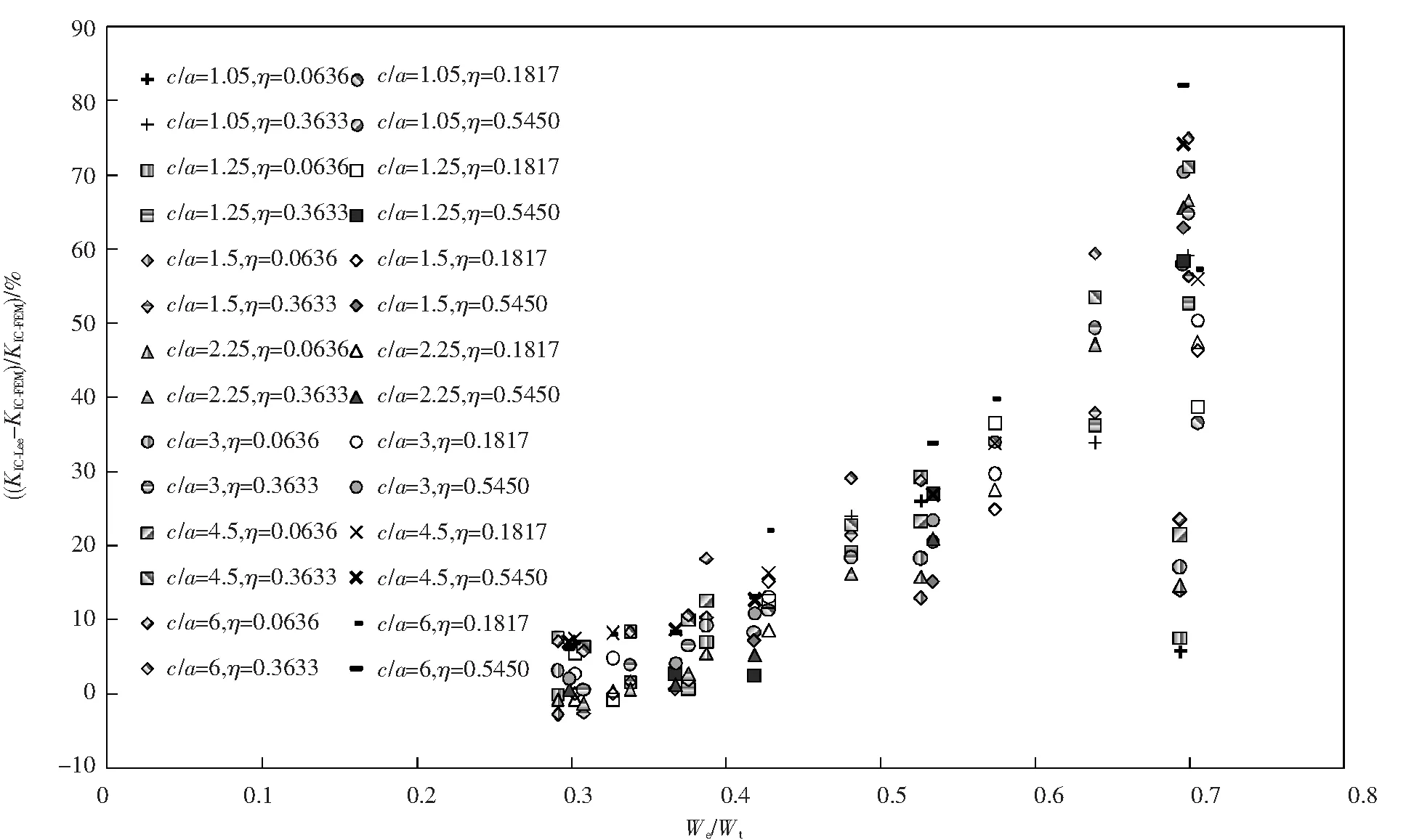
图6 c/a为1.25~6时不同η下的 (KIC-Lee-KIC-FEM)/KIC-FEM与We/Wt关系

图7 c/a为1.25~6时不同η下的 (KIC-Hyun-KIC-FEM)/KIC-FEM与We/Wt关系
4 实验验证
本文实验选用的被测陶瓷材料为按照国际标准ISO14577-1[33]要求制备的SRM2100和Fused Silica压入标准试样块.其中,SRM2100试样为美国National Institute of Standards & Technology 提供的陶瓷断裂韧性标准参考材料,其断裂韧性标准值为4.572±0.228 MPa·m1/2;Fused Silica试样为中国宝山钢铁股份有限公司提供的纳米压入仪用标准样品(GSB 03—2496-2008),其断裂韧性标准值为0.798±0.023 MPa·m1/2[34].应用先期获得国家发明专利授权的高精度宏/微观仪器化压入仪[35]和金刚石Vickers压头对上述2种陶瓷材料进行仪器化压入实验.考虑到不同压入载荷对被压材料压痕形貌的影响,对SRM2100试样选用最大压入载荷Pm=100 N进行弹性模量和断裂韧性测试,而对于Fused Silica试样,由于其在压入载荷较大时容易形成横向裂纹(Lateral Crack)[28,36]从而影响弹性模量的识别精度,故选用最大压入载荷分别为Pm=0.25 N和Pm=2 N进行弹性模量和断裂韧性测试.为保证测试结果的准确性,每种材料实验重复进行10次,取有效数据进行计算.图8和图9分别为SRM2100试样10次实验的Vickers压痕形貌图及载荷-位移曲线图.图10和图11分别为Fused Silica试样10次实验的Vickers压痕形貌图及载荷-位移曲线图.其中, Fused Silica试样在P=0.25 N时有1组实验数据由于载荷-位移曲线拟合指数较为奇异而舍去.
对已进行了仪器化Vickers压入测试的试样利用光学显微镜分别量取Vickers压痕实际对角线半长a′=(a1+a2)/2和Vickers压痕对角线方向上的裂纹开裂半长c=(c1+c2+c3+c4)/4,如图12,从而可以分别获得2种材料的仪器化压入有效测试结果,如表5~7所列.其中,材料弹性模量E由文献[30]所提方法获得,屈服强度σy由有限元数值方法通过图13中所示关系获得,Hn=Pm/A(hm)被定义为名义硬度,即最大压入载荷Pm与金刚石Vickers压头横截面积A(hm)之比.
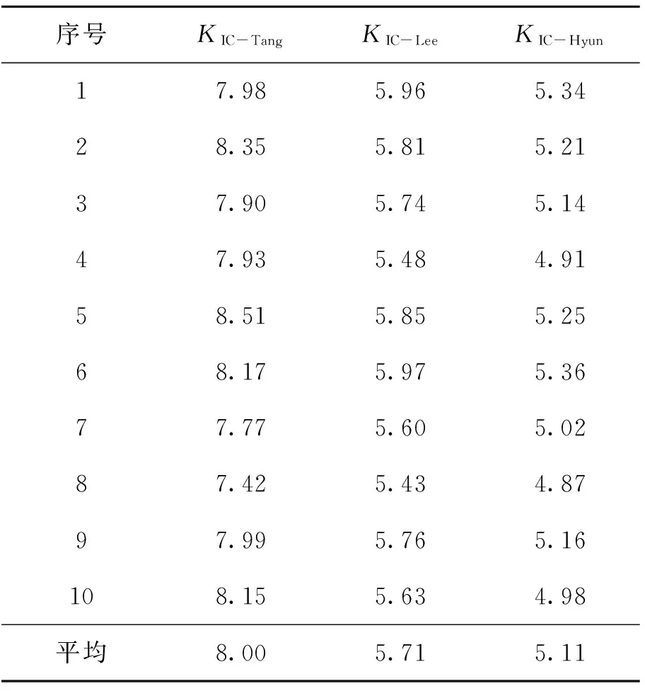
进一步根据Tang公式、Lee公式以及Hyun公式计算上述2种材料的断裂韧性值,结果见表8、表9.各种方法所测2种材料的断裂韧性值与其标准值的相对误差见表10,其中SRM2100试样的标准值KIC-S=4.572±0.228 MPa·m1/2,Fused Silica试样的标准值KIC-S=0.798±0.023 MPa·m1/2.
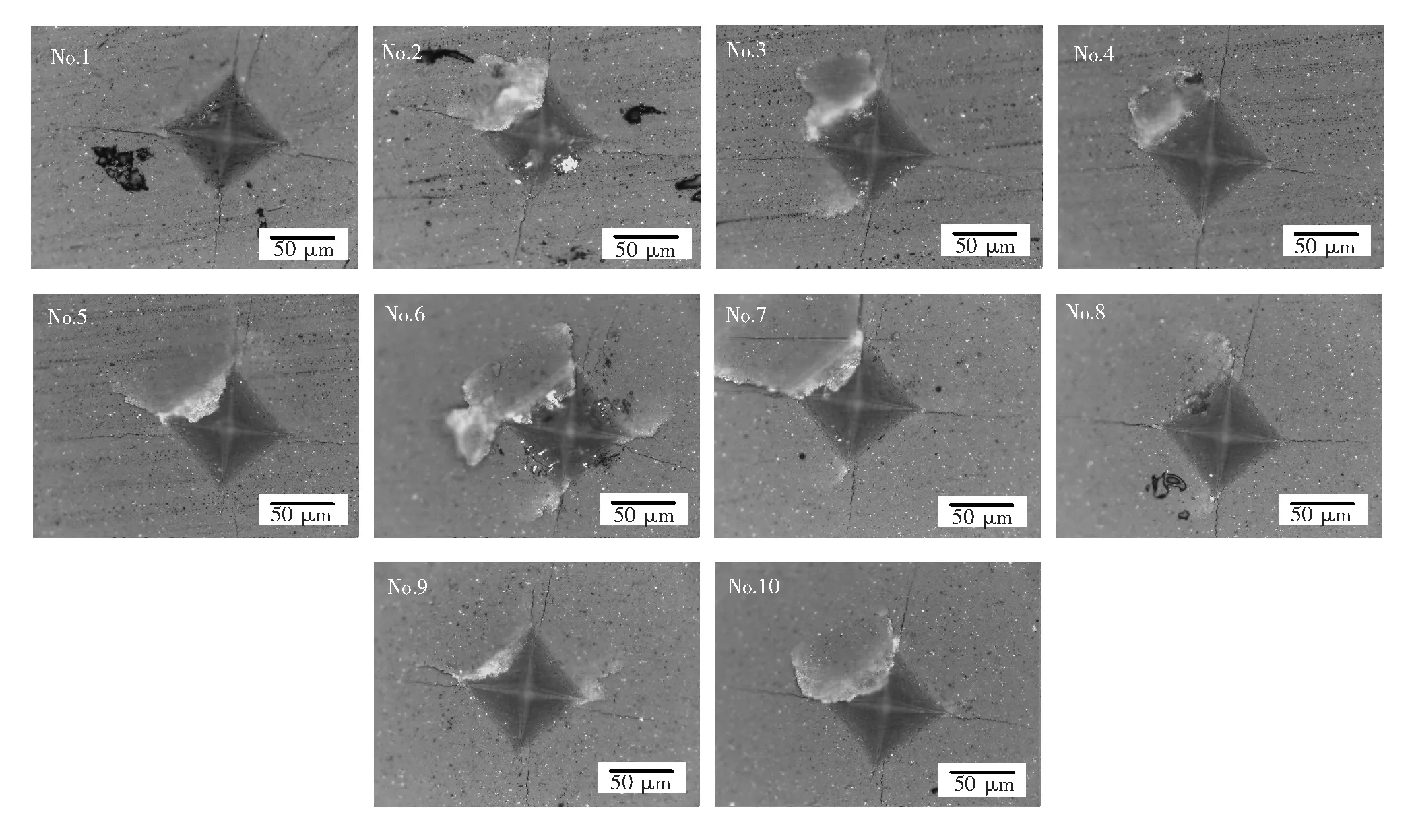
图8 SRM2100试样10次实验的Vickers压痕形貌
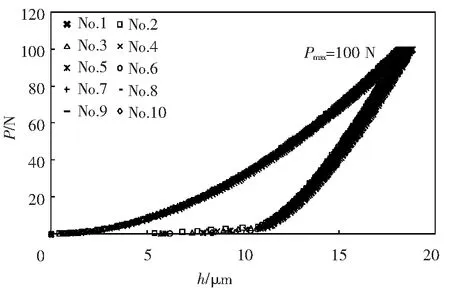
图9 SRM2100试样10次实验的载荷与位移曲线
由表10可以看出,SRM2100和Fused Silica 2种材料应用Tang公式获得的断裂韧性均值与其标准值的相对误差分别为74.97%和44.86%,Lee公式相对误差分别为24.89%和24.06%,Hyun公式相对误差分别为11.76%和21.05%,上述公式的实验测试结果相对误差与理论分析误差分布趋势一致且均符合其理论误差范围.
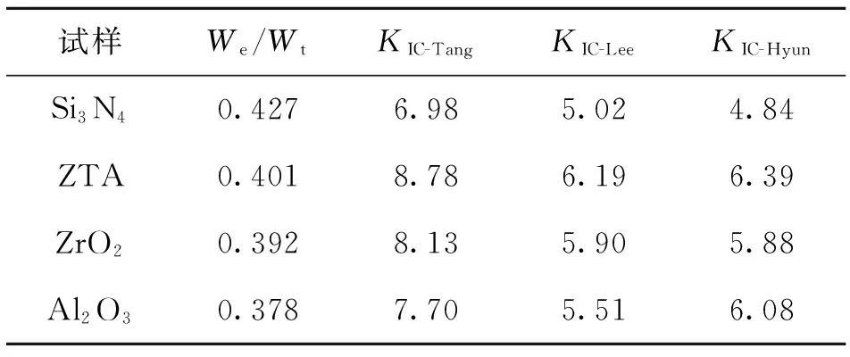
为了进一步验证上述3种压痕法测试误差结论,本文另外对中国建筑材料科学研究总院陶瓷科学研究院提供的4种典型陶瓷材料(Si3N4、ZTA、ZrO2、Al2O3)进行断裂韧性仪器化压入实验,其Vickers压痕形貌图如图14,测试结果见表11.其中,试样密度分别为3.21 g/cm3、6.02 g/cm3、4.28 g/cm3和3.95 g/cm3,采用高纯超细粉料(原料纯度≥99.9%)通过等静压成型方法制得.
由表11测试结果可以看出,3种压痕法所测4种陶瓷材料的断裂韧性值各不相同且差异较大,但各方法所得测试结果大小分别符合图5~7各方法理论误差范围;同时,不同压痕法对4种材料的测试结果符合各自理论误差随比功的分布趋势.以上实验结果充分说明,本文对3种基于数值分析压痕法测试陶瓷材料断裂韧性KIC值的精度分析是准确客观的,同时,Hyun公式相比其他压痕法计算公式测试精度较高.
5 结 论
本文采用虚拟裂纹闭合法的基本原理对基于数值分析的压痕法识别陶瓷材料断裂韧性精度问题进行研究,分析比较了3种典型基于数值分析的压痕法计算公式对陶瓷材料断裂韧性的测试精度和所测材料的适用范围,结论如下.
(1)Tang公式和Lee公式所测断裂韧性值与理论计算值的最大误差均随比功增加而增大,其最大误差分别为193.39%和81.99%;

图10 Fused Silica试样10次实验的Vickers压痕形貌

图11 Fused Silica试样10次实验的载荷与位移曲线

图12 Vickers压痕及裂纹开裂半长 图13 基于有限元数值方法计算的陶瓷材料σy/Hn与We/Wt关系
Fig.12 Schematic diagram of the Vickers impression based and crack half-length Fig.13 The relationship of ceramic materials betweenσy/HnandWe/Wton the finite element numerical method

表5 最大压入载荷为100 N时,SRM2100试样的仪器化压入测试结果
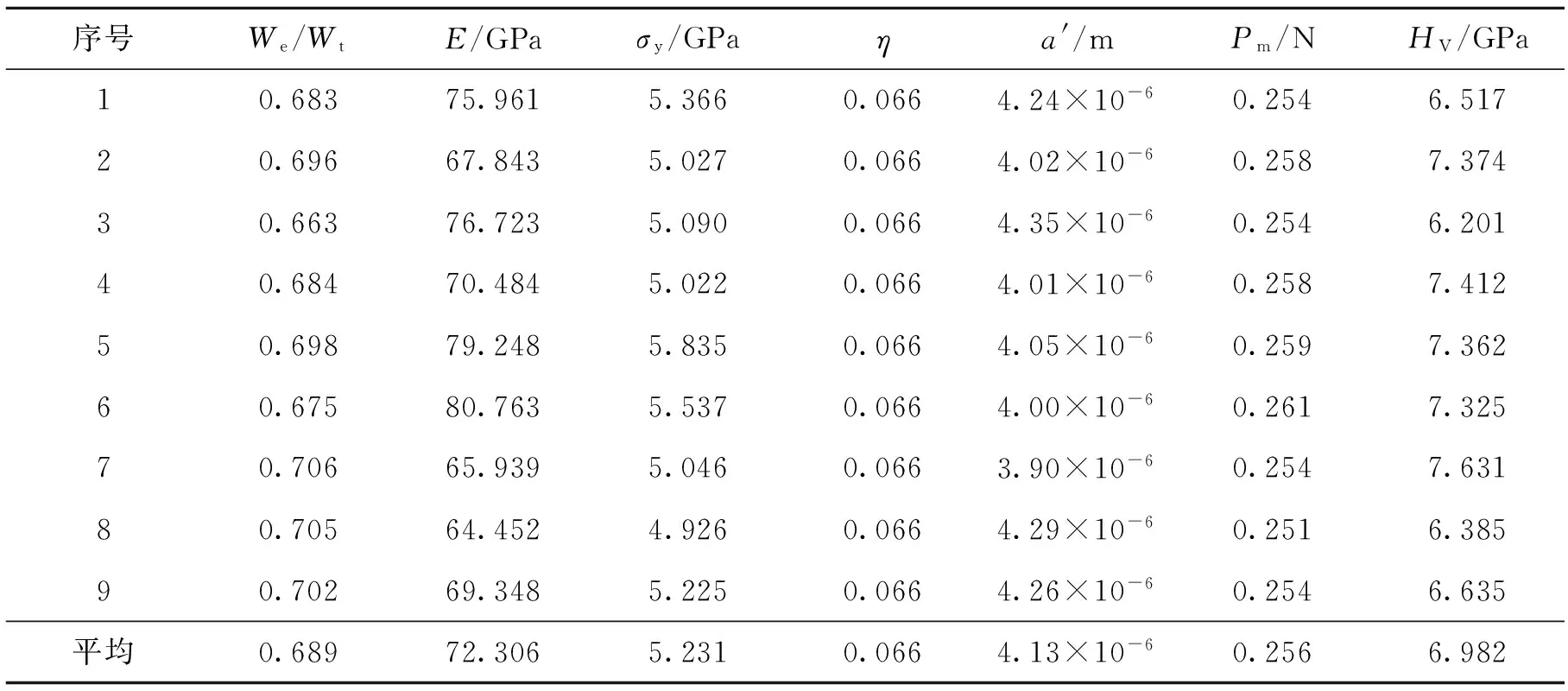
表6 最大压入载荷为0.25 N时,Fused Silica试样的仪器化压入测试结果

表7 最大压入载荷为2 N时,Fused Silica试样的仪器化压入测试结果
注:①We/Wt、E、σy为表6获得的实验数据;② 有2组实验数据由于裂纹开裂尺寸c/a过小而舍去.
表8 3种压痕法对SRM2100试样断裂韧性的测试结果
Tab.8 The measurement results of fracture toughness for SRM2100 with three indentation method
序号KIC-TangKIC-LeeKIC-Hyun17.985.965.3428.355.815.2137.905.745.1447.935.484.9158.515.855.2568.175.975.3677.775.605.0287.425.434.8797.995.765.16108.155.634.98平均8.005.715.11
表9 3种压痕法对Fused Silica试样断裂韧性的测试结果
Tab.9 The measurement results of fracture toughness for Fused Silica with three indentation method

序号KIC-TangKIC-LeeKIC-Hyun10.451.020.6620.441.000.6430.451.020.6540.461.050.6750.410.920.5960.420.950.6170.430.970.6280.420.950.61平均0.440.990.63
(2)Hyun公式除对弹性模量E=70 GPa、We/Wt=0.7的材料测试误差高达-75.59%之外,其余材料范围测试误差均处于30.65%之内;相比Tang公式和Lee公式,Hyun公式明显具有较高的测试精度.

图14 4种典型陶瓷材料在Pmax=100 N时的Vickers压痕形貌

表10 3种压痕法所测SRM2100和Fused Silica试样断裂韧性值与其标准值的相对误差
表11 3种基于数值分析压痕法对其他几种陶瓷材料断裂韧性的测试结果
Tab.11 The measurement results of fracture toughness for other ceramic materials with three indentation method
试样We/WtKIC-TangKIC-LeeKIC-HyunSi3N40.4276.985.024.84ZTA0.4018.786.196.39ZrO20.3928.135.905.88Al2O30.3787.705.516.08
(3)本文采用的虚拟裂纹闭合法计算陶瓷材料断裂韧性值简洁、有效,为下一步研究建立具有测试精度高、适用范围广的新型断裂韧性测试方法提供了一定的理论基础.
[1] American Society for Testing and Materials. ASTM-C1421 Standard Test Methods for Determination of Fracture Toughness of Advanced Ceramics at Ambient Temperature [S]. West Conshohocken: ASTM International,2010.
[2] International Organization for Standardization. ISO18756-2003 Fine ceramics (advanced ceramics, advanced technical ceramics)-Determination of fracture toughness of monolithic ceramics at room temperature by the surface crack in flexure (SCF)method [S].Switzerland: International Organization for Standardization,2003.
[3] International Organization for Standardization. ISO24370-2005 Fine ceramics (advanced ceramics, advanced technical ceramics)-Test method for fracture toughness of monolithic ceramics at room temperature by chevron-notched beam (CNB) method [S]. Switzerland: International Organization for Standardization,2005.
[4] Munz D, Bubsey R T, Shannon J L. Fracture toughness determination of AL2O3 using four-point-bend specimens with straight-through and chevron notches[J].Journal of American Ceramic Society,1979,63(5-6):300-305.
[5] International Organization for Standardization. ISO15732-2003 Fine ceramics (advanced ceramics, advanced technical ceramics)-Test method for fracture toughness of monolithic ceramics at room temperature by single edge precracked beam (SEPB) method[S]. Switzerland: International Organization for Standardization,2003.
[6] 全国工业陶瓷标准化技术委员会.GB/T 23806—2009精细陶瓷断裂韧性试验方法-单边预裂纹梁(SEPB)法[S].北京:中国标准出版社,2009.
[7] Ma J, Qi Q, Bayley J, et al. Development of SENB toughness measurement for thermoset resins[J].Polymer Testing, 2007, 26(2007):445-450.
[8] Damani R, Gstrein R, Danzer R. Critical Notch-Root radius effect in SENB-S fracture toughness testing[J]. Journal of European Ceramic Society, 1996,16(1996):695-702.
[9] Evans A G, Charles E A. Fracture toughness determination by indentation [J]. Journal of American Ceramic Society, 1976, 59(7-8): 371-376.
[10] Lawn B R, Evans A G, Marshall D B. Elastic/plastic indentation damage in ceramics: the median/radial crack system [J]. Journal of American Ceramic Society, 1980, 63(9-10): 574-581.
[11] Anstis G R, Chantikul P, Lawn B R, et al. A critical evaluation of indentation techniques for measuring fracture toughness: I, direct crack measurements [J]. Journal of American Ceramic Society, 1981,64(9): 533-538.
[12] Japanese Industrial Standard.JISR1607-1995. Testing Methods for Fracture Toughness of High Performance Ceramics [S].Tokyo:Japanese Standards Association, 1995.
[13] Niihara K, Morena R. Hasselman D P H. Evaluation of KIC of brittle solids by the indentation method with low crack-to-indent ratios [J]. Journal of Materials Science Letter, 1982,l(1): 13-16.
[14] Lankford J. Indentation microfracture in the Palmqvist crack regime: implications for fracture toughness evaluation by the indentation method [J]. Journal of Materials Science Letter, 1982, 1: 493-495.
[15] Laugier M T. New formula for indentation toughness in ceramics [J]. Journal of Materials Science Letter, 1987, 6: 355-356.
[16] Yan J, Karlsson A M, Chen X.On internal cone cracks induced by conical indentation in brittle materials[J]. Engineering Fracture Mechanics, 2007, 74(2007):2535-2546.
[17] Tang Y, Yonezu A, Ogasawara N, et al. On radial crack and half-penny crack induced by Vickers indentation[J]. Proceedings of the Royal Society A,2008,464(2008): 2967-2984.
[18] Amador A M, Silva I C, et al. An expression to determine the Vickers indentation fracture toughness obtained by the finite element method on Fe2B layers[J]. Surface & Coatings Technology, 2013,215(2013):285-290.
[19] Muchtar A, Lim L C, Lee K H. Finite element analysis of Vickers indentation cracking processes in brittle solids using elements exhibiting cohesive post-failure behavior[J].Journal of Materials Science,2003,38(2003):235-243.
[20] Guo X, Chang K, Chen L Q, et al. Determination of fracture toughness of AZ31 Mg alloy using the cohesive finite element method[J].Engineering Fracture Mechanics, 2012, 96(2012): 401-415.
[21] Lee J H, Gao Y F, Johanns K E, et al. Cohesive interface simulations of indentation cracking as a fracture toughness measurement method for brittle materials[J].Acta Materialia, 2012,60(2012):5448-5467.
[22] Johanns K E, Lee J H, Gao Y F, et al. An evaluation of the advantages and limitations in simulating indentation cracking with cohesive zone finite elements[J].Modelling and Simulation in Materials Science and Engineering, 2014,22(1):1-21.
[23] Hyun H C, Rickhey F, Lee J H, et al. Characteristics of indentation cracking using cohesive zone finite element techniques for pyramidal indenters[J].International Journal of Solids and Structures, 2014, 51(2014): 4327-4335.
[24] Hyun H C, Rickhey F, Lee J H, et al. Evaluation of indentation fracture toughness for brittle materials based on the cohesive zone finite element method[J],Engineering Fracture Mechanics,2015,134(2015):304-316.
[25] Rybicki E F, Kanninen M F.A finite element calculation of stress intensity factors by a modified crack closure integral [J]. Engineering Fracture Mechanics,1977,9:931-938.
[26] Palmqvist S. A method to determine the fracture toughness brittle materials, especially hard metals [J]. Jenkontorets Ann,1957,141:303-307.
[27] Yonezu A, Xu B, Chen X. Indentation induced lateral crack in ceramics with surface hardening[J].Materials Science and Engineering A,2009,507(2009):226-235.
[28] Wang Jialiang, Ma Dejun, Chen Wei, et al. Analysis of pop-in phenomenon in the process of ceramic materials instrumented indentation[J].Advanced Materials Research, 2014, 941-944(2014): 564-568.
[29] 庄卓,由小川,廖剑晖,等.基于ABAQUS的有限元分析和应用[M]. 北京:清华大学出版社,2009.
[30] 马德军.材料力学性能仪器化压入测试原理[M]. 北京:国防工业出版社, 2010.
[31] Antunes J M, Menezes L F, Fernandes J V. Three-dimensional numerical simulation of Vickers indentation tests [J]. International Journal of Solids and Structures, 2006,43(2006):784-806.
[32] Bouzakis K D, Michailidis N. Indenter surface area and hardness determination by means of a FEM-supported simulation of nanoindentation[J]. Thin Solid Films.2006,494:155-160.
[33] International Organization for Standardization. ISO14577-2002 Metallic materials-Instrumented indentation test for hardness and materials parameters Part 1: Test method[S]. Switzerland: International Organization for Standardization,2002.
[34] Wiederhorn S M. Fracture surface energy of glass [J]. Journal of American Ceramic Society.1969, 52:99-105.
[35] 马德军,宋仲康,郭俊宏,等.一种高精度压入仪及金刚石压头压入试样深度的计算方法[P].中国专利: CN102288500A. 2011-12-21.
[36] Oliver D J, Bradby J E, Williams J S, et al. Giant pop-ins and amorphization in germanium during indentation[J].Journal of Applied Physics,2007,101(4):1-9.
(责任编辑 苏晓东)
Study on Accuracy Problem of Indentation Method Based on the Numerical Analysis to Evaluating the Fracture Toughness of Ceramic Materials
WANG Jia-liang1, MA De-jun1, SUN Liang1, XIAO Fu-jun2
(1.Department of Mechanical Engineering, Academy of Armored Force Engineering, Beijing 100072, China;2. Nanjing Military Representative Bureau, General Armament Ministry, Nanjing 210024,China)
By using the virtual crack closure technique, the accuracy problem of indentation method, which is based on the numerical analysis to evaluating the fracture toughness of ceramic materials, is studied. The accuracy of three typical formulas established by numerical analysis are analyzed and compared. The results show that, for Tang and Lee formulas, the errors between measured and theoretical values increase withWe/Wtincreasing, and the maximum errors are 193.39% and 81.99%, respectively. The maximum errors of the Hyun formula are all within 30.65% except the material withE=70 GPa andWe/Wt=0.7( errors up to -75.59%). Compared with Tang and Lee formulas, Hyun formula has obviously higher test accuracy. This work provides a theoretical basis for reasonably using indentation method to obtain the values of ceramic materials' fracture toughness, and lays a foundation for establishing a new testing method with high accuracy and wide range of application.
numerical analysis; indentation method; ceramic materials; fracture toughness; the ratio of unloading work to total loading work
1004-8820(2015)04-0277-12
10.13951/j.cnki.37-1213/n.2015.04.009
2015-04-23
军队科研计划项目(2014CJ011).
王家梁(1986- ),男,陕西咸阳人,博士研究生,研究方向为材料力学性能测试技术.
TQ174.75
A

