
Safe operation of inverted siphon during ice period*
2015-04-20 05:52FUHui付辉YANGKailin杨开林GUOXinlei郭新蕾GUOYongxin郭永鑫WANGTao王涛
水动力学研究与进展 B辑 2015年2期
关键词:王涛
FU Hui (付辉), YANG Kai-lin (杨开林), GUO Xin-lei (郭新蕾), GUO Yong-xin (郭永鑫),WANG Tao (王涛)
State Key Laboratory of Simulation and Regulation of Water Cycle in River Basin, China Institute of Water Resources and Hydropower Research, Beijing 100038, China, E-mail: fuhui_iwhr@126.com
Introduction
The Beijing-Shijiazhuang section in the Middle Route of the South-to-North Water Diversion Project starts from Guyunhe and ends up at Tuancheng Lake,with an overall length of about 307 km. The 227.4 km long canal from Guyunhe to Beijumahe is an open channel. The other 80.1 km long canal from Beijumahe to Beijing is a pipeline, with 16 inverted siphons arranged along this section.
For open channel water diversion projects in the high latitude area in China, previous reports indicate that the inverted siphons might be jammed by ice,such as the inverted siphons of the Shahe irrigation district in 2003 and the water diversion project from Yellow River to Baiyangdian in 2008. For preventing the inverted siphons from ice jamming, the discharge of the Beijing-Shijiazhuang section in the Middle Route of the South-to-North Water Diversion Project was reduced to about 10 m3/s which was only 1/6 of the design discharge. For a long distance water diversion project, once one of inverted siphons is jammed,the safe operation of the whole project will be threatened. So the water diversion efficiency of the water diversion projects is significantly lower during the ice period[1-3].
At present, many studies focused on the ice cover and the bend channel[4-6]. But the studies for the safe operation of the inverted siphon during the ice period were few, and similar studies include the ice transportation through a submerged gate[7]. The ice accumulation processes at the inlet of an inverted siphon are modeled under a real ice condition on the experiment platform at the China Institute of Water Resources and Hydropower Research, and the hydraulic conditions for the ice jam prevention are analyzed. Experimental results provide some information for the safe operation of the inverted siphons at the Beijing-Shijiazhuang section.
1. Ice entrainment and transportation
In hydrostatics, the forces on the ice are balanced by gravity and buoyancy. But in hydrodynamics, the forces on the ice come also from the additionalBernoulli’s effect and the flow separation[8](as shown in Fig.1 and Fig.2).
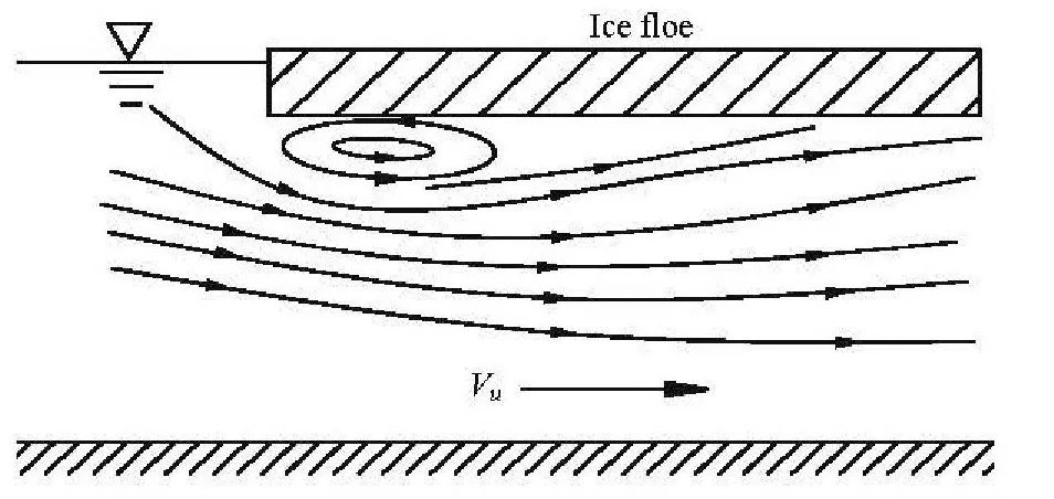
Fig.1 Schematic diagram of flow separation
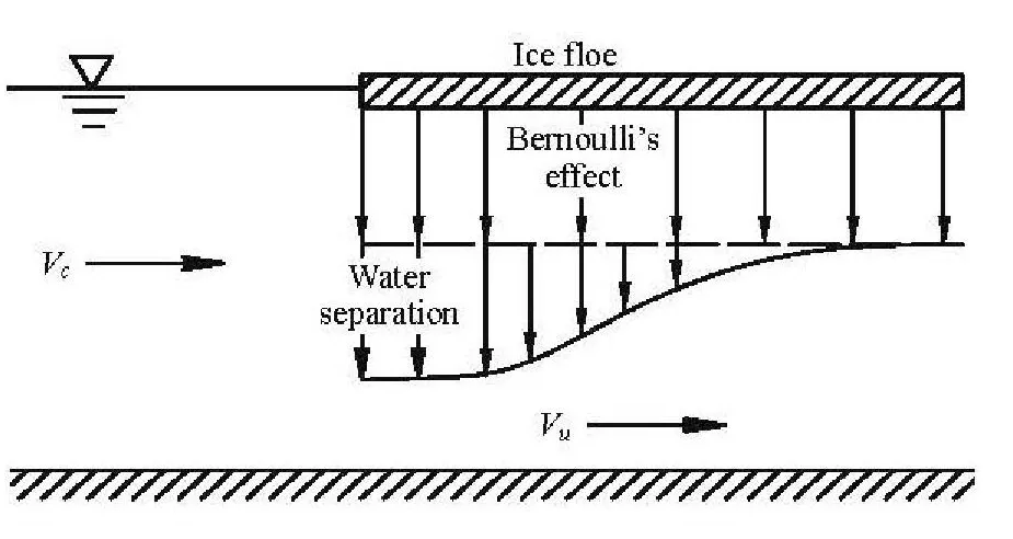
Fig.2 Negative pressure distribution caused by Bernoulli effect and flow separation
The critical condition of the ice entrainment can be described by[9]
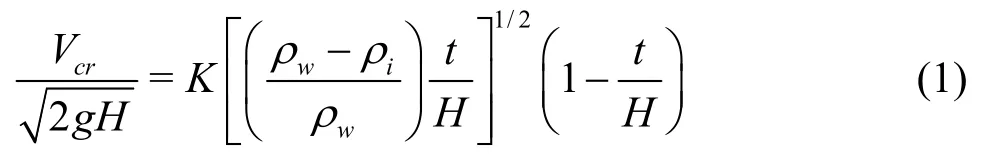
whereFrcris the critical Froude number,Vcris the critical velocity upstream of the ice,gis the acceleration of gravity,iρandwρrepresent the densities of the ice and the water, respectively,tis the thickness of the ice,His the total water depth,Kis a coefficient.
The critical condition of the under-turning submergence can be described as[9]
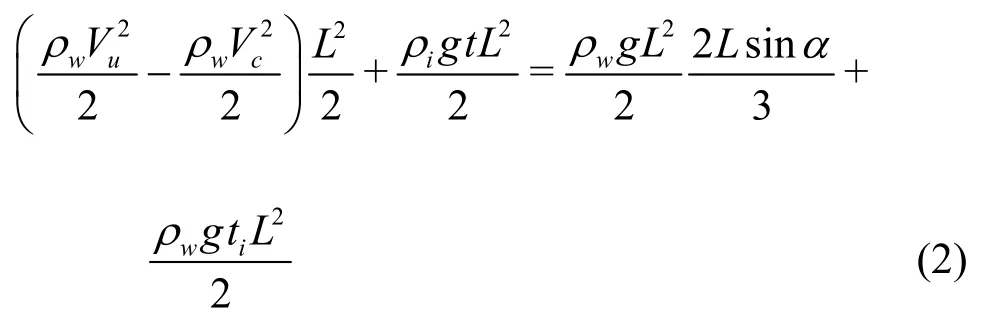
whereVcis the flow velocity of the upstream open channel,Vuis the flow velocity under the ice,Lis the length of the ice,αis the under-turning angle when the leading edge of the ice just submerges,tiis the ice thickness below the water surface.
The under-turning angleαcan be calculated as
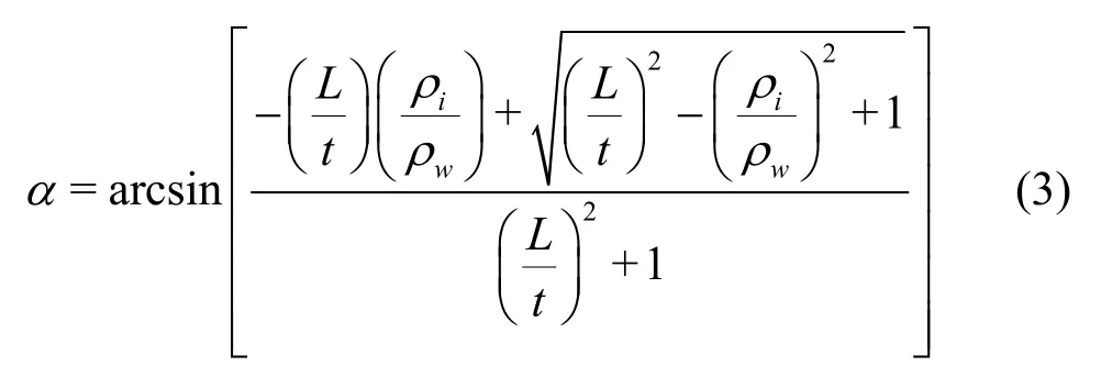
When the ice submerges at the leading edge of the ice jam, it may be transported downstream or accumulate at the bottom of the ice jam to thicken the ice jam. This critical hydraulic conditions can be described as[10]
wheresjis the porosity of the ice jam,si=ρi/ρw.
During the last 30 years, it was generally believed that the most important variables were the Froude number based on the outlet velocity and the depth of the top of the outlet beneath the upstream water surface and the ratio of the outlet depth to the full depth. A good discrimination between the entrainment and the non-entrainment was achieved using these variables[7].So the upstream Froude number of the inverted siphon is used to judge the safe operation conditions of the inverted siphon.
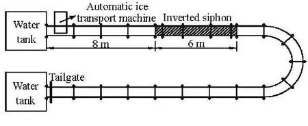
Fig.3 Layout of inverted siphon experiment
2. Experimental set up
A series of experiments are conducted in a flume of 50 m long, 0.8 m wide and 0.8 m high at the State Key Laboratory of the China Institute of Water Resources and Hydropower Research. An inverted siphon of 6 m long is used to model the typical Tanghe inverted siphon at the Beijing-Shijiazhuang section,and the model scale is 1:23.4 (according to the width of the flume and the prototype dimension of the Tanghe inverted siphon). Because of the limitation of the laboratory length, the horizontal length of the inverted siphon model is shortened. The ice of 0.0276 m×0.018.6 m×0.0025 m is used to model the ice accumulation and transportation at the inlet of theinverted siphon. Detailed arrangement of the inverted siphon and the flume is shown in Fig.3.
The real ice experiment platform is automatic,and includes a control computer, a DDC device drive and data collecting module, axial flow fans, centrifugal fans, a heating system, a temperature feed-back system, 9 refrigeration units. 27 high-accuracy temperature sensors which provide real-time temperature readings for the temperature control system are distributed in the platform. By this air temperature control system, the lowest temperature can be -15oC, with a control accuracy of ±0.5oC, and the temperature fluctuation less than 1oC. The detailed performance and the control mode of this platform were described by Fu et al.[11].
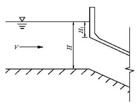
Fig.4 Schematic diagram of the inverted siphon inlet
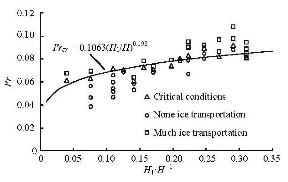
Fig.5 Ice entrainment of inverted siphon under different conditions
3. Critical Froude number for ice jam prevention of inverted siphon
The schematic diagram of the inverted siphon inlet is shown in Fig.4,H1is the submerged water depth from the water surface to the top of the inlet,andHis the total water depth. 49 real ice experiments are carried out, with the values ofH1/Hbetween 0.039 and 0.330. These cases cover the normal operation conditions of the inverted siphons at the Beijing-Shijiazhuang section. With the increase of the value ofH1/H, the critical Froude number for judging the ice transport also increases. At the low submerged depth,the critical Froude number is about 0.06, at the high submerged depth, the critical Froude number can reach 0.08-0.09. Obviously, the ratio between the submerged depth and the total water depth is a key factor for the ice jam prevention. Along with the increase of the submerged depth, a greater hydrodynamic force is needed to overcome the transportation resistance from the water surface to the inverted siphon.
Results of 49 experiments are shown in Fig.5.The critical condition for the ice to be transported into the inverted siphon can be described as
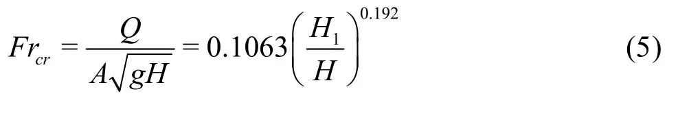
whereQis the flow discharge of the canal,Ais the cross-sectional area of the canal.
The curve described by Eq.(5) shows a critical condition for the safe operation of the inverted siphon during the ice period. The hydraulic conditions below the curve are safe, which gives the safe condition for the operation of the water diversion project during the ice period. The hydraulic conditions above the curve will be unsafe and may lead to ice jamming.
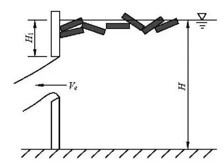
Fig.6 Ice entrainment at submerged gate
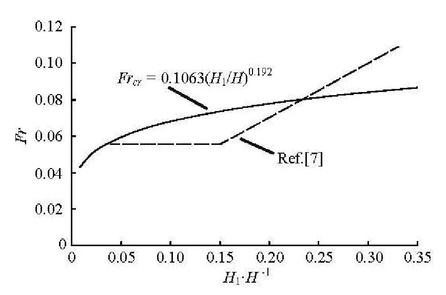
Fig.7 The difference between experimental results and those in Ref.[7]
Equation (5) is valid forH1/Hin the range between 0.039 and 0.330. The wind, the water level fluctuation and other factors might easily promote the ice transportation. For the ice jam prevention in practicalengineering, it is better for the submerged depth to be controlled as high as possible by the gate during the ice period, especially, under the low submerged depth conditions. So under a practical operation condition, it is better for for the Froude number to be controlled below the curve as shown in Fig.5. WhenH1/H>0.33, the critical Froude number should be controlled between 0.08 and 0.09, which seems to be near the flow condition of the ice entrainment at the leading edge of the ice cover[12-14]. For a long distance water diversion project, the safe operation is the prior consideration, so a Froude number less than 0.09 is suggested even under high submerged depth conditions.
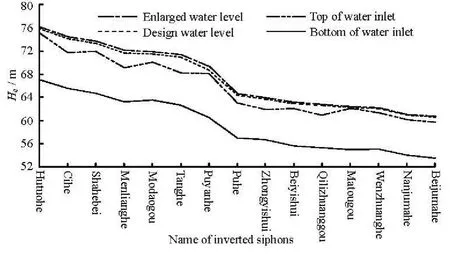
Fig.8 Design parameters of inverted siphons
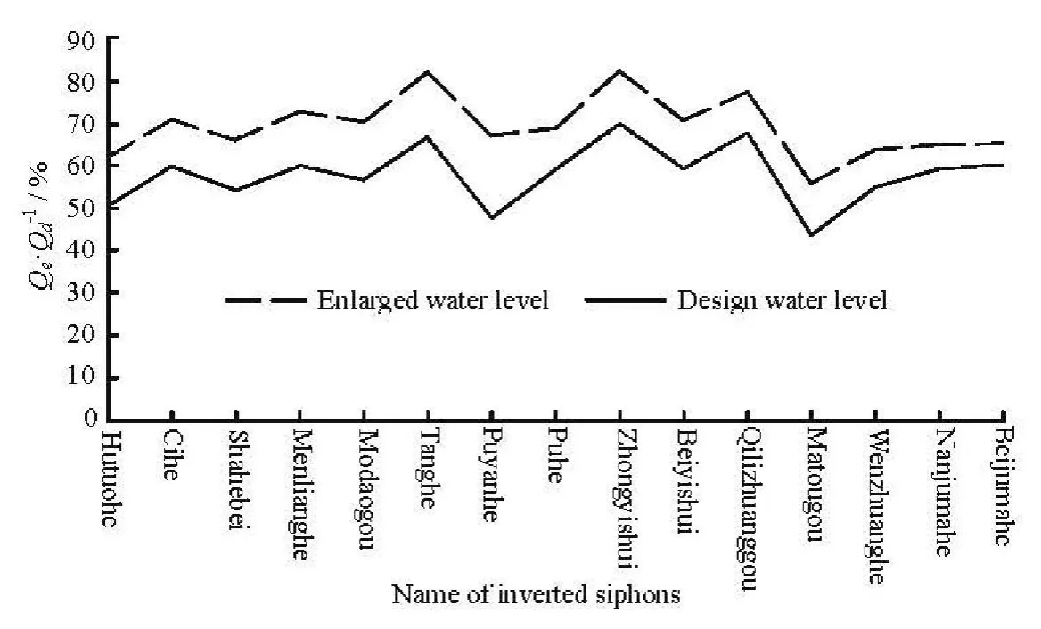
Fig.9 Ratio between water diversion capacity (at design and maximum water level) and design discharge
Equation (5) is different from that for the submerged gate of Ref.[7], which suggested that when,can be used to judge the ice entrainment(Fig.6). The main reason for this difference might be the viscous effect.Plastic was used in Ashton’s experiments, while in the inverted siphon experiment, the real ice is used. When the flow dynamic force is small (a low Froude number), the ice adheres to each other, grows in size and then the stability of the ice increases. So under a low Froude number condition, the critical Froude number of the ice entrainment of the real ice is greater than that of the plastic ice (Fig.7). Along with the increase of the flow dynamic force (a high Froude number), the viscous effect is reduced (as compared to the flow dynamic force). And the adhered ice breaks up into pieces of single or small size ice. For the real and plastic ices of the same size, the critical entrainment velocity of the plastic ice is greater than that of the real ice by about 40%-50%. So under the high Froude number condition (Fr> 0.07), the critical Froude number of the ice entrainment of the real ice is smaller than that of the plastic ice (Fig.7). The different shapes of the submerged gate and the inverted siphon might be another reason[15,16].
4. Safe operation of inverted siphon
From Hutuohe to Beijumahe, the top and bottom elevations of the inlet, the design and maximum water levels of 15 inverted siphons at the Beijing-Shijiazhuang section are shown in Fig.8 (the design parameters of the Jiehe inverted siphon are not available). And the vertical coordinate represents elevationHe.
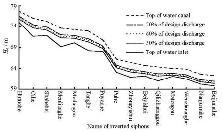
Fig.10 Minimum operation water level of 50%, 60% and 70% of design discharge along the section
By the water diversion along the canal of the Beijing-Shijiazhuang section, the design discharge decreases from 170 m3/s to 60 m3/s and the maximum discharge decreases from 200 m3/s to 70 m3/s. Because of different dimensions, and different design and maximum water levels shown in Fig.8, the submerged depth of every inverted siphon shows irregular variations.
Equation (5) is used to analyze the maximum safe operation discharge of 15 inverted siphons at the design and maximum water levels. Because of the insufficient submerged depth, all inverted siphons at the Beijing-Shijiazhuang section cannot safely transfer the design discharge at the design or maximum water levels during the ice period.
From Fig.9, it is obvious that the water diversion capacity (Qs) of the Beijing-Shijiazhuang section is limited by the Hutuohe, Puyanghe and Matougou inverted siphons, and the water diversion capacity is about 50.2%, 47.7% and 43.6% of the design discharge (Qd) at the design water level, respectively. If the operation water level is increased from the design water level to the maximum water level, the water diversion capacity of these three inverted siphons can be increased to reach 62.2%, 66.9% and 55.7% of the design discharge, respectively. Under this condition, the water diversion capacity of the canal is limited by the Matougou inverted siphon.
The water diversion capacity of a canal is decided by the structure of the lowest water diversion capacity. So it means that if the operation water level of the Beijing-Shijiazhuang section is adjusted to the design and maximum water levels, the maximum water diversion capacity of the whole section is 43.6% and 55.7% of the design discharge, respectively, because of the limitation of the Matougou inverted siphon.
For the Middle Route of the South-to-North Water Diversion Project, the 1.5 m safety freeboard is reserved in the design. So if a part of this safety freeboard can be used to improve the water diversion capacity of some limitation structures as the Matougou inverted siphon, the water diversion efficiency of the whole canal can be improved.
For the Beijing-Shijiazhuang section, if the water diversion objective is controlled as 50% of the design discharge, the minimum operation water level of the inverted siphons is in the range of from 0.11 m to 1.09 m below the maximum water level and the safety freeboard is not to be used. If the water diversion objection is controlled as 60% of the design discharge,only 0.09 m safety freeboard of the Matougou inverted siphon needs to be used, the operation water level of other inverted siphons is in the range of from 0.09 m to 0.71 m below the maximum water level. If the water diversion objection is controlled as 70% of the design discharge, the safety freeboard from 0.03 m to 0.29 m of 9 inverted siphons (Hutuohe, Shahebei,Puyanghe, Puhe, Qilizhuang, Matougou, Wenzhuanghe, Nanjuma and Beijuma) need to be used. Among them, Hutuohe and Matougou inverted siphons need 0.26 m and 0.29 m, respectively. The minimum operation water levels of the inverted siphons are shown in Fig.10 and the operation discharges are 50%, 60% and 70% of the design discharge, respectively.
Based on above analyses, it is a safe option that the operation discharge is controlled as 50% of the design discharge, all inverted siphons can operate below the maximum water level. When the water diversion capacity is controlled as 60% of the design discharge,the Matougou inverted siphon needs 0.09 m safety freeboard, and the water capacity of the canal can increase 10%. This operation regulation takes into account both the safety and the efficiency. If the water diversion capacity is controlled as 70% of the design discharge, the safety freeboard of most inverted siphons needs to be used, and the operation is unsafe during the ice period[17,18].
It is necessary to point out that the above mentio-ned control water level is the minimum value for the operation, and the exact value needs to be confirmed by prototype tests.
5. Conclusions
(1) A series refrigerated experiments are conducted in an ice laboratory, to study the hydraulic conditions of the ice jam prevention for inverted siphons at the Beijing-Shijiazhuang section of the Middle Route of the South-to-North Water Diversion Project during the ice period.
(2) Based on the critical cases for the ice to be transported into the inverted siphon, the relationship betweenH1/Hand the critical Froude number of the upstream canalFrcris obtained and this relationship is used to analyze the water diversion capacity and the operation water level of inverted siphons at the Beijing-Shijiazhuang section.
(3) The advantages and the disadvantages of three operation methods for 50%, 60% and 70% of the design discharge are studied during the ice period. The related operation water level is shown in Fig.10. For 15 inverted siphons, the operation discharge with 50%of the design discharge is a safe selection, with 60%of the design discharge both the safety and the efficiency are taken into account, with 70% of the design discharge, the operation discharge seems to be an unsafe selection. It is best for the discharge of these inverted siphons to be controlled as 60% of the design discharge. These analysis results provide references for the ice jam prevention of inverted siphons during the ice period.
[1] FU Hui, YANG Kai-lin and WANG Tao et al. Progress in the study of river ice hydraulics[J]. South-to-North Water Transfers and Water Science and Technology,2010, 8(1):14-18(in Chinese).
[2] WANG Jun, CHEN Pang-pang and SUI Jueyi. Progress in studies on ice accumulation in river bends[J]. Journal of Hydrodynamics, 2011, 23(6): 737-744.
[3] YANG Kai-lin. Theory of hydraulic control for modern water diversion projects[J]. South-to-North Water Diversion and Water Science and Technology, 2011,9(4): 1-7(in Chinese).
[4] WANG Jun, HE Liang and CHEN Pang-pang et al. Numerical simulation of mechanical breakup of river icecover[J]. Journal of Hydrodynamics, 2013, 35(3):415-421.
[5] WANG Jun, LI Qing-gang and SUI Jueyi. Floating rate of frazil ice particles in flowing water in bend channels-A three-dimensional numerical analysis[J]. Journal of Hydrodynamics, 2010, 22(1): 19-28.
[6] BELTAOS S. Progress in the study and management of river ice jams[J]. Cold Regions Science and Technology, 2008, 51(1): 2-19.
[7] ASHTON G. D. Ice entrainment through submerged gate[C]. Proceedings of the 19th IAHR International Symposium on Ice. Vancouver, Canada, 2008, 129-138.
[8] DOW K. E., HICKS F. E. and STEFFLER P. M.. Experimental investigation of the pressure distribution beneath a floating ice block[J]. Journal of Hydraulic Engineering, ASCE, 2011, 137(4): 399-411.
[9] ASHTON G. D. Froude criterion for ice block stability[J]. Journal of Glaciology, 1974, 13(68): 307-313.
[10] LAL A. W., SHEN H. T. Mathematical model for river ice processes[J]. Journal of Hydraulic Engineering,ASCE, 1991, 117(7); 851-867.
[11] FU Hui, YANG Kai-lin and TAN Shui-wei et al. Development and application of low temperature ice-hydrodynamics experiment platform[J]. Journal of Hydraulic Engineering, 2013, 44(3): 355-360(in Chinese).
[12] SHEN H. T. Mathematical modeling of river ice processes[J]. Cold Regions Science and Technology, 2010,62(1): 3-13.
[13] MCFARLANE V., LOEWEN M. and HICKS F. Laboratory measurements of the rise velocity of frazil ice particles[J]. Cold Regions Science and Technology,2014, 106-107: 120-130.
[14] SUI J., KARNEY B. and SUN Z. C. et al. Field investigation of frazil jam evolution–A case study[J]. Journal of Hydraulic Engineering, ASCE, 2002,128(8): 781-787.
[15] LI Z. J., WANG Y. and LI G. On the flexural strength of DUT-1 synthetic model ice[J]. Cold Regions Science and Technology, 2002, 35(2): 67-72.
[16] SUI J., WANG J. and HE Y. et al. Velocity profiles and incipient motion of frazil particles under ice cover[J].International Journal of Sediment Research, 2010,25(1): 39-51.
[17] YANG Kai-lin, WANG Tao and GUO Xin-lei et al.Safety regulations of water conveyance in the Middle Route of South-to-North Water Diversion Project in ice period[J]. South-to-North Water Transfers and Water Science and Technology, 2011, 9(2): 1-8(in Chinese).
[18] FU H., YANG K. and GUO X. et al. Ice processes simulation for Middle Route of South-to-North Water Diversion Project[C]. Proceedings of 35th IAHR World Congress. Chengdu, China, 2013.
猜你喜欢
Chinese Physics B(2023年1期)2023-02-20
理科爱好者(教育教学版)(2022年2期)2022-05-05
三悦文摘·教育学刊(2022年7期)2022-04-27
Plasma Science and Technology(2022年2期)2022-03-10
大众文艺(2020年23期)2021-01-04
大众文艺(2020年22期)2020-12-13
艺术家(2018年12期)2018-03-18
- 水动力学研究与进展 B辑的其它文章
- A general framework for verification and validation of large eddy simulations*
- Direct calculation method of roll damping based on three-dimensional CFD approach*
- Visualization study on fluid distribution and end effects in core flow experiments with low-field mri method*
- Large-eddy simulation of the flow past both finite and infinite circular cylinders at Re =3900*
- Flow field simulation of supercritical carbon dioxide jet: Comparison and sensitivity analysis*
- Ship hull optimization based on wave resistance using wavelet method*