Compensation for observed coupling effect in measuring angular deformation of ship hull by laser gyroscope units
YANG Yun-tao, WANG Xing-shu, HUANG Zong-sheng, WU Wei
(College of Opto-electronic Science and Engineering, National University of Defense Technology, Changsha 410073, China)
Compensation for observed coupling effect in measuring angular deformation of ship hull by laser gyroscope units
YANG Yun-tao, WANG Xing-shu, HUANG Zong-sheng, WU Wei
(College of Opto-electronic Science and Engineering, National University of Defense Technology, Changsha 410073, China)
Angular deformation of ship hull is a main alignment error source in transfer alignment and must be accurately calibrated by measurement equipment. By using two laser gyroscope units (LGUs), the angular deformation of ship hull is calculated by attitude matching method. But the observation coupling effect induced by the cross correlation of dynamic deformation and angular rate of ship motion leads to inaccuracy results of optimal estimation. The observation coupling effect cannot be measured by the attitude matching method, and must be measured by other instruments. According to angular rate matching method, the observed coupling effect is studied, and a bias error which causing angular deformation is obtained. It is shown that the bias error can be modulated by angular rate of ship motion. By compensating the angular rate measured by LGUs, the coupling effect is reduced, and high-accuracy alignment results can be achieved. Simulations validates that it is the coupling effect that leads to inaccuracy evaluation of static deformation.
angular deformation measurement; attitude matching; observation coupling effect; static deformation; laser gyroscope unit
Angular deformation measurement[1]of ship hull structure are commonly applied to scientific instrumentation vehicles[2]and other naval warships[3-4]. On these large sized vehicles, there are fitted with some peripheral apparatus such as radar antennas, optic systems, etc. Angular orientation of coordinate frame of the subsystems located in different positions and at a distance from the central Master Inertial Navigation System (MINS) can be misaligned with the MINS due to manufacturing tolerance and installation inaccuracies. If there are no flexible body deformations, the alignment errors are referred to as static deformation. In addition, the structure of ship being not completely rigid will flex and deform in response to force of sea waves and also due to solar heating, giving rise to deformation changing with time. So the dynamic deformation and quasi-static deformation are defined as two components of angular deformation. The measurement of angular deformation become urgent and necessary in order to maintain a unified attitude reference of all locations or equipment onboard the entire ship[5]. This is essential when transfer alignment[6-7]is to be carried out for a weapon system on a military vehicle or even to prevent possible damage or destruction on a transport ship due to the changing cargo situation.
In the paper [8], only based on ring laser gyroscope unit (LGU), an angular rate matching method is derived and represents the relationship of two groups of measuring angular rates respectively when the deformation angles are assumed to be small. The dynamic deformation of ship structure is approximated as second order Gauss-Markov process, thus a linear Kalman filter[9]can be used to estimate angular deformations. Considering that quasi-static deformation is changing slowly with time, it is seen as irregular and nonstationary process and only represented as random walk process with unit root in z-transformation[10]. Moreover, the paper [11] derived another attitude matching method with higher signal to noise ratio (SNR) than that of angular rate matching method.
But unfortunately, although improvements of angular deformation models and inertial measurement matching methods are much more, the accuracy of optimal estimation is barely satisfied. The reference [12] analyzed an observed coupling effect, which denotes cross correlation of dynamic deformation and angular rate of ship motion by means of structural dynamics.
In this paper, we derived the error function of angular rate matching method. By analyzing the expectation of error function, we can get the reason of observed coupling effect. In Section 1, angular rate matching and attitude matching methods based on body coordinate frame are re-described and a Kalman filter for estimating angular deformation is applied. Section 2 gives detailed explanation of observed coupling effect emergence. In Section 3, a compensation method for observed coupling effect is derived. Then some simulations are done and some conclusions are finally given in Section 4.
1 Inertial measurement matching methods
1.1 Angular rate matching method
Ship borne angular deformation measurement based on LGU directly measures angular rate, so angular rate matching method can be derived according to projection theorem. According to differential equation of rotating vector quaternion, angular rate matching method can be derived as below:


Seen from (1), the equation (2) is an approximation formula when assumingis small according to projection theorem.
Appling small angle approximations in (1), angular rate matching method is given by

In equation (3), there are two variable vectors and, in whichcan be seen as intermediate variable and determined by modellingthrough linear Kalman filter.
1.2 Attitude matching method on body coordinate frame
Attitude matching method based on local geographical coordinate system needs initial alignment provided by MINS, but in fact, the goal of attitude matching method for angular deformation measurement is transfer alignment, which also needs precise angular deformation. So it is obviously contradictory. Described by use of directional cosine matrix (DCM), attitude transition from master coordinate to slave coordinate is derived by[10]:

By applying small angle approximations, differential equation of (4) is represented as

Where Z and A are DCMs defined by the reference[11].
Comparing equation (5) with (3), initial attitude erroris considered. While considering gyro's measurement error, equation (5) becomes[10]:


1.3 Linear Kalman filter structure
Based on attitude matching method described by (6), an optimal filter can be built. By the reference [10], angular deformation are modelled and studied.
Angular deformations comprises of static deformation and dynamic deformation, so they can be modelled respectively as random process with unit root in z-transformation and second order Gauss-Markov random process as below[13-14].

Moreover, gyro's measurement error consists of two components, which are bias error and random walk error. The first component approximates a constant value and second component approximates white noise.

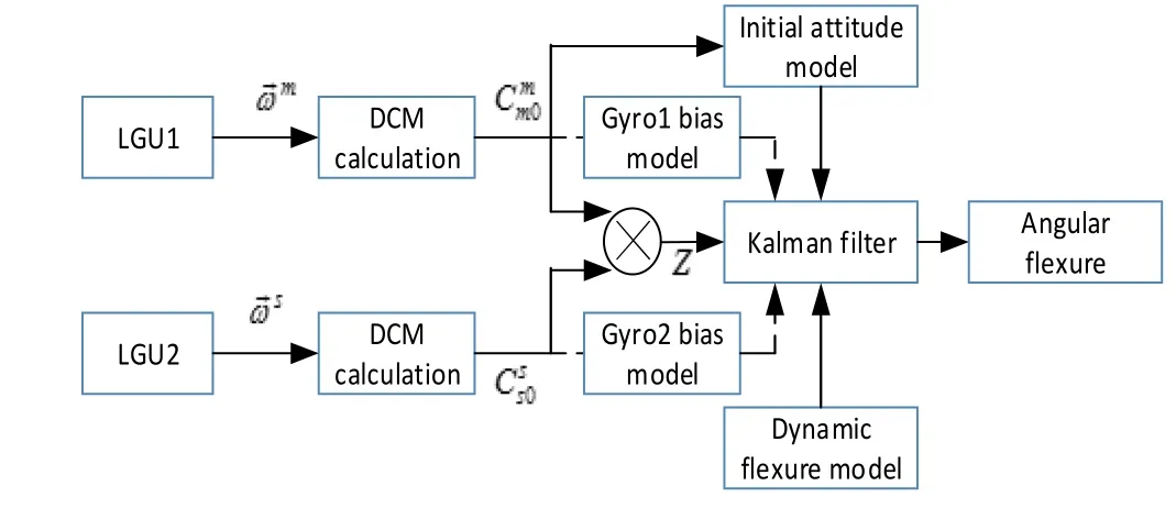
Fig. 1 Structures of Kalman filtering using attitude matching method for estimating angular deformations
According to equations (7)~(10), a linear Kalman filter is built, in which state vectors are presented as below:

By applying optimal estimation of Kalman filter, Fig.1 shows that angular deformation can be consecutively evaluated.
2 Observed coupling effect
The results of Kalman filtering for estimating angular deformation is optimal, and good models are very important. According to angular rate method (3), the error function is given by


Because Kalman filter is an optimal filter in least square criterion, the residual error of observation Z in eq. (6) approximates statistically Gaussian probability distribution with expectation of zeros. The expectation of (13) is

When equation (14) is statistically right, observed coupling effect will be emerged. In other words, angular rate of ship motion and dynamic deformation are cross correlated statistically.
Derive error inequality of (12) as (15):

Inequality (15) is representation of piece wise stationary random process approximation. Where cond(.) denotes condition number and equation solvability. From (15) some inferences are obtained.


And measurement function is given by (19).

A Kalman filter for estimating coupling angle vector is set up as Fig.2.
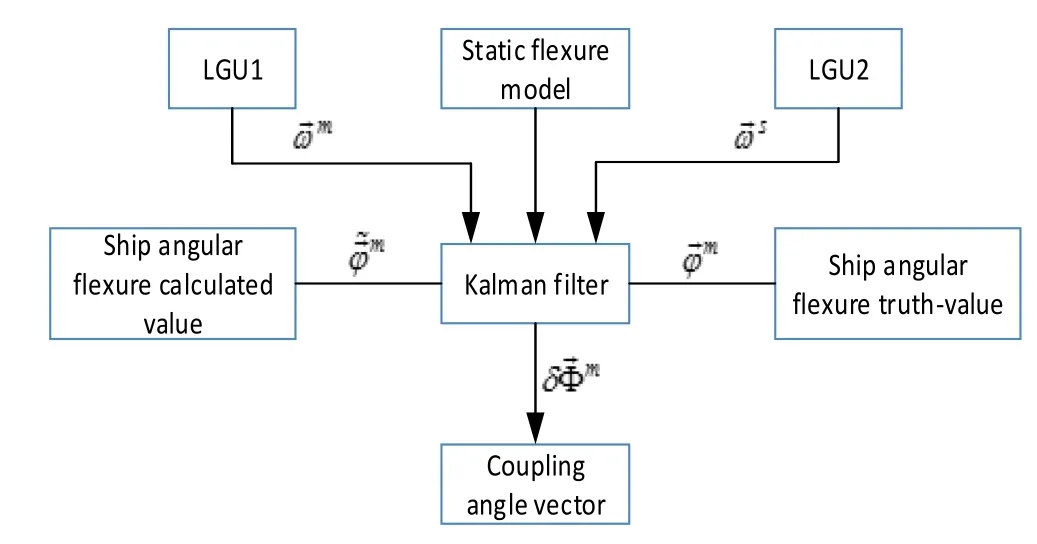
Fig.2 Schematic diagram of Kalman filtering for estimating error angular deformation
3 Compensation for observed coupling effect


4 Simulation experiments
Two simulations are done. The first simulation is estimating error angular deformation by Kalman filtering based on attitude matching method. Before and after compensating observed coupling effect, alignment errors are compared in the second simulation.
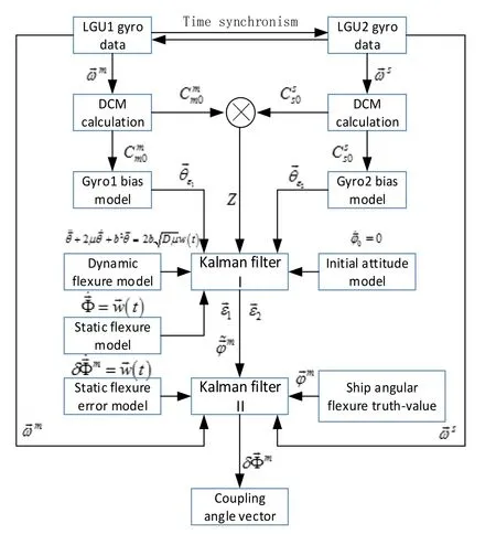
Fig.3 Schematic diagram of estimating error angular deformation for validating observed coupling effect
4.1 Simulation System Setup
Angular rate of ship motions induced by force of sea waves is approximated as a simplified second order Gauss-Markov process, and can be generated through an AR (auto regressive) filter with colored noise driven.
The auto correlation function of second order Gauss-Markov process of ship angular motions is represented as:

Where ξ denotes x, y or z axis,αξand βξare the variance, damping factor, and circular frequency respectively.

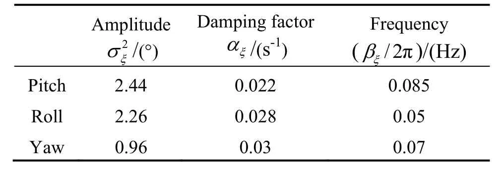
Tab.1 Parameters of AR (2) models of ship attitude
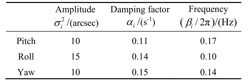
Tab.2 Parameters of AR (2) models of ship borne angular deformation
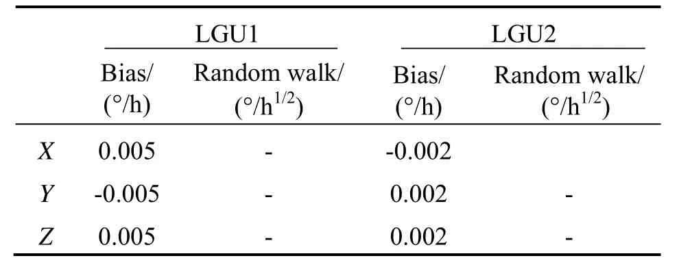
Tab.3 Parameters of gyroscopes’ noises
For validating the emergence of observed coupling effect, we must assume ship-borne attitude motions and angular deformations have same colored noise driven through AR (2) models. Considering that angular rate of ship motions and angular deformations are possibly cross correlated, we defined three groups of observed coupling effect conditions as below.


After that, we applied compensation algorithm (21) to observed angular rate of ship motions, then compared alignment errors with each other.
In addition, the static deformation is constant without consideration of slow varying quasi-static deformations.
4.2 Results and Analysis
The simulation results of three groups of observed coupling effect are shown in Fig.4. The first column diagrams showed that estimated alignment errors of attitude matching method through a linear Kalman filter, and in the second column diagrams coupling angles are evaluated by another Kalman filtering as described as Fig.3. The last column diagrams are estimated alignment errors of Kalman filtering after compensation for observed coupling effect.
The (I-1), (II-1) and (III-1) diagrams in Fig.4 validated that observed coupling effect caused bias error of static deformation, and different cross correlations have fewer bias error in pitch and roll axis coordinates, but have larger bias error in yaw axis coordinate. This indirectly verified that ship angular motions modulate amplitude of coupling angles. The (I-2), (II-2) and (III-2) diagrams in Fig.4 showed that if we can acquire accurate dynamic deformation, coupling angles induced by observed coupling effect are determined precisely as Fig.3. After compensating angular rate of ship motions for estimated coupling angles above, alignment errors are much smaller than before compensation as shown as the (I-3), (II-3) and (III-3) diagrams in Fig.4.
5 Conclusion
A linear Kalman filter for evaluating coupling angle based on angular rate matching method is proposed. According to acquire accurate dynamic deformation, coupling angles are determined. Simulation results validated that cross correlation of angular rate of ship motions and angular deformations can result in estimated bias error of static deformation through a Kalman filter based on attitude matching method, especially alignment error of yawing is much larger because of modulation of ship angular motions. According to estimated coupling angles, we can compensate angular rate of ship motions and thus get more accurate alignment results of Kalman filtering based on attitude matching method.
Observed coupling effect in attitude matching method cannot be measured by LGU, thus we don’t acquire more accurate alignment results with bias error. Compensation for observed coupling effect is essential and indispensible.
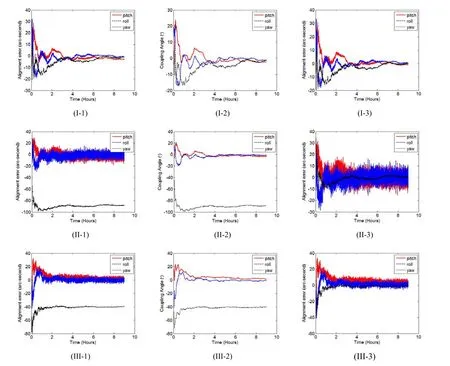
Fig.4 Comparison of alignment errors among three groups of observed coupling effect conditions
[1] Hutcheson L D. Ship flexure measurement[R]. CA: Naval Weapon Center, Report AD A06349, Aug., 1975.
[2] Wang G, Pran K, Sagvolden G, Havsgard G B, et al. Ship hull structure monitoring using fibre optic sensors[J]. Smart Materials and Structures, 2001, 10(3): 472-478.
[3] Shoals P G, Brunner D E. Dynamic ship flexure measurement program[R]. Report A047040, Naval Ship Weapon Systems Engineering Station Port Hueneme, CA, 1973.
[4] Kain J E, Cloutier J R. Rapid transfer alignment for tactical weapon applications[C]//Proc. AIAA Conf. Guidance, Navigation and Control. Boston, USA, 1989: 1290-1300.
[5] Day D L, Arrud J. Impact of structural flexure on precision tracking[J]. Naval Engineers J., 1999, 111(3): 133-138.
[6] Sun F, Guo C J, Gao W, Li B. A new inertial measurement method of ship dynamic deformation[C]//Conf. Mechatronics and Automation. Harbin, China, 2007: 3407-3412.
[7] Joon L, Lim Y C. Transfer alignment considering measurement time delay and ship body flexure[J]. J. Mechanical Science and Technology, 2009, 23(1): 195-203.
[8] Mochalov A V, Kazantsev A V. Use of ring laser units for measurement of the moving object deformation[C]// Proceeding of the SPIE. 2002, Vol.4680: 85-92.
[9] Schnider A M. Kalman filter formulations for transfer alignment of strapdown inertial units[J]. Navigation, 1983, 30(1): 72-89.
[10] ZhENG Jia-xing, QIN Shi-qiao, WANG Xing-shu. Ship hull angular deformation measurement taking slowvarying quasi-static component into account[J]. Journal of Chinese Inertial Technology, 2011(1): 6-10.
[11] ZHENG Jia-xing, QIN Shi-qiao, WANG Xing-shu, HUANG Zong-sheng. Attitude matching method for ship deformation measurement[J]. Journal of Chinese Inertial Technology, 2010, 18(2): 175-180.
[12] WU Wei, QIN Shi-qiao, CHEN Sheng. Coupling influence of ship dynamic flexure on high accuracy transfer alignment[J]. Int. J. Modelling, Identification, and Control, 2013, 19 (7): 224-234.
[13] WU Wei, ChEN Sheng, QIN Shi-qiao. Online estimation of ship dynamic flexure model parameters for transfer alignment[J]. IEEE Transactions on Control Systems Technology, 2013, 21(5): 1666-1678.
[14] WU Wei, QIN Shi-qiao, CHEN Sheng. Determination of dynamic flexure model parameters for ship angular deformation measurement[C]//Proc. UKACC Control 2012. Cardiff, UK, 2012: 964-969.
1005-6734(2014)05-0561-06
10.13695/j.cnki.12-1222/o3.2014.05.001
激光陀螺组合体测量船体角形变中观测耦合效应的补偿
杨云涛,王省书,黄宗升,吴 伟
(国防科学技术大学 光电科学与工程学院,长沙 410073)
船体角形变是传递对准中的主要误差源,需要依靠测量仪器精确标定。根据姿态匹配方法使用两套激光陀螺组合体可以计算角形变。但是动态形变和船体运动角速度的交叉相关的观测耦合效应导致角形变的最优估计结果不准确,并且通过姿态匹配方法这种观测耦合效应是不能被准确测量的,需要结合其它角形变的测量信息进行计算。基于角速度匹配方法,研究了观测耦合效应,并得出其导致角形变估计的偏置误差,且受船体运动角速度调制的结论。通过补偿激光陀螺组合体测量的角速度,降低了观测耦合效应,得到了高精度的对准结果。仿真结果表明观测耦合效应主要导致了静态形变估计精度的不准确。
角形变测量;姿态匹配;观测耦合效应;静态形变;激光陀螺组合体;
U666.1
A
2014-04-20;
2014-08-14
国家自然科学基金项目(11172323)
杨云涛(1984—),男,博士研究生,从事光电仪器与测控技术研究。E-mail:legend08fda@126.com
联 系 人:王省书(1963—),女,教授,博士生导师。E-mail:gfkdwxs@163.com

