
Study on Relationship between Microstructure of Active Phase and HDS Performance of Sulfided Ni-Mo Catalysts: Effect of Metal Loading
2014-07-25 10:07GuoRongShenBenxianFangXiangchenSunJinPengChongCuiXiaoli
中国炼油与石油化工 2014年2期
Guo Rong; Shen Benxian; Fang Xiangchen; Sun Jin; Peng Chong; Cui Xiaoli
(1. State Key Laboratory of Chemical Engineering, East China University of Science and Technology, Shanghai 200237; 2. Fushun Research Institute of Petroleum and Petrochemicals, SINOPEC, Fushun 113001)
Study on Relationship between Microstructure of Active Phase and HDS Performance of Sulfided Ni-Mo Catalysts: Effect of Metal Loading
Guo Rong1,2; Shen Benxian1; Fang Xiangchen1,2; Sun Jin2; Peng Chong1,2; Cui Xiaoli2
(1. State Key Laboratory of Chemical Engineering, East China University of Science and Technology, Shanghai 200237; 2. Fushun Research Institute of Petroleum and Petrochemicals, SINOPEC, Fushun 113001)
Six Ni-Mo catalysts with different metal contents were prepared and characterized by N2adsorption and X-ray diffractometry. The active phase microstructure of these catalysts was examined by the Raman spectroscopy, temperatureprogrammed reduction (TPR), X-ray photoelectron spectroscopy, and high-resolution transmission electron microscopy. Hydrodesulfurization (HDS) activity of catalyst samples were analyzed in a flow fixed-bed microreactor. The sulfidation degree of Mo and the length of the MoS2slab slightly increased with the amount of metal loaded following sulfidation. This small change is attributed to polymolybdate species observed in all the oxidized catalysts. Weak metal-support interactions, as determined by the TPR technique, increased the NiSxsulfidation phase and MoS2slab stacking. The HDS activity of the catalyst samples increased with the number of active sites. For high metal loading catalysts, their HDS activity was nearly identical because the sulfur atoms cannot easily approach active sites. This change is caused by the large number of stacked layers in the MoS2slabs as well as the decrease in the specific surface area and pore volume of the catalyst samples with an increasing metal loading.
Ni–Mo catalysts, hydrodesulfurization, sulfidation, microstructure, metal loading
1 Introduction
To meet stringent environmental regulations, the sulfur content in diesel fuel must be reduced[1]. The sulfur content in liquid fuels in the United States was limited from 50 μg/g to 15 μg/g as specified by the ultra-low-sulfur diesel regulations in 2006[2]. In Europe and Japan, the accepted level of sulfur in diesel fuel products was reduced to 10 μg/g in 2008[3-4]. Other countries are expected to implement similar regulations in the future. Hence the hydrotreatment of liquid fuel, an important technique for producing ultra-low-sulfur diesel fuel, has gained considerable research interest[5–8].
The activity of catalysts, which is a key factor in hydrotreatment of liquid fuel, must be improved to develop economical and effective ways for producing clean diesel fuel[9]. Chianelli, et al.[10]initially developed an “edge-rim”model, in which two types of sites are distinguished by their location on the layers. The “edge” sites are associated with outer edges of the interior layers that can only cleave C—S bonds, whereas the “rim” sites are located at the top and bottom layers that can hydrogenate and cleave C—S bonds. Topsoe, et al.[11]reported that Ni-Mo-S or Co-Mo-S bond structures are responsible for the catalytic activity of Ni- or Co-promoted MoS2catalysts. Studies on the atomic structure of catalysts have identified two types of structures by scanning tunneling microscopy[12]. The structure possessing high intrinsic activity is de fined as type II, and that possessing low intrinsic activity is defined as type I[13]. In a type I structure, the interaction between the support and the active metal is strong, and the existent Mo-O-Al linkages cannot be sul fided completely[14]. By comparison, the type II structures may be sul fidized completely, while the Ni-Mo-S or Co-Mo-S bonds formed on multiple slab layers are not linked with the support.
The activity of catalysts can be improved by: selecting new supports, such as Al2O3-SiO2, Al2O3-TiO2, or mesoporous materials; using additives, such as B, F, or P; de-veloping impregnation methods using chelating agents, such as nitrilotriacetic acid and citric acid; adjusting the ratio of active metal to promoters; or varying the metal loading. Several works have confirmed the relevant theories mentioned above[15–20], and the activity of hydrotreating catalysts has been improved to produce clean diesel fuel. This study aims to determine the relationship between the active phase microstructure and hydrotreatment performance of Ni-Mo catalysts. The Ni-Mo hydrotreatment catalysts with different metal contents were prepared via the impregnation method, and the molar ratio of Ni/(Ni+Mo) was fixed at 0.3 to improve the catalytic performance[21]. The properties of the catalysts were characterized by N2adsorption technique and powder X-ray diffractiometry (XRD). The Raman spectroscopy, temperature-programmed reduction (TPR), X-ray photoelectron spectroscopy (XPS), and high-resolution transmission electron microscopy (HRTEM) were used to analyze the nature of the active phase microstructures of the catalyst samples. The performance of the catalysts was evaluated via the hydrodesulfurization of atmospheric straight-run diesel in a continuous flow fixed-bed microreactor.
2 Experimental
2.1 Preparation of catalysts
Commercial alumina support (provided by the Sinopec Catalyst Company Fushun Division) was selected as the catalyst carrier. Ni-Mo catalysts were prepared by impregnation with an aqueous solution of nickel nitrate [Ni(NO3)2·6H2O] and ammonium heptamolybdate [(NH4)6Mo7O24·4H2O]. The resultant catalysts were then dried at 110 ℃ and calcined at 500 ℃ for 3 h. Six different metal-loaded catalysts were prepared and they were named as CMo3Ni, CMo6Ni, CMo10Ni, CMo15Ni, CMo20Ni, and CMo25Ni. Table 1 presents the metal content of each catalyst.

Table 1 Properties of the support and oxidized catalysts
2.2 Characterization of catalysts
N2adsorption measurements were performed on a Micromeritics ASAP 2420 physical adsorption instrument at -196 ℃. Each sample was heated to 300 ℃ under vacuum for 3 h prior to testing. The XRD patterns of the samples were recorded on a Rigaku Miniflex powder diffractometer with CuKα radiation (λ=0.154 05 nm). The instrument was operated at 40 kV and 80 mA.
Dispersion of the molybdate oxide phase was observed by the Raman spectroscopy at room temperature on a Raman microprobe (HR800, Jobin Yvon S.A.S) equipped with a photodiode array detector. A Nd:YAG laser (532 nm) was used as the laser source.
The TPR tests were performed on a Micromeritics AutoChem 2920 instrument to analyze the reducibility of Ni and Mo metal oxides on the fresh catalysts. All catalyst samples were calcined at 450 ℃ for 1 h prior to analyses. The samples were heated from room temperature to 1 000 ℃ at a heating rate of 10 ℃/min under a 10% H2/Ar mixed gas flowing at a rate of 100 mL/min. The XPS experiments were performed by a Multilab2000X instrument (ThermoFisher Company) using Mg-Kαradiation; the instrument was operated at 1 253.6 eV. All spectra were corrected using 284.6 eV as the reference for C1s BE. The surface atomic ratios were calculated from the integrated peak intensity and atomic sensitivity factors using the XPS processing software by applying the Shirley background correction and Gaussian-Lorentzian decomposition parameters. The HRTEM measurements were performed on a JEM-2100 instrument operating at 200 kV.
2.3 Sulfidation and evaluation of the catalysts
Sulfidation and activity tests were carried out in a continuous flow fixed-bed microreactor. The sulfidation test was carried out as follows: About 10 mL of each catalyst was placed inside the reactor. The reactor was pressurized with H2at 4 MPa and heated to 110 ℃ at a temperature increase rate of 2 ℃/min. Sulfidizing oil (96% kerosene + 4% CS2) was then introduced into the reactor. After wetting the catalyst sample with the sulfidizing oil for 3 h, the reactor was heated to 360 ℃ at a temperature increase rate of 2 ℃/min and maintained at this tem-perature for 8 h. The straight-run diesel containing 1.7% of sulfur was selected as the feedstock which was introduced at a flow rate of 20 mL/h. Hydrogen gas was also introduced at a flow rate of 100 mL/min. The sulfur content of product was evaluated using an ANTEK-9000 sulfur content analyzer with Ar and O2serving as the carrier and burning gases, respectively. The burning temperature was 1 100 ℃.
3 Results and Discussion
3.1 Characterization of the oxidized catalysts
Six catalysts with different metal contents were synthesized to determine the relationship between the microstructure of active phase and hydrodesulfurization performance of Ni-Mo catalysts. Table 1 lists the properties of the support and the oxidized catalysts. The BET surface area and pore volume of the samples decreased successively for samples covering CMo3Ni to CMo25Ni with an increasing Mo and Co loading; this result may be ascribed to the thorough dispersion of the metal oxide on the support.

Figure 1 XRD patterns of six oxidized catalysts with different metal loadings
Figure 1 shows the XRD patterns of the catalyst samples. The patterns revealed two diffraction peaks at 2θof 46.0° and 66.7°, both of which corresponded to γ-Al2O3(JCPDF#29-0063). No metal oxide diffraction peaks were detected in any of the patterns, which indicated that metal oxides were well dispersed on the support. The BET surface area and pore volume of the catalyst CMo25Ni decreased significantly, although the XRD pattern of this catalyst was similar to those of the five other catalysts. This result was caused by the reason that no metal oxide crystallites were formed or the metal oxide crystallites were too small to be detected by XRD.
The Raman spectra are used to determine the state of oxomolybdate species in the support. Payen, et al.[22]identified three types of oxomolybdate species that were developed with an increasing amount of Mo loaded on the support. Monomolybdate species were generated at low Mo loading (usually below 0.6 Mo atoms per nm2) and characterized by a main line ranging from 920 cm-1to 930 cm-1. Characteristic lines at 952, 860, 560, 360, and 220 cm-1corresponded to polymolybdate species. MoO3microcrystallites were generated at higher Mo loadings and characterized by a main line in the range from 820 cm-1to 996 cm-1[23-24].
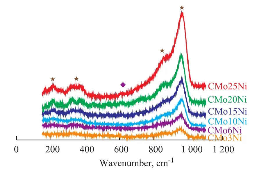
Figure 2 Raman spectra of six oxidized catalysts with different metal loadings
Figure 2 illustrates the Raman spectra of the catalyst samples. The Raman spectrum of the NiMoO4phase in the Ni-Mo/Al2O3catalysts can hardly be defined because the characteristic lines are very weak and overlapped with the broad characteristic lines of the polymolybdate species at low Ni content[23–25]. Ni species occupy the tetrahedral and octahedral sites in the NiAl2O4monolayer generated on Al2O3support surfaces. When a surface coverage of NiAl2O4monolayer is attained, the Raman characteristic lines at 620 cm-1[23-25]are detected on the Raman spectra of the sample CMo25Ni.
The characteristic Raman lines at 960, 862, 360, and 213 cm-1corresponded to CMo10Ni, CMo15Ni, CMo-20Ni, and CMo25Ni, respectively, whereas those at 960 cm-1corresponded to CMo3Ni and CMo6Ni. These lines confirmed the presence of the polymolybdate species in the catalyst samples. The lack of characteristic Raman lines of MoO3microcrystallites implied that the polymolybdate species were well dispersed on the support surface and agreed well with the XRD and BET results. This observation also confirmed that no metal oxide crystal-lites were generated in the catalyst samples.
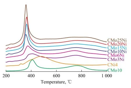
Figure 3 TPR profiles of six oxidized catalysts with different metal loadings in comparison with the reference oxidized catalysts (Mo-only and Ni-only)
Figure 3 shows the TPR profiles of six oxidized catalysts with different metal loadings. For comparative analysis, the mono-metal catalysts CMo10 (containing Mo only) and CNi4 (containing Ni only) were also tested. The CMo10 profile exhibited two reduction peaks at 410 ℃and 767 ℃. The former was attributed to the reduction of Mo6+to Mo4+whereas the latter was attributed to the reduction of Mo4+to Mo[26-27]. A reduction peak at 485 ℃was identified in the CNi4 catalyst, which corresponded to the reduction of NiO species at a temperature higher than that of bulk NiO (220 ℃)[28-29]. This result implies the strong interaction between NiO and the support.
The TPR profiles of the oxidized catalysts with different metal loadings showed remarkable changes compared with those of CMo10 and CNi4. Reduction peaks were observed from 360 ℃ to 395 ℃, which were lower than those observed in the unpromoted Mo catalyst; this finding indicated the weak interaction between the metal and the support in the presence of Ni, which was beneficial to sulfidation of active metals and formation of the type II Ni-Mo-S structures. The reduction temperature of CMo3Ni, CMo6Ni, and CMo10Ni decreased with an increasing amount of Mo, indicating to the weakening metal-support interaction. As more metal was loaded onto the support, the reduction temperature still decreased, and became nearly constant.
3.2 Characterization of the sulfidized catalysts
XPS was employed to determine the state of Mo and Ni after sulfidation. The spectrum of Mo3d was fitted by several constraints: (1) the theoretical spin-orbit splitting of the Mo3d peak was set at 3.15 eV; (2) the ratio of the peak area between Mo3d5/2and Mo3d3/2was kept constant at 1.5; and (3) the full width at half maximum height of the Mo3d5/2and Mo3d3/2peaks was assumed to be identical. The respective parameters in the case of Ni2p were: (1) 17.2eV, (2) 2eV, and (3) identical in value[30-31]. Figure 4 shows the results on decomposition of a typical CMo25Ni sample.

Figure 4 Decomposition of XPS Mo 3d (A) and Ni 2p (B) spectra of sample CMo25Ni
Three peaks representing different states of Mo3d can be observed in Figure 4(A). The doublets located at 228.7—228.9 eV and 231.8—232.0 eV corresponded to MoS2(Mo4+). Doublets at 232.5—232.7 eV and 235.6—235.8 eV corresponded to MoOX(Mo6+). An intermediate state of Mo oxysul fide (Mo5+) was observed on peaks at 231 eV and 234.1 eV[32–34]. Moreover, the peak at 226±0.1 eV corresponded to S2-2s[30,35]. In Figure 4(B), the doublet peaks at 852.7—852.9 eV and 869.9—870.1 eV corresponded to the sulfided nickel phase (NiSx), while those at 855.1—855.4 eV and 872.3—872.6 eV were attributed to NiO. The broad peaks observed at 860.9±0.1 eV were the satellite peaks of Ni2+[30-31,34]. The contrast on sulfidation degree of the six catalysts is summarized in Table 2.
Table 2 shows that the Mo4+/Mo atomic ratio increasedwith an increasing Mo content but these changes were not significant. This result was attributed to the polymolybdate species that were present in all of the catalysts, similar to findings in the Raman tests. With regard to the sulfidation degree of Ni phase, the ratio of NiSxincreased from 29.55% to 44.16% with an increasing metal content, because most Ni phases formed Ni-Al oxides with γ-Al2O3supports at low metal loadings, and Ni-Al oxides were difficult to be sulfidized. The TPR results revealed that the reduction peaks shifted to lower temperatures with an increasing metal loading. This finding confirmed that the nickel molybdate phase was easier to be reduced and sulfidized at higher metal loadings. The more the amount of nickel phases sulfidized and rearranged on the edges of MoS2slabs[36], the greater the extent of formation of the type II Ni-Mo-S structure would be.

Table 2 XPS results of all catalysts
The TEM images of six sulfidized catalysts revealed the morphologies and structures of MoS2slabs (Figure 5). The MoS2slab length (L) distribution and number of stacked slabs (N) were calculated. Over 350 slabs were measured to yield representative results (Table 3). Figure 6 illustrates the detailed distribution of MoS2stacked slab layers, which can be calculated from the following equation (1):
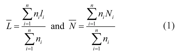

Figure 5 TEM images of six sulfided catalysts
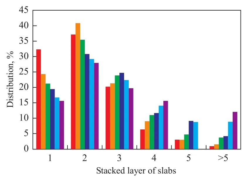
Figure 6 The detail distribution of stacked layer of slab for six sulfidized catalysts
whereliis the length ofith slab,niis the number of particles with alilength or Nilayers, andNiis the number of the layeri.Table 3 shows that the average number of stacked slabs increased from 2.136 to 3.22 with an increasing metal loading; this finding was attributed to decreasing metal-support interactions, which was consistent with the TPR results shown in Figure 3. The average slab length only increased from 3.06 nm to 3.36 nm because the same polymolybdate species could be found in all catalyst samples. The XPS spectrograms also confirmed these observations. Figure 6 shows the detailed distribution of the MoS2stacked slab layers of six sulfidized catalysts. Slab stacking of the monolayer decreased with an increasing amount of metal loading, indicating that fewer type I Ni-Mo-S structures were formed. The formation of the type II Ni-Mo-S structures increased with an increasing number of stacked layers (3—5). In the catalyst CMo25Ni, a larger number of stacked multilayers (>5) had inhibited sulfur atoms from approaching the active sites.
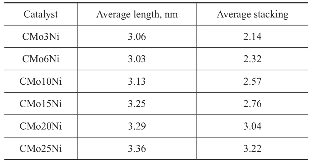
Table 3 The average slab length and stacking of six sulfidized catalyst
3.3 Catalytic activity evaluation
Figure 7 shows the results of HDS experiments performed in a fixed-bed microreactor. The catalytic activity of all samples increased with an increasing amount of metal loading. The HDS conversion rates on the catalysts CMo-20Ni and CMo25Ni were nearly identical (97%). Increase in HDS conversion may be explained by the increasing number of active sites and formation of the type II Ni-Mo-S structure. Thus, the performance of the catalysts is closely related with the microstructure of their active phase. The metal dispersed on the support forms a monolayer and the metal-support interaction is stronger at low metal loadings. After sulfidation, the sulfidation degree is lower and the number of single-layer stacked MoS2slabs is more than that in those catalysts provided with high metal loading. The type I Ni-Mo-S structures with low activity are dominant. The higher sulfidation degree and less single-layer stacked MoS2slabs after sulfidation treatment detected at higher metal loadings are attributed to weak metal-support interactions, which can form more type II Ni-Mo-S structures with high catalytic activity. Although higher metal loadings and sulfidation degree could form more active sites, more stacked slab layers and lower specific surface areas and pore volumes would inhibit sulfur atoms from approaching active sites.
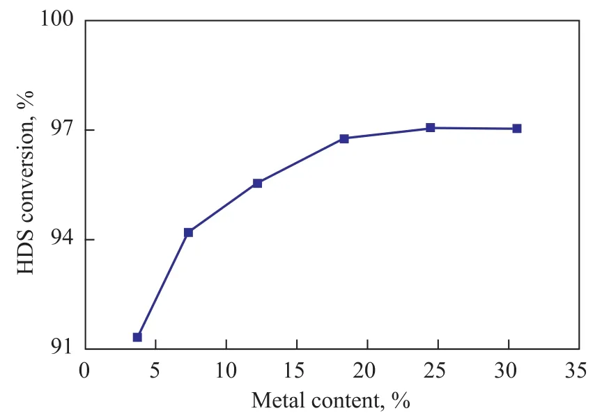
Figure 7 HDS conversion of six Ni-Mo catalysts with different metal loading
4 Conclusions
Using several characterization techniques and HDS activity tests, the active phase microstructures and the HDS activity of six catalysts with different amounts of loaded metals were analyzed. Under the experimental conditions specified in this work, only polymolybdate species were observed in all the oxidized catalysts. The sulfidation degree of Mo and the MoS2slab length did not change significantly after sulfidation. Increase in the NiSxsulfidation phase and MoS2slab stacking with an increasing amount of loaded metal was attributed to weak metal-support interactions. Increasing the metal loading could increase the number of active sites in the catalysts. The HDS activity of the catalysts increased initially with the number of active sites but remained relatively constant thereafter. This result was attributed to more stacked layers of slabs, and lower specific surface area and pore volume with excessive amount of metal loaded. This work confirms that HDS activity can be determined by the microstructure ofactive phase in the catalysts.
Acknowledgements:The authors thank SINOPEC for its financial support (No. 108012/ No. 108041), as well as Ye Liu from the Colorado School of Mines for facilitating helpful discussions and revising the writing in this article.
[1] Plantenga F L, Leliveld R G. Sulfur in fuels: more stringent sulfur specifications for fuels are driving innovation[J]. Appl Catal A: Gen, 2003, 248(1): 1-7
[2] Ultra Low-sulfur Diesel Regulations Take Effect in US[J]. Green Car Congress: Ultra Low-sulfur Diesel Regulations, 2006
[3] European Union. Fuel Regulations, Fuels[S]. http://www. dieselnet.com/standards/eu/fuel.php
[4] Japan: Diesel Fuel, Fuel Regulations[S]. http://www.dieselnet.com/standards/jp/fuel.php
[5] Perot G. Hydrotreating catalysts containing zeolites and related materials—mechanistic aspects related to deep desulfurization[J]. Catal Today, 2003, 86(1/4): 111-128
[6] Ho T C. Deep HDS of diesel fuel: chemistry and catalysis[J]. Catal Today, 2004, 98(1): 3-18
[7] Stanislaus A, MarafiA, Rana M S. Recent advances in the science and technology of ultra low sulfur diesel (ULSD) production[J]. Catal Today, 2010, 153(1/2): 1-68
[8] Song C. An overview of new approaches to deep desulfurization for ultra-clean gasoline, diesel fuel and jet fuel[J]. Catal Today, 2003, 86(1/4): 211-263
[9] Knudsen K G, Cooper B H, Topsoe H. Catalyst and process technologies for ultra low sulfur diesel[J]. Appl Catal A, 1999, 189(2): 205-215
[10] Daage M, Chianelli R R. Structure-function relations in molybdenum sulfide catalysts: The “rim-edge” model[J]. J Catal, 1994, 149(2): 414-427
[11] Topsoe H, Clausen B S, Massoth F E. Hydrotreating Catalysts[M]// Anderson J R, Boudart M. Catalysis: Science and Technology, vol. 11, Berlin: Springer Verlag, 1996: 31-33
[12] Helveg S, Lauritsen J V, Lægsgaard E, et al. Atomic-scale structure of single-layer MoS2nanoclusters[J]. Phys Rev Lett, 2000, 84(5): 951-954
[13] Topsoe H. The role of Co-Mo-S type structures in hydrotreating catalysts[J]. Appl Catal A: Gen, 2007, 322(16): 3-8
[14] Hinnemann B, Norskov J K, Topsoe H. A density functional study of the chemical differences between type I and type II MoS2-based structures in hydrotreating catalysts[J]. J Phys Chem B, 2005, 109(6): 2245-2253
[15] Saih Y, Nagata M, Funamoto T, et al. Ultra deep hydrodesulfurization of dibenzothiophene derivatives over NiMo/TiO2-Al2O3catalysts[J]. Appl Catal A: Gen, 2005, 295(1): 11-22
[16] Bejenaru N, Lancelot C, Blanchard P, et al. Synthesis, characterization, and catalytic performances of novel CoMo hydrodesulfurization catalysts supported on mesoporous aluminas[J]. Chem Matter, 2009, 21(3): 522-533
[17] Okamoto Y, Hioka K, Arakawa K, et al. Effect of sulfidation atmosphere on the hydrodesulfurization activity of SiO2-supported Co-Mo sulfide catalysts: Local structure and intrinsic activity of the active sites[J]. J Catal, 2009, 268(1): 49-59
[18] Parola V L, Dragoi B, Ungureanu A, et al. New HDS catalysts based on thiol functionalized mesoporous silica supports[J]. Appl Catal A: Gen, 2010, 386(1/2): 43-50
[19] Saih Y, Segawa K. Catalytic activity of CoMo catalysts supported on boron-modified alumina for the hydrodesulphurization of dibenzothiophene and 4,6-dimethyldibenzothiophene[J]. Appl Catal A: Gen, 2009, 353(2): 258-365
[20] Li H, Li M, Chu Y, et al. Essential role of citric acid in preparation of efficient NiW/Al2O3HDS catalysts[J]. Appl Catal A: Gen, 2011, 403(1/2): 75-82
[21] Guichard B, Ror-Auberger M, Devers E, et al. Aging of Co(Ni)MoP/Al2O3catalysts in working state[J]. Catal Today, 2008, 130(1): 97-108
[22] Blanchard P, Lamonier C, Griboval A, et al. New insight in the preparation of alumina supported hydrotreatment oxidic precursors: A molecular approach[J]. Appl Catal A: Gen, 2007, 322: 33-45
[23] Guevara-Lara A, Bacaud R, Vrinat M. Highly active NiMo/TiO2-Al2O3catalysts: Influence of the preparation and the activation conditions on the catalytic activity[J]. Appl Catal A: Gen, 2007, 328(2): 99-108
[24] Ozkan U, Schrader G L. NiMoO4selective oxidation catalysts containing excess MoO3for the conversion of C4hydrocarbons to maleic anhydride: I. Preparation and characterization[J]. J Catal, 1985, 95(1): 120-136
[25] Dufresne P, Payen E, Grimblot J, Bonnelle J P. Study of nickel-molybdenum-gamma-aluminum oxide catalysts by X-ray photoelectron and Raman spectroscopy. Comparison with cobalt-molybdenum-gamma-aluminum oxide catalysts[J]. J Phys Chem, 1981, 85(16): 2344-2351
[26] Rodriguez-Castellon E, Jimenez-Lopez A, Eliche-Quesada D. Nickel and cobalt promoted tungsten and molybdenum sulfide mesoporous catalysts for hydrodesulfurization[J]. Fuel, 2008, 87(7): 1195-1206
[27] Brito J L, Laine J. Reducibility of Ni-Mo/Al2O3Catalysts: A TPR Study[J]. J Catal, 1993, 139(2): 540-550
[28] Merida-Robles J, Rodrıguez-Castellon E, Jimenez-Lopez A. Characterization of Ni, Mo and Ni-Mo catalysts supported on alumina-pillared alpha-zirconium phosphate and reactivity for the thiophene HDS reaction[J]. J Mol Catal A: Chem, 1999, 145(1/2): 169-181
[29] Park Y C, Oh E S, Rhee H K. Characterization and catalytic activity of WNiMo/Al2O3catalysts for hydrodenitrogenation of pyridine[J]. Ind Eng Chem Res, 1997, 36(12): 5083-5089
[30] Ninh T K T, Massin L, Laurenti D, et al. A new approach in the evaluation of the support effect for NiMo hydrodesulfurization catalysts[J]. Appl Catal A: Gen, 2011, 407(1/2): 29-39
[31] Gao Q, Ofosu T N K, Ma S G, et al. Catalyst development for ultra-deep hydrodesulfurization (HDS) of dibenzothiophenes. I: Effects of Ni promotion in molybdenum-based catalysts[J]. Catal Today, 2011, 164(1): 538-543
[32] Alstrup I, Chorkendorff I, Candia R, et al. A combined X-Ray photoelectron and Mössbauer emission spectroscopy study of the state of cobalt in sulfided, supported, and unsupported CoMo catalysts[J]. J Catal, 1982, 77(2): 397-409
[33] Okamoto Y, Nakano H, Shimokawa T. Stabilization effect of Co for Mo phase in Co-Mo/Al2O3hydrodesulfurization catalysts studied with X-Ray photoelectron spectroscopy[J]. J Catal, 1977, 50(3): 447-454
[34] Cho A, Koh J H, Lee S I, et al. Activity and thermal stability of sonochemically synthesized MoS2and Ni-promoted MoS2catalysts[J]. Catal Today, 2010, 149(1/2): 47-51
[35] Portela L, Grange P, Delmon B. XPS and NO adsorption studies on alumina-supported Co-Mo catalysts sulfided by different procedures[J]. J Catal, 1995, 156(2): 243-254
[36] Eijsbouts S, van den Oetelaar L C A, van Puijenbroek R R. MoS2morphology and promoter segregation in commercial Type 2 Ni-Mo/Al2O3and Co-Mo/Al2O3hydroprocessing catalysts[J]. J Catal, 2005, 229(2): 352-364
Recieved date: 2014-03-31; Accepted date: 2014-05-15.
Prof. Shen Benxian, Telephone: +86-21-64252851; E-mail: sbx@ecust.edu.cn.

- 中国炼油与石油化工的其它文章
- Experimental Study on Liquid-Liquid Equilibria of Alcohol- Ester-Water-CaCl2System
- Synthesis of PE with Broad MWD Catalyzed by Supported Ziegler-Natta Catalyst Consisting of Cycloalkoxy Silane as IED
- Friction Characteristics of Space Lubricating Oil No. 4129 in Rolling and Sliding Contact
- Research on New Silica Sol Matrix Used in Fluid Catalytic Cracking Reaction
- Corresponding Factors Influencing Crude Oils Assay Using Low-field Nuclear Magnetic Resonance
- Research on Hydrolysis and Saccharification of Corn Stover