Bond strength analysis of the bone cement- stem interface of hip arthroplasties
Lan-Feng Zhang, Shi-Rong Ge, Hong-Tao Liu, Kai-Jin Guo, Shu-Yang Han, Juan-Yan Qi
1Institute of Tribology and Reliability Engineering, School of Mechanical and Electrical Engineering, China University of Mining and Technology, Xuzhou 221116, China
2Department of Surgery, the Second Xu-zhou Hospital, Xuzhou Medical University, Xuzhou, Jiangsu 221000, China
Bond strength analysis of the bone cement- stem interface of hip arthroplasties
Lan-Feng Zhang1*, Shi-Rong Ge1, Hong-Tao Liu1, Kai-Jin Guo2, Shu-Yang Han1, Juan-Yan Qi1
1Institute of Tribology and Reliability Engineering, School of Mechanical and Electrical Engineering, China University of Mining and Technology, Xuzhou 221116, China
2Department of Surgery, the Second Xu-zhou Hospital, Xuzhou Medical University, Xuzhou, Jiangsu 221000, China
Objective: To study and establish the preliminary linear and modified models for the interface shear mechanics performance between implant and bone cement and to explore its damage significance. Method: The loosening research between artificial hip joint prosthesis stem and bone cement interface performance can be evaluated by the push-in test. Based on the debonding performance test, the analytical expressions of the average load and displacement from the debonding failure and splitting failure process were deduced and determined. The correlations of the expressions of the average load-displacement and statistical experimental data were analyzed. Results: It demonstrated that the interface debonding failure mechanical model could be characterized as interface bond strength mechanical performance. Based on analysis of models and experimental data by the three statistical analysis methods, the results indicated the modified model could be better represented by the interfacial debonding strength properties. The bond stressτand relative sliding s distribution along the embedment regional were coupling affected by both pressure arch effect and shear lag effect in bone cement. Two stress peaks of implant have been found at the distance from 0.175Laloading tip to 0.325Lafree tip, which also verified the early loosening clinical reports for the proximal and latter region. As the bone cement arch effect, the bond stress peak tend to move to the free tip when the debonding failure would be changed into the splitting failure, which presents a preliminary study on the mechanism of early debonding failure for the stem-cement interface. Conclusions: Functional models of the stembone cement interfacial debonding failure are developed to analyze the relevant mechanism. The different locational titanium alloy stress, and the interfacial bond stress and the relative slides are evaluated to acquire a guide of the different positions of interfacial damage. The coupling effect which is original from the pressure arch and the interfacial shear hysteresis cumulative effect has influence on the interfacial debonding and damage process.
ARTICLE INFO
Article history:
Received 10 September 2013
Received in revised form 15 October 2013
Accepted 15 December 2013
Available online 20 Februany 2014
Bone cement mantle
1. Introduction
Aseptic loosening of the femoral component has been identified as the major failure mechanism of cemented total hip arthroplasties (THA), which is often accompanied by cement fractures and disruption of the stem-cement interface[1]. Statistical results[2-5] revealed that stems had higher revision rates due to aseptic loosening beyond 5 years and for aseptic loosening rate is 87% for 20 years. Numerous studies[6-10] concluded reasons for cemented hip implants loosening were resulted from the micro-cracking formation initiated at the stem-cement interface towards the cortical bone. Whereas they analyses the bone cement-stem interface loosening by nonlinear method and simulated the demanding character through computer and experiments. Results (debonding and elastic micro-slid) were influenced by the bone cement-stem interface stress. Analyses of debonding and micro-slid characters have showed that fatigue stress uneven distribution induced cement damageand the interface loosening. Even the interfacial creep and fatigue damage which would induce stem continue to be sinking in cavity. Kroell[11] implied stems failed after early and late onset migration alike, while late migration was the predominant pattern in cemented stems. Harris[12] proposed these fractures which are frequently associated with a loose femoral component. Ramos[13] demonstrated more damage (cracks per area) which are mainly on the proximal part of the cement mantle. The micro-cracking formation initiated in the stem-cement interface and grew towards the direction of cortical bone of the femur which induced the early period stem-cement interfacial debonding. Pérez[14] has established the stem-cement interface failure model by means of the cohesive surface theory that was implemented into a specific interface element. The damage accumulation and creep in bone cement were formulated through the non-linear theory of continuum damage mechanics, which could be simulated the progressive debonding of the stem-cement interface on the prediction of long-term implant loosening, which demonstrated that the stem-cement interface micro-motion fatigue behavior induced interfacial stress fracture and damage generation and crack propagation, even result in the interfacial loosening. Zhang[15-18] studied the influential factors of the stem-cement interfacial debonding on failure, but they are not clear yet, so it is necessary to establish the interfacial mechanical models to analyze prosthesis with stem and bone cement interfacial debonding and damage. Medical cases[1-4] showed that debonding at the interface is an important factor for the initiation of cracks, and some results obtained in vitro some experiments, but it had not been conducted for the primary reason of the interface debonding during the primary period.
Many researches were contributed to the fatigue damage for the interfacial debonding while few studies have analyzed the early survival of cemented primary THA, and the prostheses stem have been studied for their endurance without the adequate knowledge of initial debonding mechanic. Nevertheless the early cracks formation is original from the early rehabilitative training of patients. The interfacial micro-cracks have been formatted in the rehabilitative training of the body’s weight and loads period. Consequently, the effect of the initial debonding damage has not sufficiently been taken into consideration. This present study therefore aims to gain a better understanding on the static loading debonding mechanism at the stem-bone cement interface.
2. Materials and Methods
2.1. Materials
Diameter Φ10mm Ti6AL4V rods which surface roughness is 1.5μm; Acrylic Bone Cement III type (Tianjin Synthetic Material Research Institute); Strain Gauges (BQ120-3BB) ; Data Acquisition Instrument; Universal Testing Machine of Electronic Materials; Ultrahigh P 3d Morphology Morphology; PVA TePLa Ultrasonic Microscope; PHOENIX NANOMEX1X X-Ray detector2.2 Samples
2.2. Samples
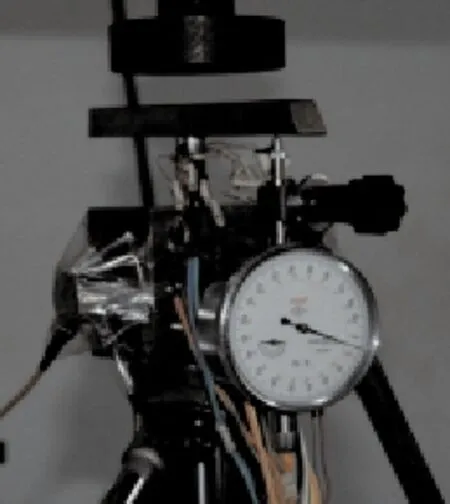
Figure 1. Bond strength properties test of the stem-bone cement interface.
Two grooves (Deep 1.2 mm×width33.5 mm) have been machinated by both sides of Φ10 mm Ti6Al4V rods. In order to be adhered to strain gauges, surficial roughness of the buffing groove should be made in 2 μm and the embedment depth of bone cement is 40 mm. They were divided into four regions and each of them has a distance of 10 mm. Two strains gauge were fixed at each position and there were eight strains gauges in all. Figure 1 shows that each strain gauge would be connected by a copper conductor which is external data collector equipment. After the strain gauges have been posted, Glue 702 should be watered on the grooves to prevent the strain gauges from being wet and being destroyed in the experiment. To prevent the occurrence of adverse effects of interfacial bond, the watered glue 702 should be dried after 48 hours and the titanium rods should be realized with escaping sludge and oil. First and foremost, the titanium alloy rod should be inserted at the center axis position. Moreover, mixture integration of the surgery bone cement should be poured into the mold and solidified the bone cement for 24 hours after the process. The last is to make sure the restraining force on the mold and specimen after closed the cover. Bone cement was prepared in accordance with ISO5833 standard.
2.3. Experiment principle
The interfacial bond stressτcan be derived by the local stressσswhich the governing equation becomesσS=ES•εS. The rod stress has a small error which may cause interfacial bond change greatly because of a largemagnetite difference between the rod stress and interfacial bond stress, which may lead to be measured distortion. So it is important to discuss the interfacial bonding properties of rods and bone cement. Based on the theoretical analysis and he measured data, to analyze the structure of rod stress, meanwhile accuracy and consistency for theoretical results should be checked. The model of theory analysis in accordance with shear lag effect is presented as the specimen under the extrusion load. The interfacial bond stress of rod and bone cement verse interface slip relationship is shown as Figure 2, whose curve was divided into the debonding segment 0<S<Spfand splitting failure segmentSpf<S<Ssr. The experiment should be stopped when the interfacial bond stress-slip relationship enters into a failure segment.
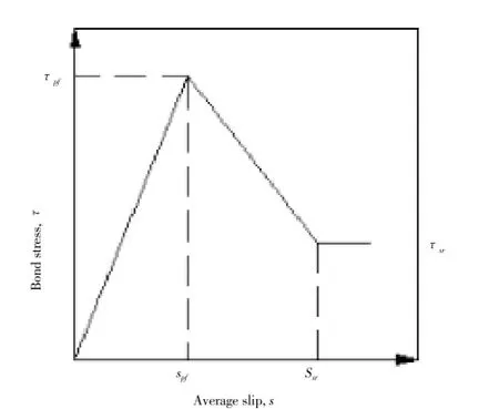
Figure 2. Interfacial debonding analytical model curve.
2.4. Theory methods
Figure 3 shows that the length of ”dx” rod-bone cement micro-unit force balance analysis. Stress acts on the microunit length “dx” unit. The force equilibrium equation including two values can be defined asAc•σc+As•σs=0. By means of formula derivation the bond stress versus slip relationship aboutxdifferential equation can be given as.d2S(x)/dx2-τ•4(1+αμ)/d•Es=0.

Figure 3. Load acting on bone cement- rod element of length dx.
2.4.1. A linear model theory methods
A mathematical model which predicted two segments of the interfacial debonding failure is proposed for predicating the relationship between bond stress and slip, which can be written asτ=Eb•S(0≤S≤Spf).
2.4.2. A modified model theory methods
In order to improve analysis and predict the interfacial bond stress versus slip response fundamental material characteristic, a new power index modified model has been attempted to analyze the relationship of the interfacial bond stress versus slipτ=τ(s). The interfacial debonding process can be approximately expressed by an exponential function. The amount of slip has been increased as quickly as the interfacial between titanium alloy rod and bone cement in the debonding failure segment as a result of the sliding friction force against the interfacial dislocation between different materials, which the curve can be described by exponential.
2.5. Statistical analysis
Statistical analysis was performed by Statistical Package for Social Sciences 16.0 software (SPSS Inc., Chicago, IL, United States). In statistical analysis Pearson correlation coefficient test, residual analysis test, euclidean distance and Chebychev statistical distance test were used for models and experimental data evaluation. Statistical significance was assigned to P<0.05.
3. Result
3.1. Linear model and expression for interfacial failure
3.1.1. Prediction of bond stress and slip of specimens to debonding failing
A mathematical model which is used to predict the response of specimen failing by push-in test is shown in Figure 2. A linear relationship between bond stress and slip has been assumed.
The average slip,Savat the top and bottom of the specimen is used to predict the response of the standard push-in test. In order to improve the predictability and increase the practicability of the theoretical model, the experimental data have been fitted by a piecewise-linear curve. The debonding segment is 0<S<Spf, when the interface produces the maximal slip.τpfis the maximum bond stress corresponding toSpf. It has been accepted that the slop=4 472.86 and intercept= -66.16 of the fitted curve (Figure 4a). So theτ-sexpression of debonding failure segment can be given asτ=4 472.86S-66.16. By means of formula derivation, thePtand the average slip,Sav, can be expressed as:

3.1.2. Prediction of bond stress and slip of specimens to splitting segment failure
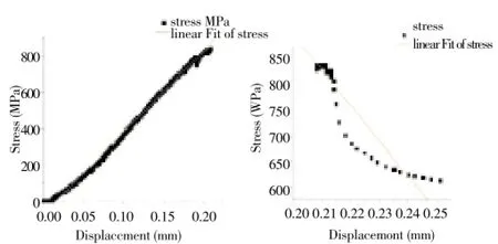
Figure 4. (a) Linear fitted curve of debonding failure; (b) Linear fitted curve of splitting failure.
A model is used to predict the response of a specimen failing by splitting. The average slip,Sav, which can be calculated for the top and bottom of the specimen in the standard shear test is used to predict the response of the standard push-in test. For the splitting failure segmentSpf<S<Ssr, the slop=-10 901.26 and intercept= 3 128.53 of the fitted curve have been accepted (Figure 4b). So theτ-sexpression of splitting failure segment can be written asτ=-10 901.26S+3 128.53. By means of formula derivation, the relationship between the push force,Pt, and the average slip,Sav, can be expressed as follows:

3.2. Modified model for interfacial failure
3.2.1. Modified failure model for debonding segment and analytical expression
The debonding failure relationship of bond stress-slip can be defined asτ=B•Sa. The average slip,Sav, which can be calculated for the top and bottom of the specimen in the standard shear test, is used to predict the response of the standard push-in test. Based on the experimental data, the relationship between the push force,Pt, and average slip,Savcan be expressed as follows:

3.2.2. Modified failure model for splitting segment and analytical expression
The interface between titanium alloy and bone cement have been deboned during the splitting failure segmentSsf<S<Ssr, which means wrapping hoop mechanics of interface between titanium alloy and bone cement have failed. The interfacial slip shows the solar laniary tendency. The wrapping hoop force and push-in force are composed of a sliding friction mechanism. The friction coefficient of sliding interface is real. In order to characterize the interface slip, analytical expressions for predicting the relationship of bond stress versus slip response is described byτ=B•Sa, meanwhile the slope of splitting failure segment curve. By means of formula derivation and based on the experimental data, the relationship between the push force,Pt, and average slip, Sa, can be expressed as follows:

Figure 5 (a) and (b) show the modified model fitted of bond stress versus slip responses obtained from tests simulating a uniform bond stress distribution of specimens failing in debonding and splitting segment. The existence of the interfacial sliding friction is the fact that the splitting failure segment can be simplified as a linear by the modified model.
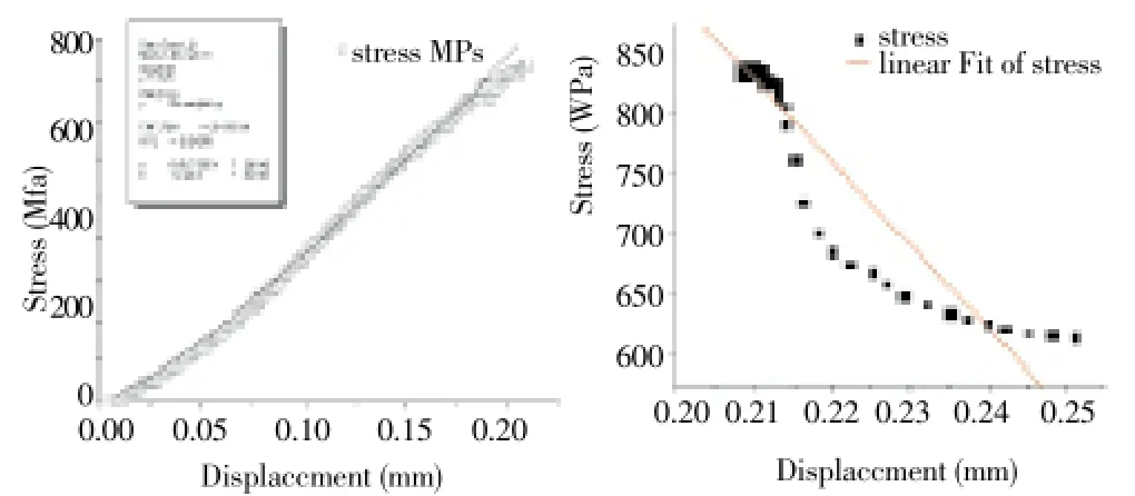
Figure 5. a) Modified model fitted of the interface debonding segment; b) Modified model of fitted for interface splitting failure.
3.3. Statistical analysis
As the Table 1 shows, all of the Pearson correlation coefficient was 0.999, which demonstrated the value from three models was more appropriate for the experimental stress data. Based on the Euler distance statistical analysis and Chebyshev distance statistic analysis, the unsimilar statistical analysis of modified stress model is 3 433.035 in the debonding experiment and 3.455×10¹⁹in the linear fit stress model and even the 7.723×10¹⁵in the theoretical stress model, which suggested the modified model is mostly appropriate for analysis the data (Table 2). Satistical result showed the coefficient of determination (Adj. R-Squre), the goodness of the fit parameters was closer to 1 (Table 3). The determinate coefficient of the modified model was very close to 1 in three models. Compared with the coefficient of ReducedChi-Sqr, the value of modified model was the nearest to zero which was fit with the experimental data for best. The residual fitted results showed that the residual sum of squares of modified model among the three models was minimal. Through the analysis of these points displayed random distribution shape in the residual plots, 62% of the theoretical model points has fallen into±2δwhile 78% into ±δ. Meanwhile the linear fitted degree was 68.5% of the points fall into±δand even 84% into±2δ. Fatherless 73% points of modified model falls into±δ, while 96% of the points fall into±2δ. The result demonstrated that the modified model was fitted better than other models. All inall, the statistical results indicate the modified model can better stand for the interfacial debonding performance. Based on the splitting failure segment of debonding curve, the bone cement and titanium alloy interfacial debonding and cracks phenomenon have existent. The splitting failure segment does not belong to the debonding mechanism without statistical analysis.

Table 1 Similar statically analysis of different models

Table 2 Unbiased estimatation analysis.
3.4. Local bond-slippage distribution characteristics
3.4.1. Different positions stress (σ-x) of implanted stem
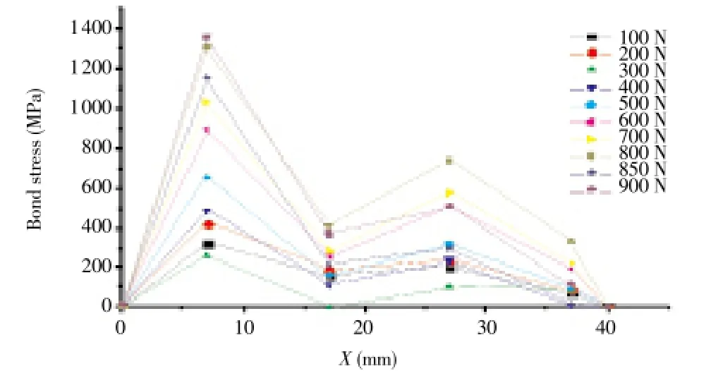
Figure 6. Titanium alloy rod stress-location σ-x relationship of different interface positions.
During the loading increasing procession (Figure 6), the loading tip stress was not large while two peaks stress of titanium alloy rod have been found at the 0.175Laposition distance from loading tip and 0.325Laposition distance from free tip, which was resulted from force constrain increasing of the loading tip, meanwhile the bond stress of the interface was on the increase so that the titanium alloy shank stress concentration in the proximal position. As the end of the bone cement- rod interface was subject to the vertical pressure, the stress peak which appears at the distance 0.325Laposition from free tip could resist the interfacial sliding friction of free tip.
3.4.2. Slips relationship(s-x) of different relative position interface of the bone cement-stem
As the bond stress lags behind effect, the slippage of free tip is lower than the loading tip’s. The slippage of the free tip is as little as not obviously before the interfacial debonding failure. Therefore the slippage of the different local position presented a decreasing tendency from loading tip to free tip during the debonding process (Figure 7). As the bond strength accumulation process from the loading to the free tip, the slope of the slip curve was decreasing from the loading to free tip. The whole interfacial slippage was very little during the debonding early time. Microcracks should be produced in the implanted components at once when the load was greater than the ultimate bond stress value. The bond strength would immediately begin to decline, so that the slop of the trend of the slippage curve was increasing. When the interfacial completely debonded, the slippage of free tip was gradually as same as the loading tip. This segment tendency demonstrates that the interface is gradually in debonding process. While the interfacial relationship between bond stress and slip is linear in the splitting failure.
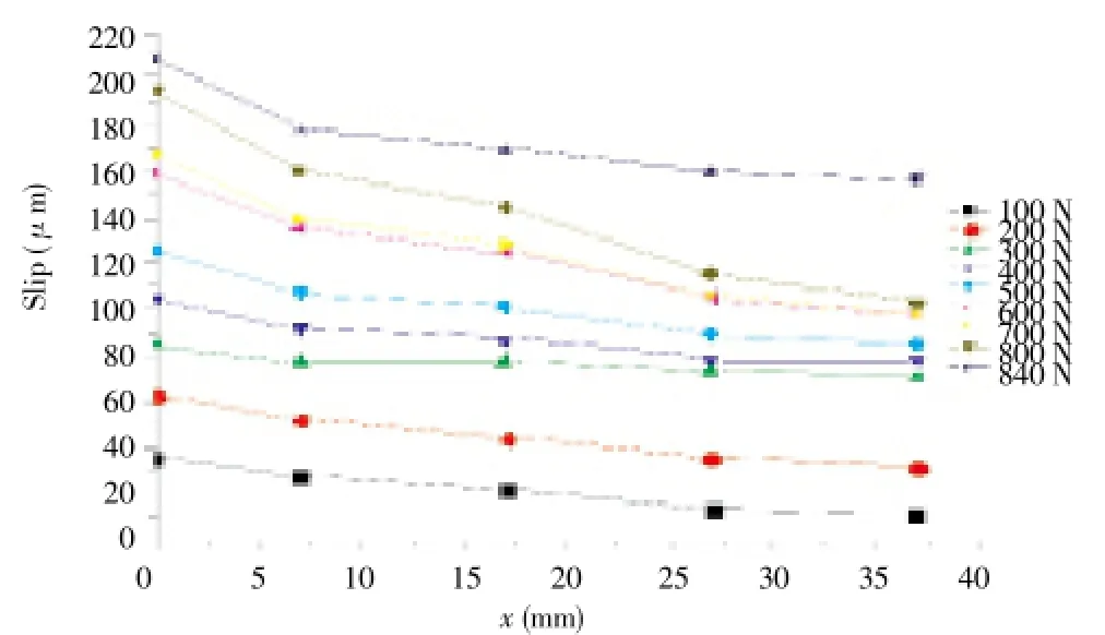
Figure 7. Slip-location s-x relationship of different interface positions.

Table 3 Unsimilar statistical analysis of different models
3.4.3 Bond stress relationship (τ-x) of different relative position interface of the bone cement-stem
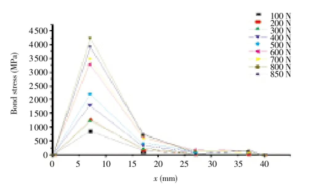
Figure 8. Bond stress-locationτ-x relationship of different interface positions.
The bond stress is unevenly distributed at different positions (Figure 8). Compared with different position bond stiffness, theτ-x curve should be composed. This curve demonstrates that bond stress changed ratio of different anchoring depth (τ-x), where bond anchor stiffness along the anchoring length variation. It has been showed that two bond stress peaks have been found at the 0.175Ladistance of loading tip and 0.075Laof the free tip of the samples, respectively. Moreover the bond strength peak of the 0.175Ladistance of loading tip is higher than the others, while the stiffness of loading and free tips were lower whose tendency is declined. The bond stress peak which is near the free tip has been affected by the bearing vertical pressure, causes the interfacial sliding friction of titanium alloy rod and bone cement. Once the protective layer of bone cement has initiated cracks, the bond stress peak would be disappearing as soon as possible. This phenomenon demonstrated that the vertical pressure effect is resulted from the interfacial bond anchoring effect of titanium alloy rods and bone cement, which is gradually reduced and even eliminated.
3.4.4. Bond stress-slip relationship (τ-s) of different relative interfacial position
The different position curve of bond stress-slip relationship is unlike (Figure 9). The variable value α of modified predicting model continues to become lower, while the average value wasaav=0.88. The reason was an interfacial bond lag effect has been produced on the interfacial anchorage embedment region. The longer of anchorage lengths, the more obvious interface shear lagged additive effect. The shear lag effect was induced by the lower bond stress at the first position which was lower than the other positions. As Figure 9 shows, the proximal position of titanium alloy rod was subject to the higher stress which induced a stress concentration phenomenon. The titanium alloy material owned a good ductility, so as to realize rods with a large deformation. The brittle material characteristic of bone cement has played a good reinforced role on rod. This position bond stress-slip fitted function was approximately linear. The interface shear lag additive had an effect on the slope of the bond stress-slip which was continuous decreasing. It indicates the value α is also decreased and the arch effect of bone cement pressure is verified.
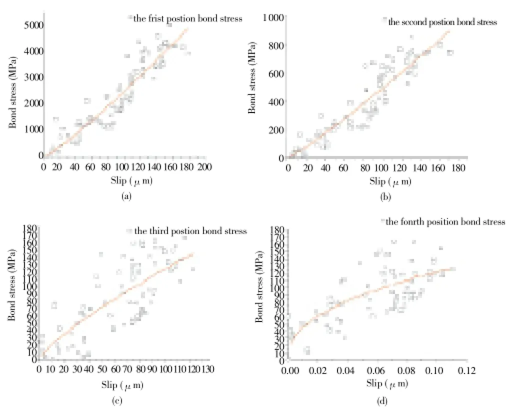
Figure 9. Bond and slip relationship of different positions: a) first position; b) second position; c) third position; d) four position.
4. Discussion
The linear model and modified exponential model for predicting the interfacial bond stress and slip relationship between bone cement have been found in this paper. The analytical expressions of the titanium alloy stressσs, and the interfacial bond stress and the relative slidesare established by theoretical analysis and formula deduction. Combined with the demanding experiments data, the predicted interfacial bond stress-slip relationship have been formula deducted. Meanwhile, analytical expressions of average load-displacement is also formula deducted. Based on the test data, the feasibility of these models and mathematical expressions have been verified by using the mathematical statistics analysis.
The bond stress-slip relationship could be changed into the anchoring samples along with different positions. Two titanium alloy stress peaks have been found at the distance from 0.175Laloading tip to 0.325Lafree tip, which also verified the clinical reports about stress concentration atthe stem proximal and lateral position. The interfacial shear lags effect makes the amount of free tip slippage lower than loading tip’s, because the tendency of the slippage amount along the anchoring length is decreasing. As the bone cement arching effect, the bond stress peak tends to move to the free tip which means the intensify compression of the components makes cement arching effect move toward free tip. Until the arch effect reaches the free tip, the debonding failure would be changed into the splitting failure. The pressure arch effect has an influence on the bond stress-slip relationship of different positions (τ-s), which verified the interfacial shear hysteresis cumulative effect. It is helpful to demonstrate that the interfacial stem-bone cement debonding mechanics.
The success of a total hip arthroplasties is directly related to the reliability and lifetime of its implants which could reconstruct patient’s health. It is significant) for the implant loosening damage that the effect of different designed stems. What we sought to the initial debonding mechanism is to promote the quality of implant stems reliability. On one hand, the optimal size cement stems could reduce the early interfacial debonding and loosening. On the other hand, the designed surface morphology of the stem makes great effect on the reliability of interfacial bond stress.
Conflict of interest statement
The authors declare that there is no conflict of interest
Acknowledgements
Individuals or units other than the authors who of direct help in the work could be acknowledged. This research is supported by the National Natural Science Foundation of China under Grant No. 51075387, and Science Foundation of the Ministry of Health of the People’s Republic of China under Grant NO.LW201004.
[1] Weinans H, Huiskes R, Grootenboer H. Trends of mechanical consequences and modeling of a fibrous membrane around femoral hip prostheses. J Biomechanics 1990; 23(10): 991-1000.
[2] Espehaug B, Furnes O, Engesaeter LB, Havelin LI. 18 years of results with cemented primary hip prostheses in the Norwegian Arthroplasty Register: concerns about some newer implants. Acta Orthop 2009; 80(4): 402-412.
[3] Clauss M, Luem M, Ochsner PE, Ilchmann T. Fixation and loosening of the cemented Müller straight stem a long-term clinical and radiological review. J Bone & Joint Surg, British Volume 2009; 91(9): 1158-1163.
[4] Wroblewski B, Siney P, Fleming P. Charnley low-frictional torque arthroplasty follow-up for 30 to 40 years. J Bone & Joint Surg British Volume 2009; 91(4): 447-450.
[5] Amstutz HC, Le Duff MJ. Cementing the metaphyseal stem in metal-on-metal resurfacing: when and why. Clin Orthop Relat Res 2009; 467(1): 79-83.
[6] Verdonschot N, Huiskes R. Mechanical failure in total hip arthroplasty with cement. Curr Orthop Jasty 1993; 7: 239-247.
[7] Verdonschot N, Huiskes R. Cement debonding process of total hip arthroplasty stems. Clinical Orthop Related Res1997: 336: 297-307.
[8] Verdonschot N, Huiskes R. Mechanical effects of stem cement interface characteristics in total hip replacement. Clinical Orthop Related Res 1996; 329: 326-336.
[9] Verdonschot N, Tanck E, R. Huiskes R. Effects of prosthesis surface roughness on the failure process of cemented hip implants after stem-cement debonding. J Biomed Materials Res 1998; 42(4): 554-559.
[10] Verdonschot N, Huiskes R. Subsidence of THA stems due to acrylic cement creep is extremely sensitive to interface friction. J Biomechanics 1996; 29(12): 1569-1575.
[11] Artur K, Paul B, Martin K, Hannes B, Bernd S, Rainer B. Aseptic stem loosening in primary THA: migration analysis of cemented and cementless fixation. Int Orthop 2009; 33(6): 1501-1505.
[12] Harris B, Owen JR, Wayne JS, Jiranek WA. Does femoral component loosening predispose to femoral fracture?: an in vitro comparison of cemented hips. Clin Orthop Relat Res 2010; 468(2): 497-503.
[13] Ramos A, Simões J, The influence of cement mantle thickness and stem geometry on fatigue damage in two different cemented hip femoral prostheses. J Biomechanics 2009; 42(15): 2602-2610.
[14] Pérez MA, Garcia-Aznar JM., Doblare M., Seral B, Seral F. A comparative FEA of the debonding process in different concepts of cemented hip implants. Med Eng Phys 2006; 28(6): 525-533.
[15] Zhang H, Brown L, Blunt L. Static shear strength between polished stem and seven commercial acrylic bone cements. J Materials Sci Materials Med 2008; 19(2): 591-599.
[16] Zhang H, Brown LT, Blunt LA, Barrans SM. Influence of femoral stem surface finish on the apparent static shear strength at the stem-cement interface. J Mech Behav Biomed Mater 2008; 1(1): 96-104.
[17] Zhang H, Brown L, Blunt L. A better understanding of the surface topography at the stem-cement interface. Proceed Asme/Stle International Joint Tribology Conference Pts A and B 2008; 513-515.
[18] Zhang H, Brown L, Barrans S, Blunt L, Jiang XQ. Investigation of relative micromotion at the stem-cement interface in total hip replacement. Proceed Institution Mechanical Engineers Part H: J Eng Med 2009; 223(8): 955-964.
*Corresponding author: Lan-Feng Zhang , Institute of Tribology and Reliability Engineering, School of Mechanical and Electrical Engineering, China University of Mining and Technology, Xuzhou 221116, China.
Tel: +86 051683754539.
E-mail: zhanglf@cumt.edu.cn.
Foundation project: This research is supported by the National Natural Science Foundation of China under Grant No. 51075387, and Science Foundation of the Ministry of Health of the People's Republic of China under Grant NO.LW201004.
Stem-cement debonding
Titanium
Total hip arthroplasty
 Asian Pacific Journal of Tropical Medicine2014年2期
- Asian Pacific Journal of Tropical Medicine的其它文章
- Diagnosis and multi-modality treatment of adult pulmonary plastoma: Analysis of 18 cases and review of literature
- Mathematical modeling for selecting center locations for medical and health supplies reserve in Hainan Province
- Comparison on serum biomarkers for anovulatory and ovulatory dysfunctional uterine bleeding in Lizu females
- Comparative analysis of different cyclosporine A doses on protection after myocardial ischemia/reperfusion injury in rat
- Hepatic effect of NAC on sevear acute pancteatise of rats
- Preparation of novel biodegradable pHEMA hydrogel for a tissue engineering scaffold by microwave-assisted polymerization
